Home Automation 8-Layer Stackable HAT for Raspberry Pi (v4.0)
Price:
Sale price
£73.80
Stock:
Login / Signup
Cart
Your cart is empty


The ideal solution for your Raspberry Pi home automation projects - expandable and stackable up to 8 layers with other cards from the Sequent range - and now with a custom Home Assistant integration!
Update for v4.0! the latest release has two new communication ports: 1-Wire and RS485.
Read temperatures in up to 8 zones with analog inputs. Control your heating and cooling system with the 8 onboard relays. Stackable design - add an additional 8-Relays board to control your sprinklers or a 4-Relays board to control high voltage appliances. Use the 8 optically isolated digital inputs for your security system. Activate the hardware watchdog to monitor and power cycle the Raspberry Pi in case of software lockup. Control four-light systems with the four PWM open-drain outputs (you supply external power up to 24V). Control four-light dimmers using 0-10V outputs.
Everything you need for Raspberry Pi home automation in a single, high-quality HAT.
For any technical questions about this product please email support@sequentmicrosystems.com
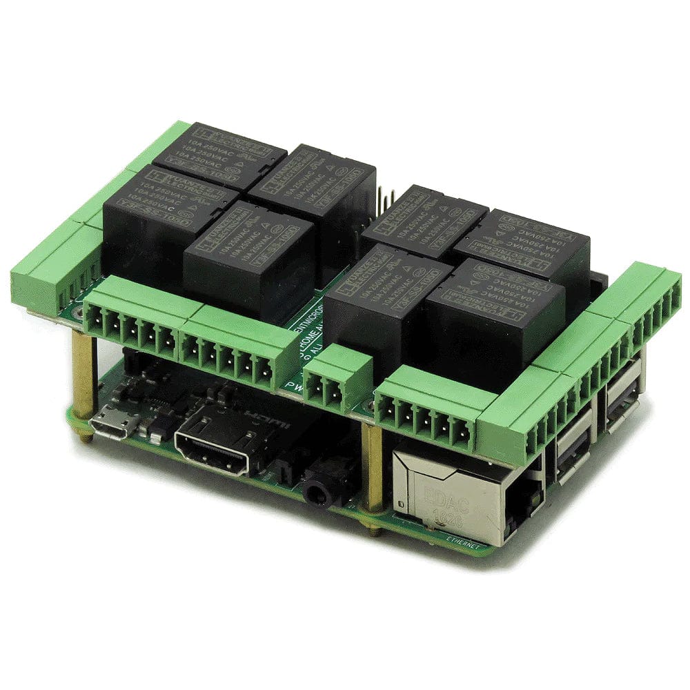
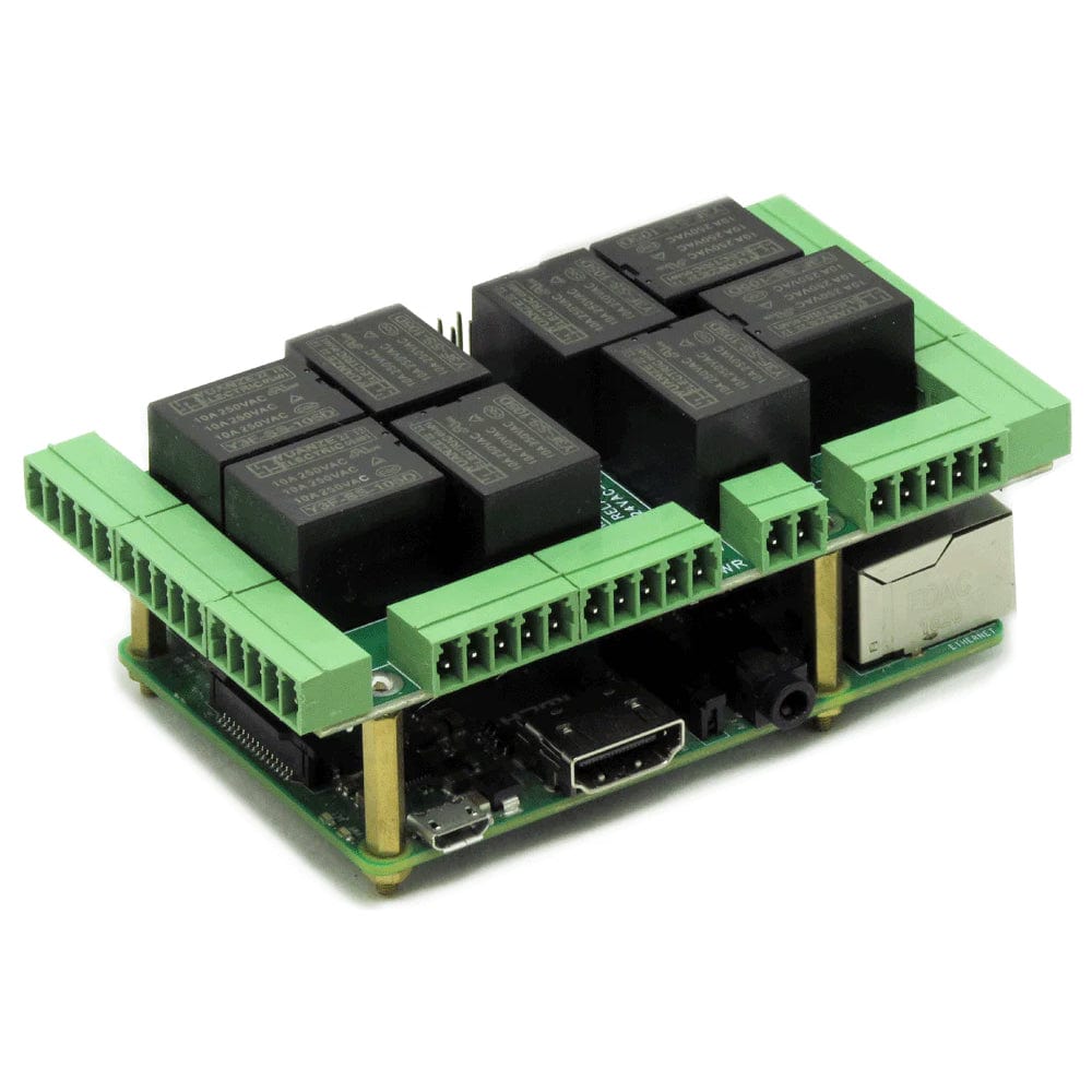
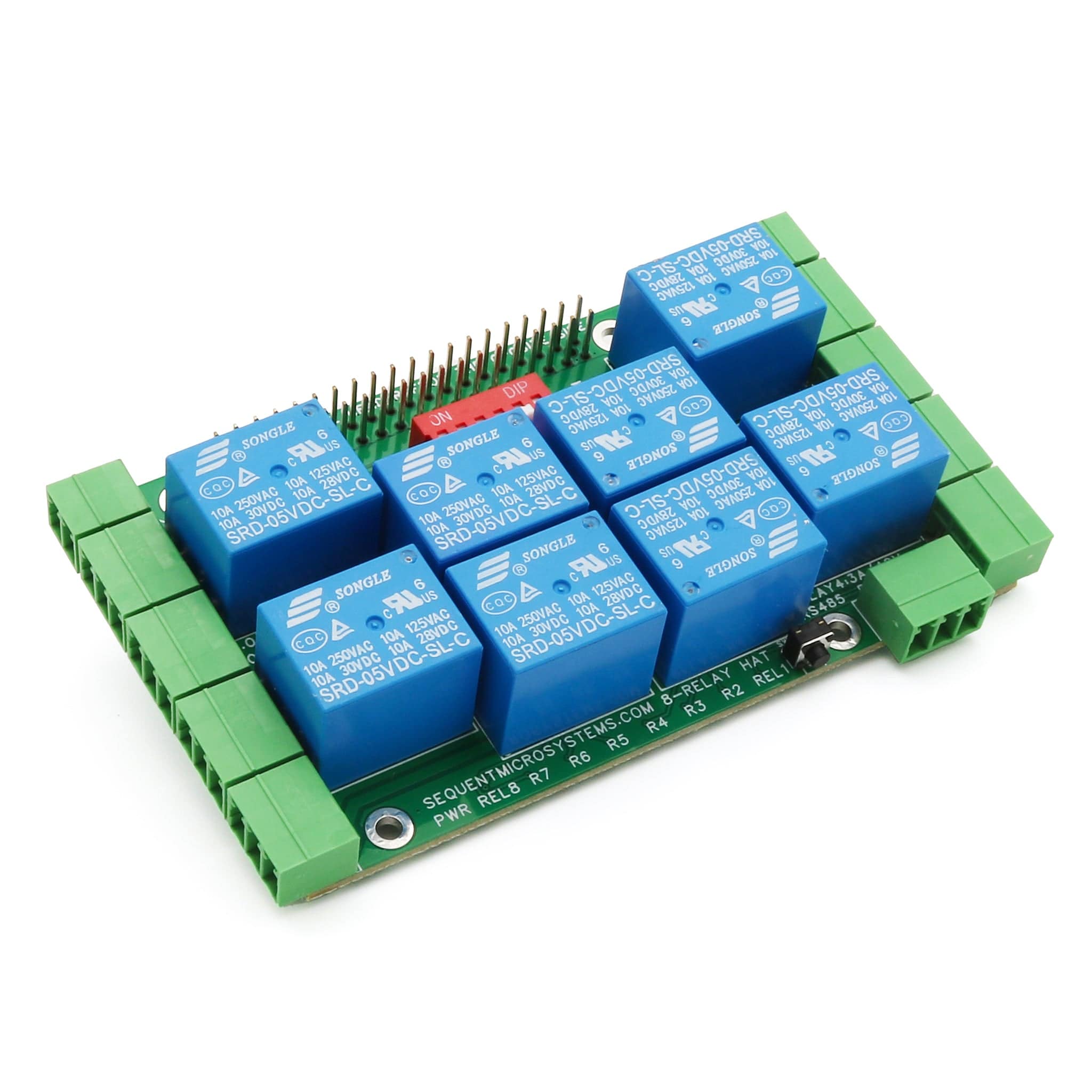
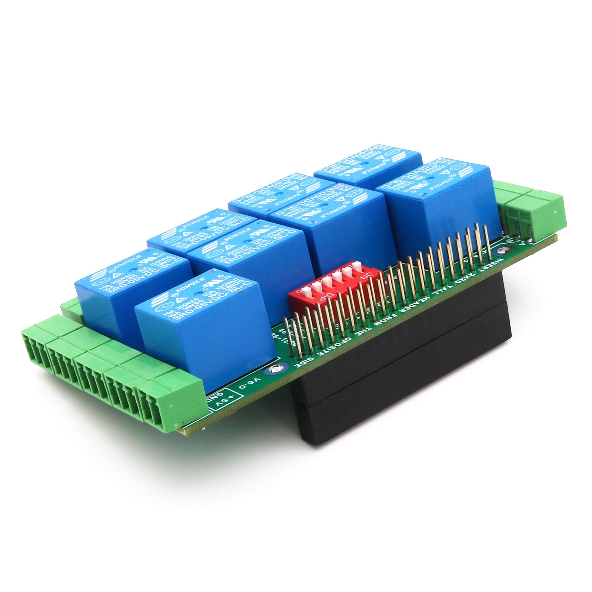
This latest version of the Home Automation HAT has been redesigned to use only pluggable connectors. Due to the large number of I/Os, the previous version used a 40 pin, right-angle header. By removing the N-C contacts of the relays (seldom used), Sequent made enough room on the periphery for pluggable connectors with just a minor increase in board dimensions.
Despite the crowded layout, they also added a DC-DC, 5V to 12V step-up power supply to power the 0-10V outputs. Now you can control four dimmers without the need for an external 12V power supply!
Sequent also added a general-purpose push-button wired directly to a Raspberry Pi GPIO pin. You can write a script that captures the pin state and use it to turn on a relay or an output, or to shut down the Pi when a keyboard and monitor is not available.
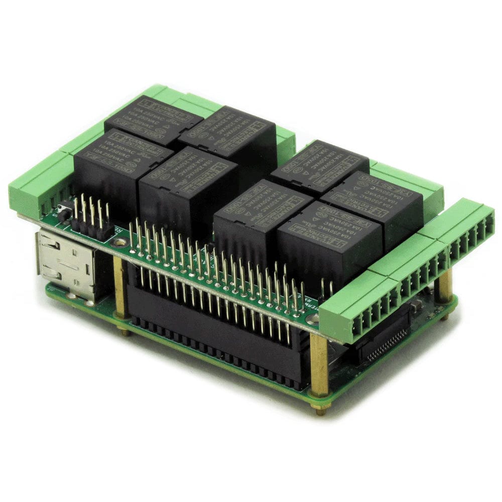
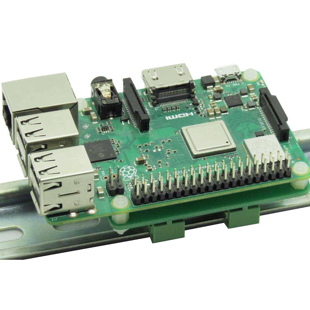
The card is compatible with all Raspberry Pi versions from Zero to 4. It shares the I2C bus using only two of the Raspberry Pi’s GPIO pins to manage all eight cards. This feature leaves the remaining 24 GPIOs available for the user.
The Home Automation card needs 5V to operate and can be powered from Raspberry Pi or from its own 2.1mm barrel connector. The tip is +5V and the ring is ground. The onboard relay coils are also powered from the 5V. A local 3.3V regulator powers the rest of the circuitry. The card needs 50mA to operate with all relays off. Each relay needs up to 80 mA to turn on.
The 8 onboard relays have contacts brought out to heavy-duty pluggable connectors, which make the card easy to use when multiple cards are stacked up. Relays are grouped in two sections of four relays each, with one common terminal and one N-O contact for each relay.
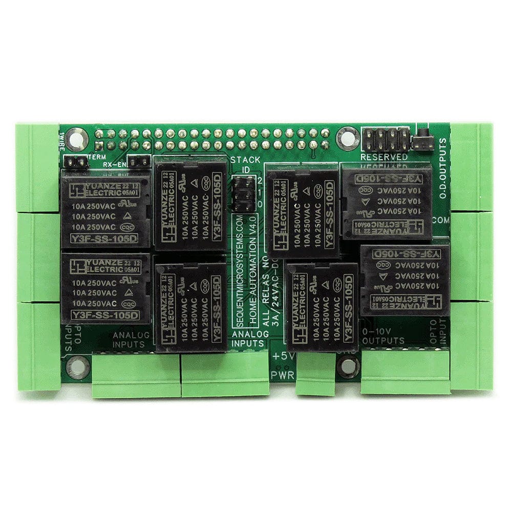
Relays are rated 10A/24VDC and 250VAC, but due to the board geometry limitation, relays 6 and 7 can switch 3A and 24V, while all the others can switch 6A and 24V AC or DC. You can switch larger loads of up to 8A and 240VAC by stacking separate 4-Relays cards, which also adds four extra inputs.
Status LEDs show when RELAYS are ON or OFF.
Up to eight Home Automation cards can be stacked on your Raspberry Pi. Each card is identified by jumpers you install to indicate the level in the stack. Cards can be installed in any order. The three-position jumper on the upper right corner of the card selects the stack level.
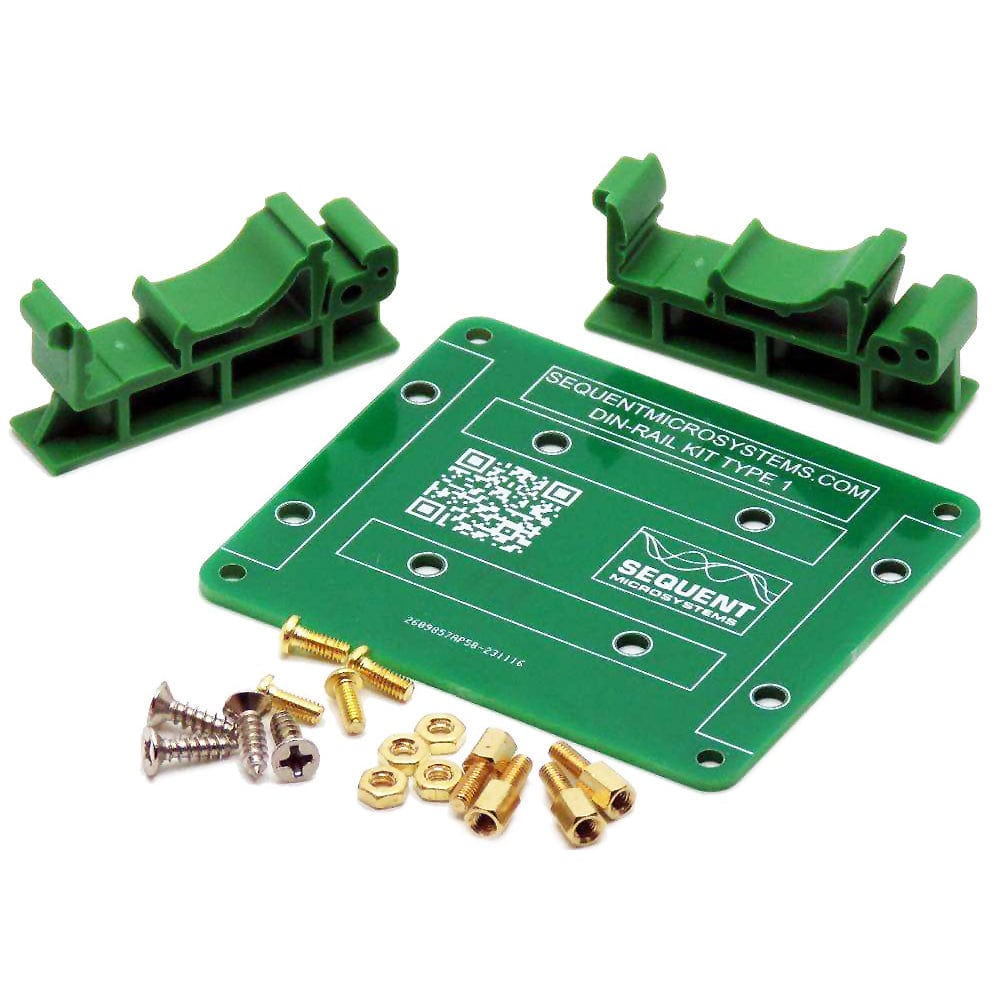
The Home Automation card can be installed parallel on a DIN-Rail using the DIN-Rail Kit Type 1, or perpendicular using the DIN-Rail Kit Type 2.
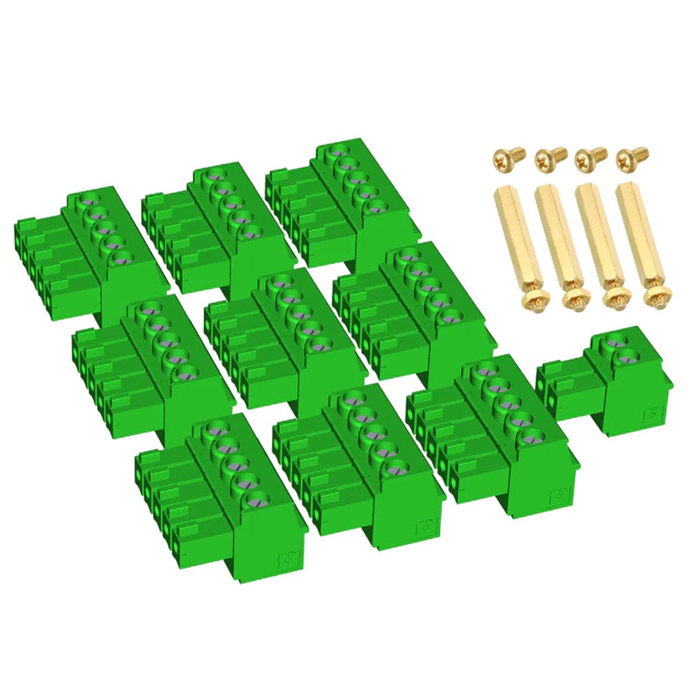
Break-out boards provide a convenient and robust way of accessing the IO pins. For screw-mount wiring, you can use the Break-Out Kit Type 1. The Break-Out Kit Type 2 provides wiring with pluggable connectors.
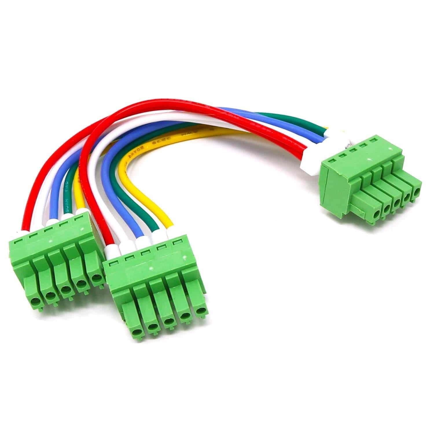
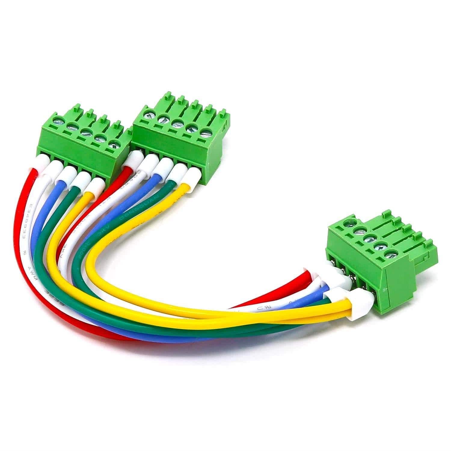
Self-Test Cable
This self-test cable allows you to test groups of three inputs and outputs on the HAT.
You can write your own application using the Command Line or Python Libraries provided. No programming is required if you use the Node-Red nodes we supply. You can drag and drop the functional blocks to design your application. Examples are provided at GitHub.
Groups of three inputs and outputs can be self-tested with the help of a loopback cable. The cable can be purchased or made yourself using three of the connectors provided with the kit. See the software section here for more information.
The analog inputs and outputs are calibrated from the factory with 1% precision. Field calibration up to 0.1% can be obtained using a precision voltage meter. Calibration instructions coming soon.
The card firmware can be updated in the field by running a command. The update is made with the latest firmware version located on Sequent's servers. More instructions about the process can be found on GitHub. Please make sure there is no process, like Node-Red or python scripts, that tries to access the card during the update process.
The Home Automation card contains a built-in hardware watchdog that will guarantee that your mission-critical project will recover and continue running even if Raspberry Pi software hangs up. After power-up, the watchdog is disabled and becomes active after it receives the first reset.
The default timeout is 120 seconds. Once activated, if it does not receive a subsequent reset from Raspberry Pi within 2 minutes, the watchdog cuts the power and restores it after 10 seconds.
Raspberry Pi needs to issue a reset command on the I2C port before the timer on the watchdog expires. The timer period after power up and the active timer period can be set from the command line. The number of resets is stored in flash and can be accessed or cleared from the command line. All the watchdog commands are described by the online help function.
git clone https://github.com/SequentMicrosystems/ioplus-rpi.git
cd /home/pi/ioplus-rpi
/ioplus-rpi$ sudo make install
/ioplus-rpi$ ioplus
The program will respond with a list of available commands.
Your payment information is processed securely. We do not store credit card details nor have access to your credit card information.