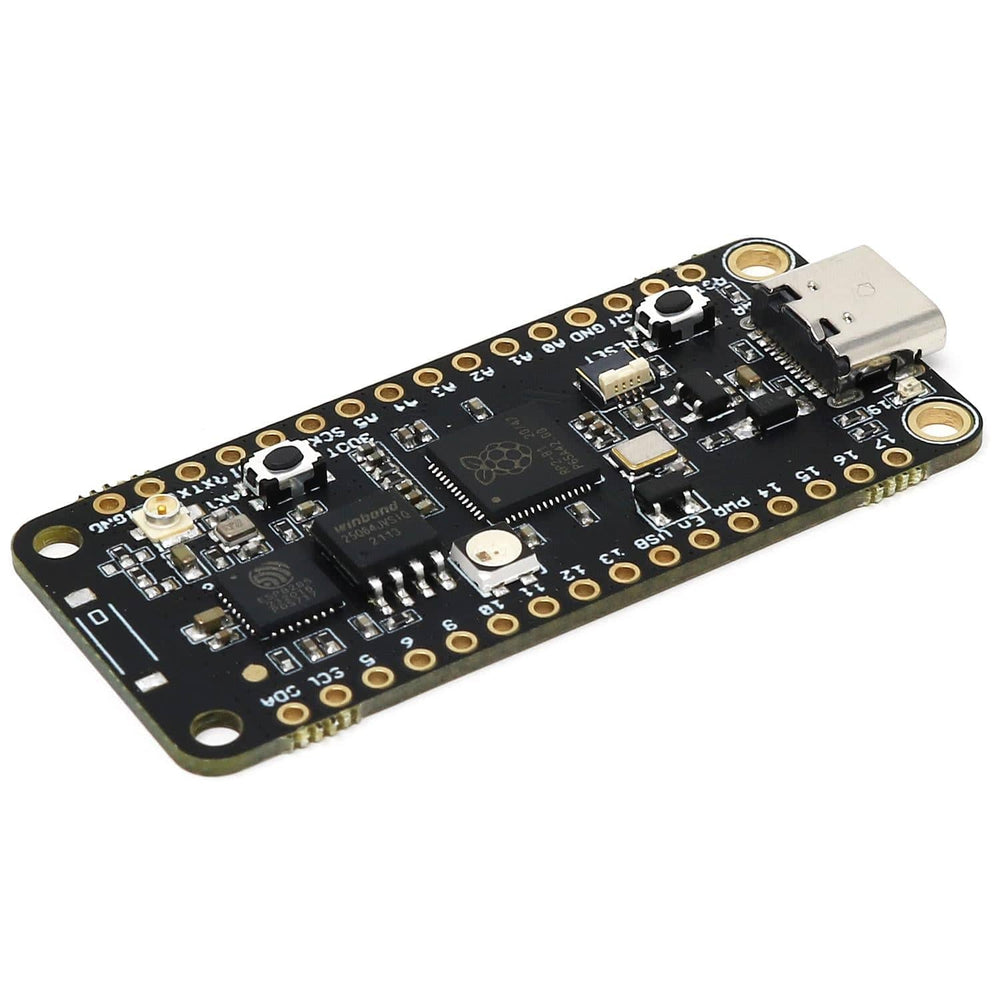
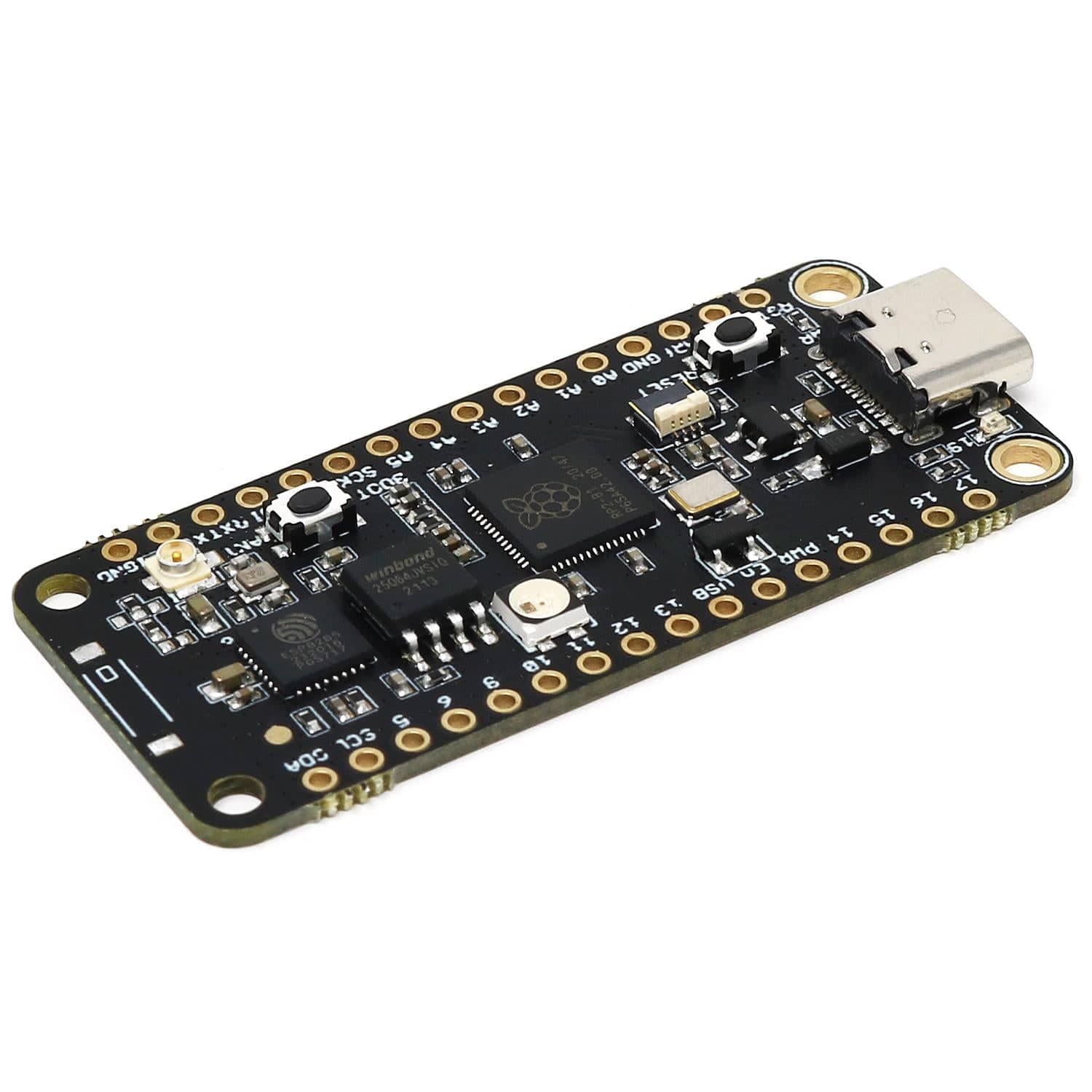
The iLabs Challenger NB RP2040 WiFi (with U.FL connector) is an Arduino/Micropython compatible microcontroller board based on the Raspberry RP2040 chip.
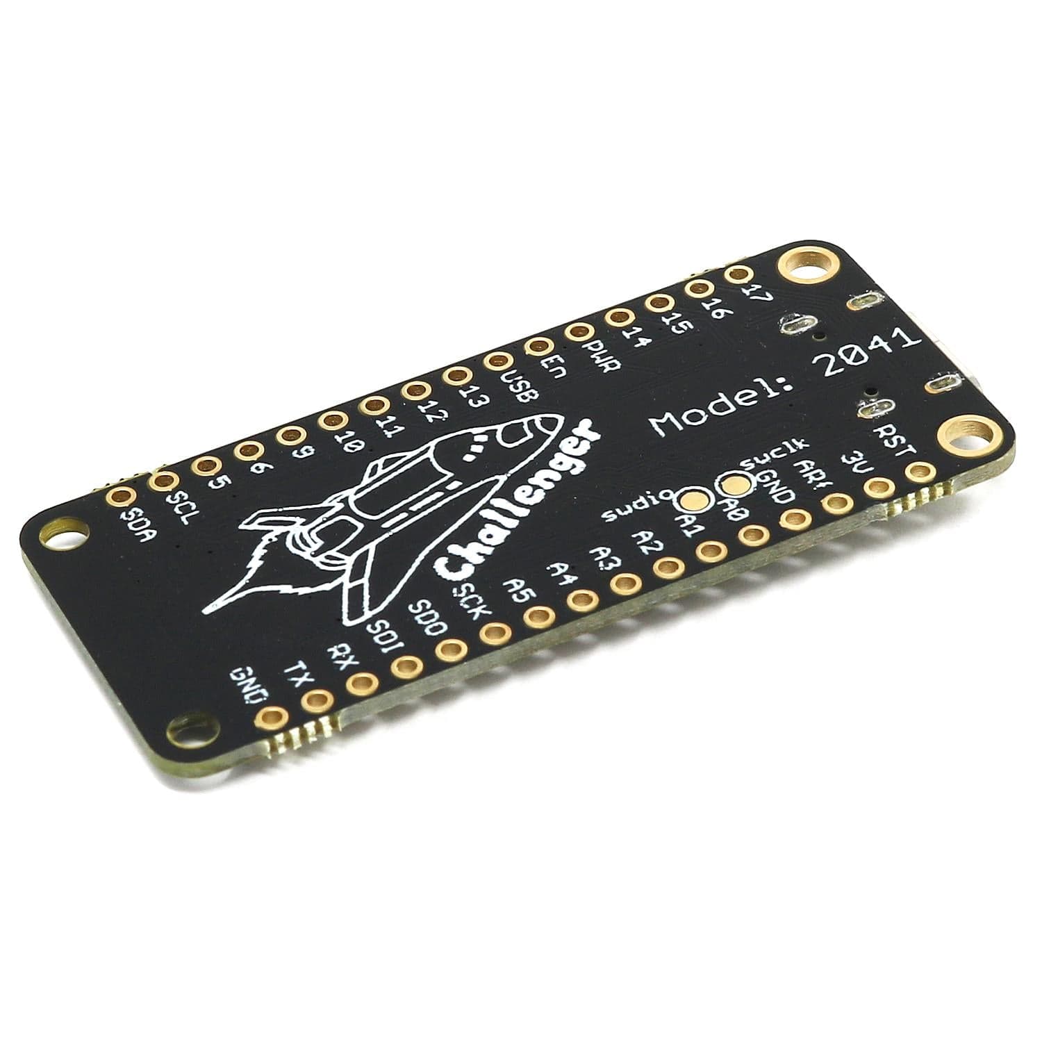
The Challenger NB form factor is largely based on the Adafruit Feather format but with the battery connector and charging circuit removed to allow room for some much-needed extra IO pins. We realized that not all applications require the ability to be powered by a battery and to have the onboard battery charging circuit, so we developed an 'NB' ('No Battery') version of the Challenger RP2040 WiFi board.
We paired the RP2040 with a 8MByte high-speed flash capable of supplying data up to the maximum speed. The flash memory can be used both to store instructions for the microcontroller as well as data in a file system, and having a file system available makes it easy to store data in a structured and easy to program approach.
The WiFi section on this board is based on the Espressif ESP8285 chip which is an ESP8266 with 1MByte FLASH memory integrated onto the chip making it a complete WiFi-only board requiring very few external components. The ESP8285 is connected to the microcontroller using a UART channel and the operation is controlled using a set of standardized AT-commands.
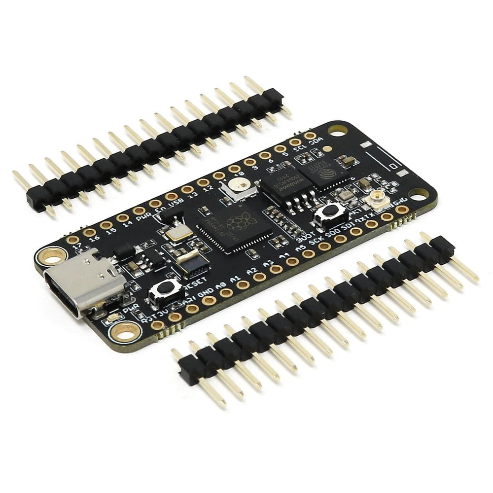
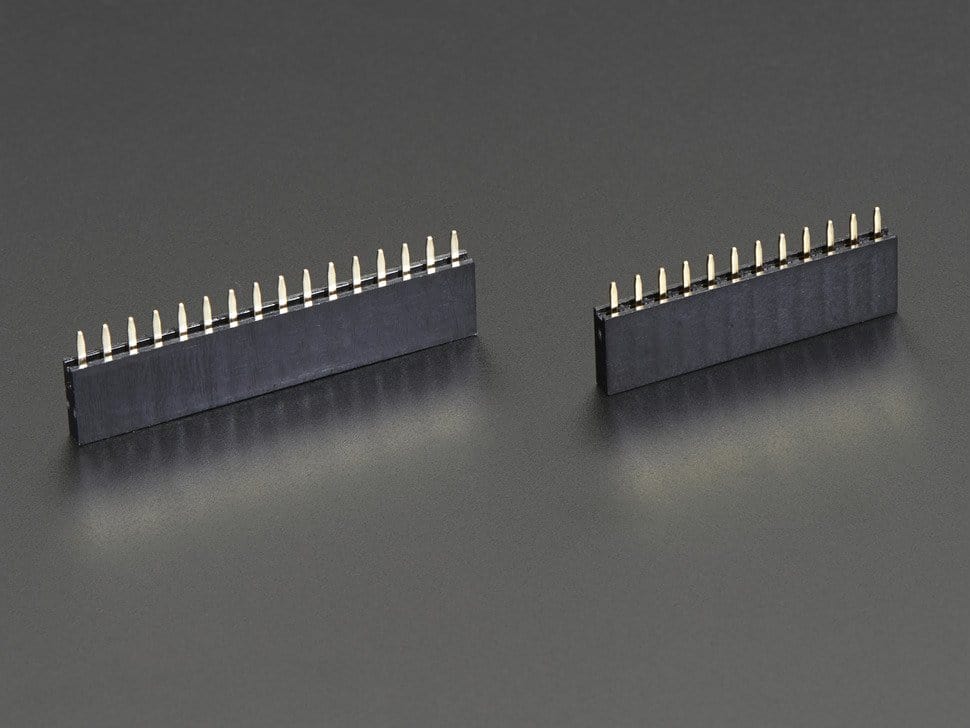
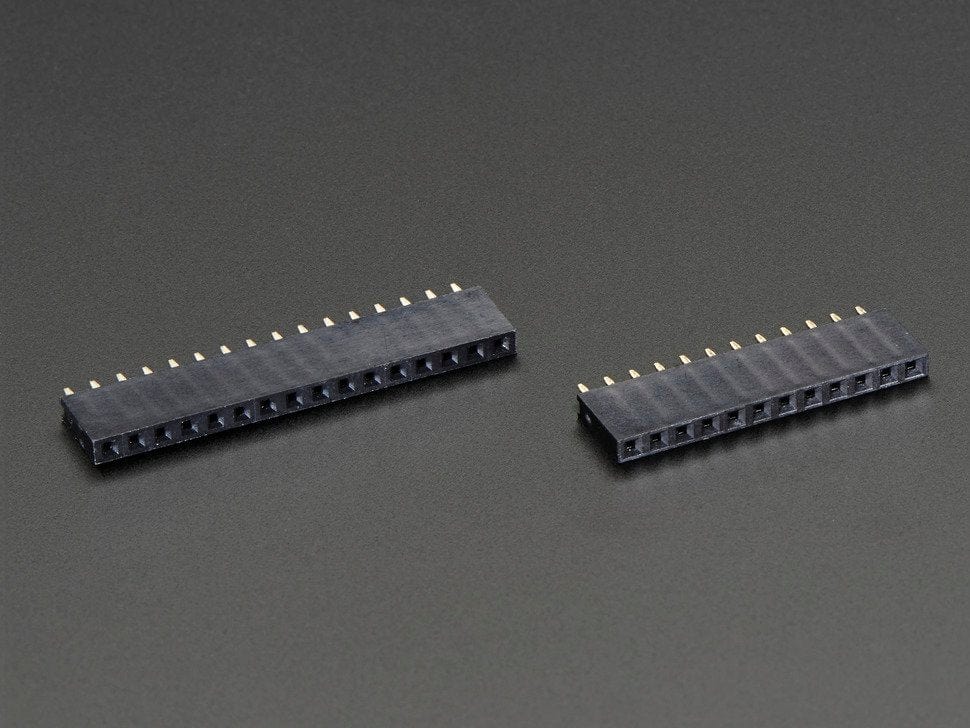
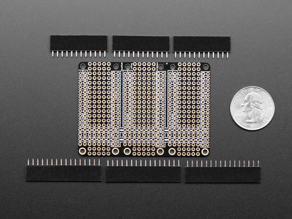
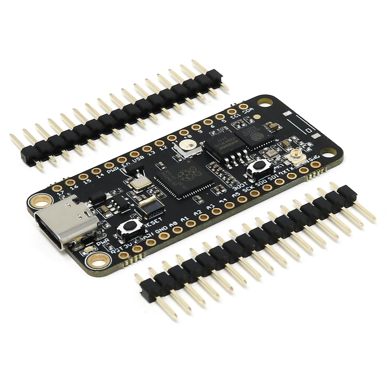
A set of pin headers is included with the board. We also stock a version with an onboard chip antenna rather than a U.FL connector.
WiFi
Just like the Challenger RP2040 WiFi, this board has an ESP8285 WiFi chip. For those of you that are unfamiliar with this device, it is basically an ESP8266 device with an integrated 1MByte of flash memory. This allows us to have an AT command interpreter inside this chip that the main controller can talk to and connect to your local WiFi network. The communications channel between the two devices is an unused UART on the main controller and the standard UART on the ESP8285.
The ESP8285 chip comes pre-flashed with Espressif’s AT command interpreter stored in the internal 1MByte of the ESP8285. This interpreter supports most of the operating and sleep modes of the standard ESP8266 framework which makes it easy to work with. Talking to the device is as easy as opening the second serial port (Serial2), resetting the ESP8285 and start listening for events and sending commands
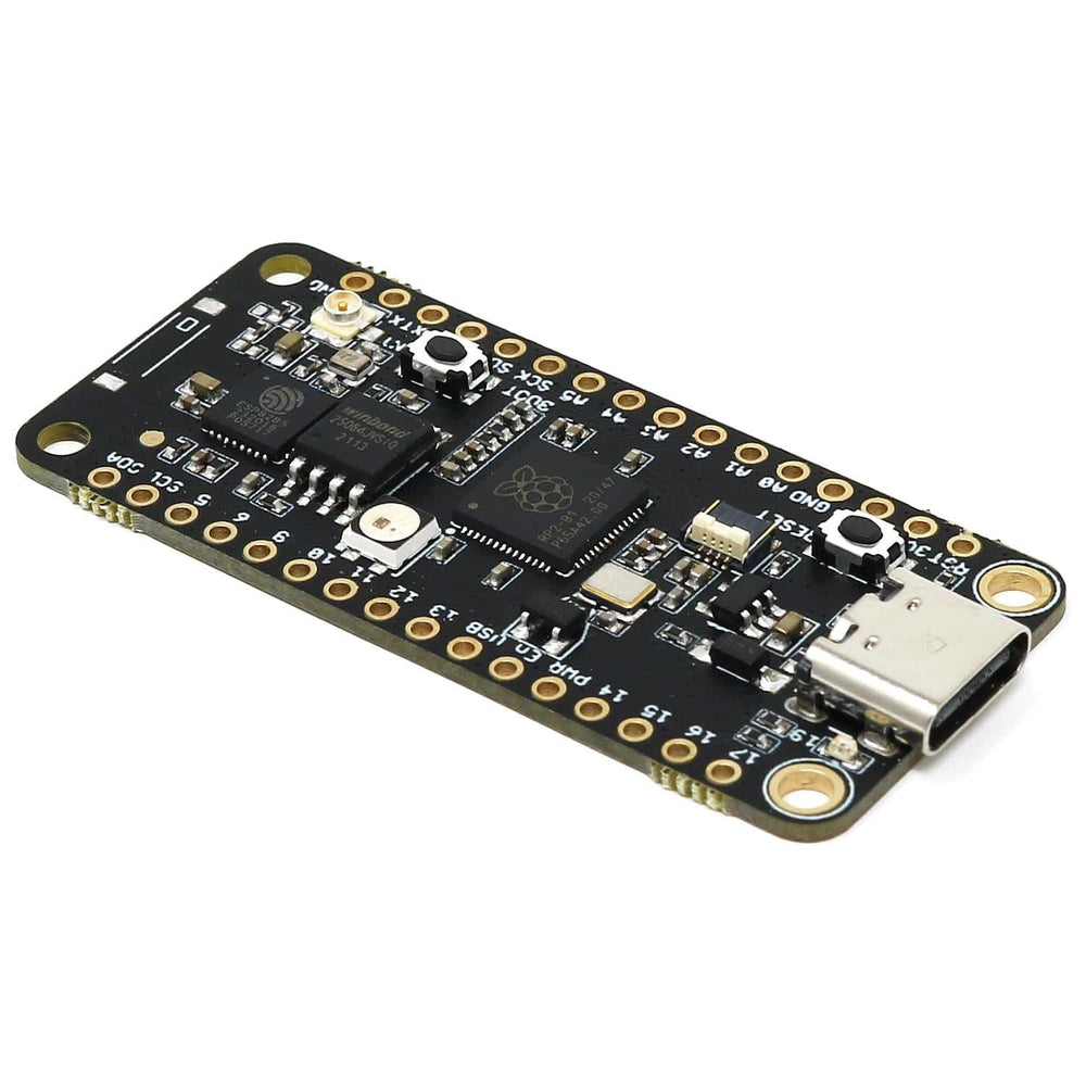
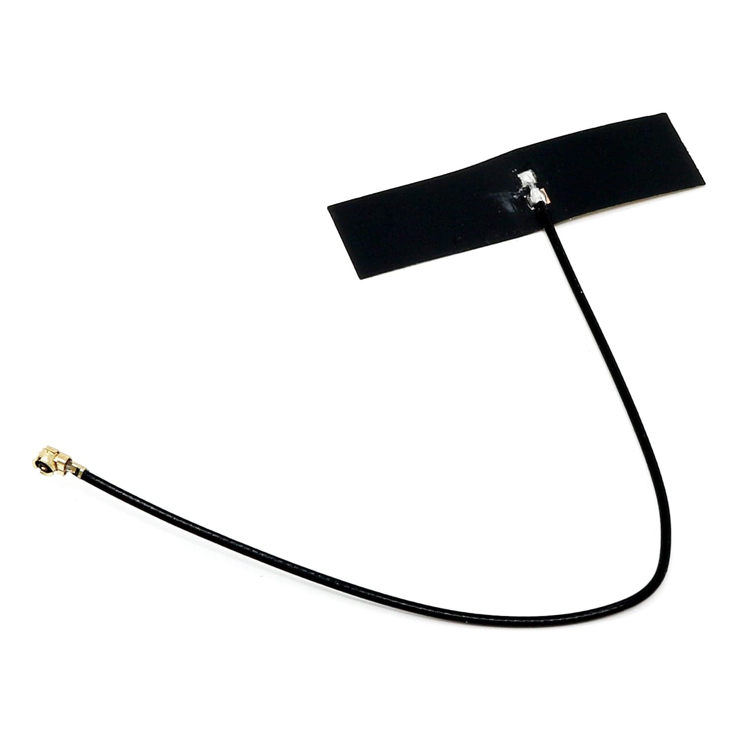
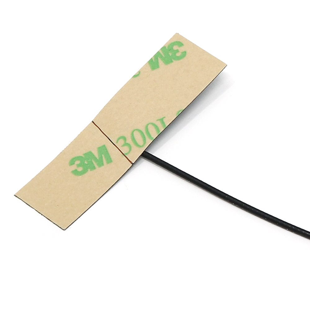
U.FL Connector
This version of the Challenger NB RP2040 has a U.FL connector for adding an external antenna (not included). Care needs to be taken when considering the placement of the external antenna. Depending on the antenna you have selected the antenna manufacturer can give you instructions on what to consider when deciding its placement.
We also offer a version with a chip antenna onboard removing the need for an external antenna (but may have reduced performance depending on project placement).
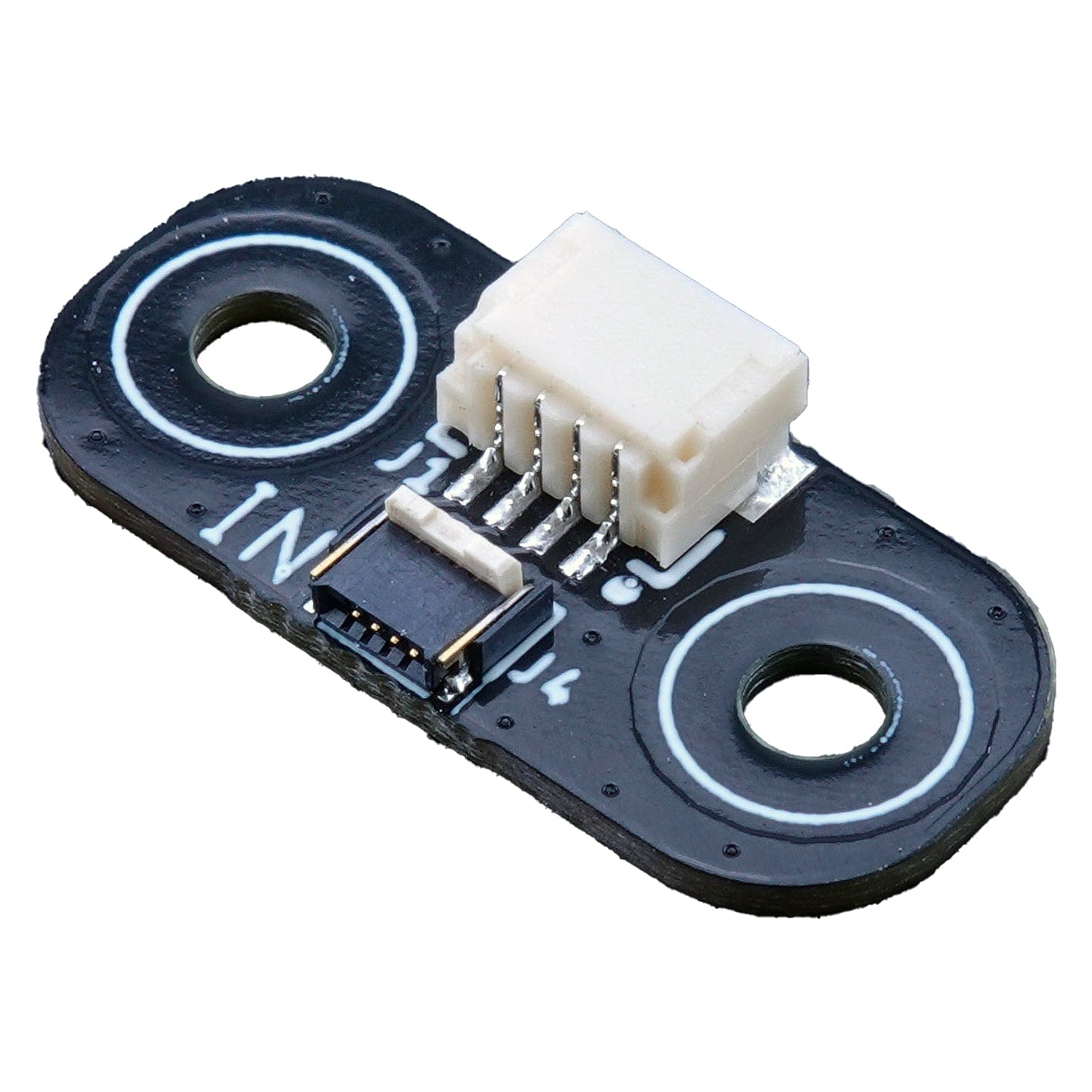
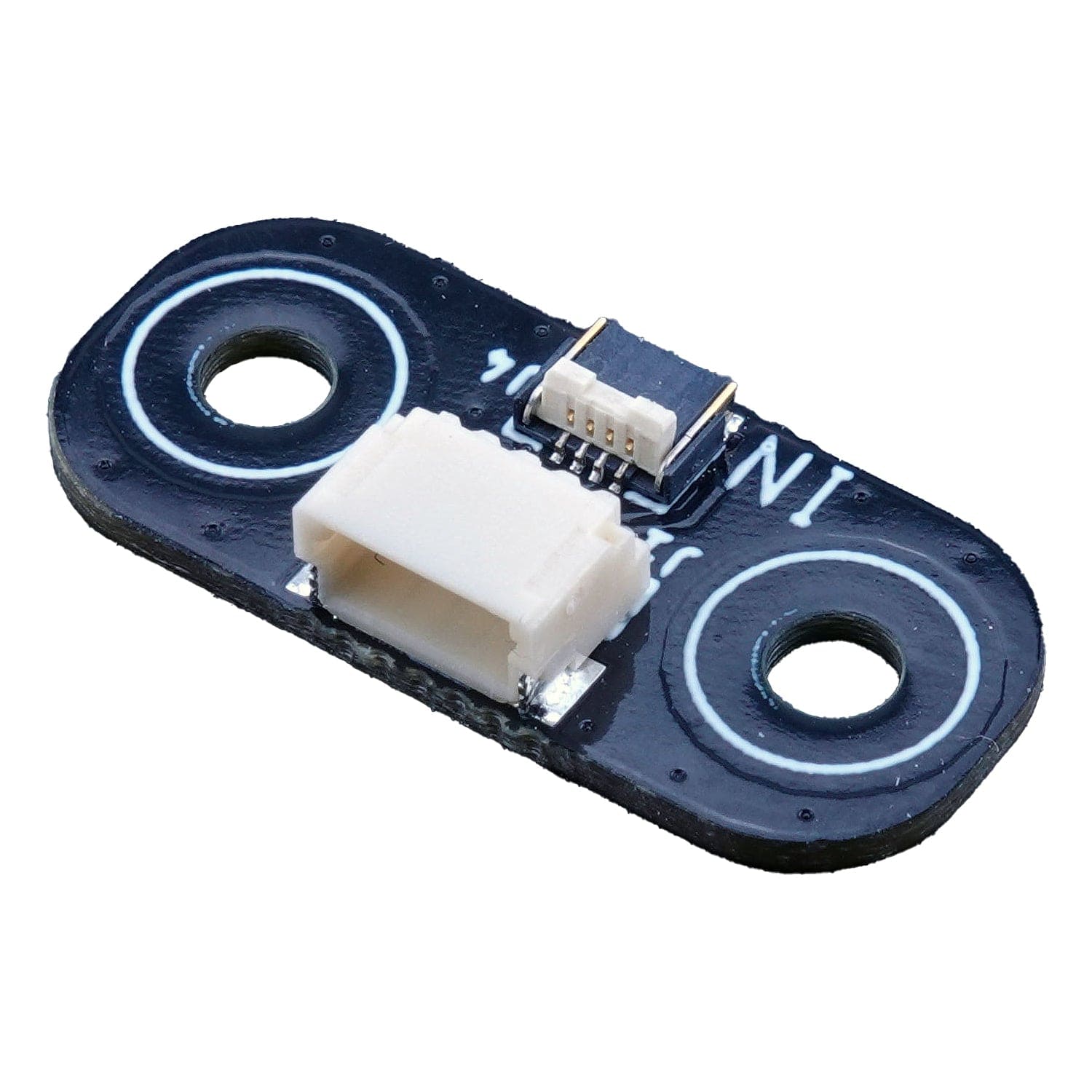
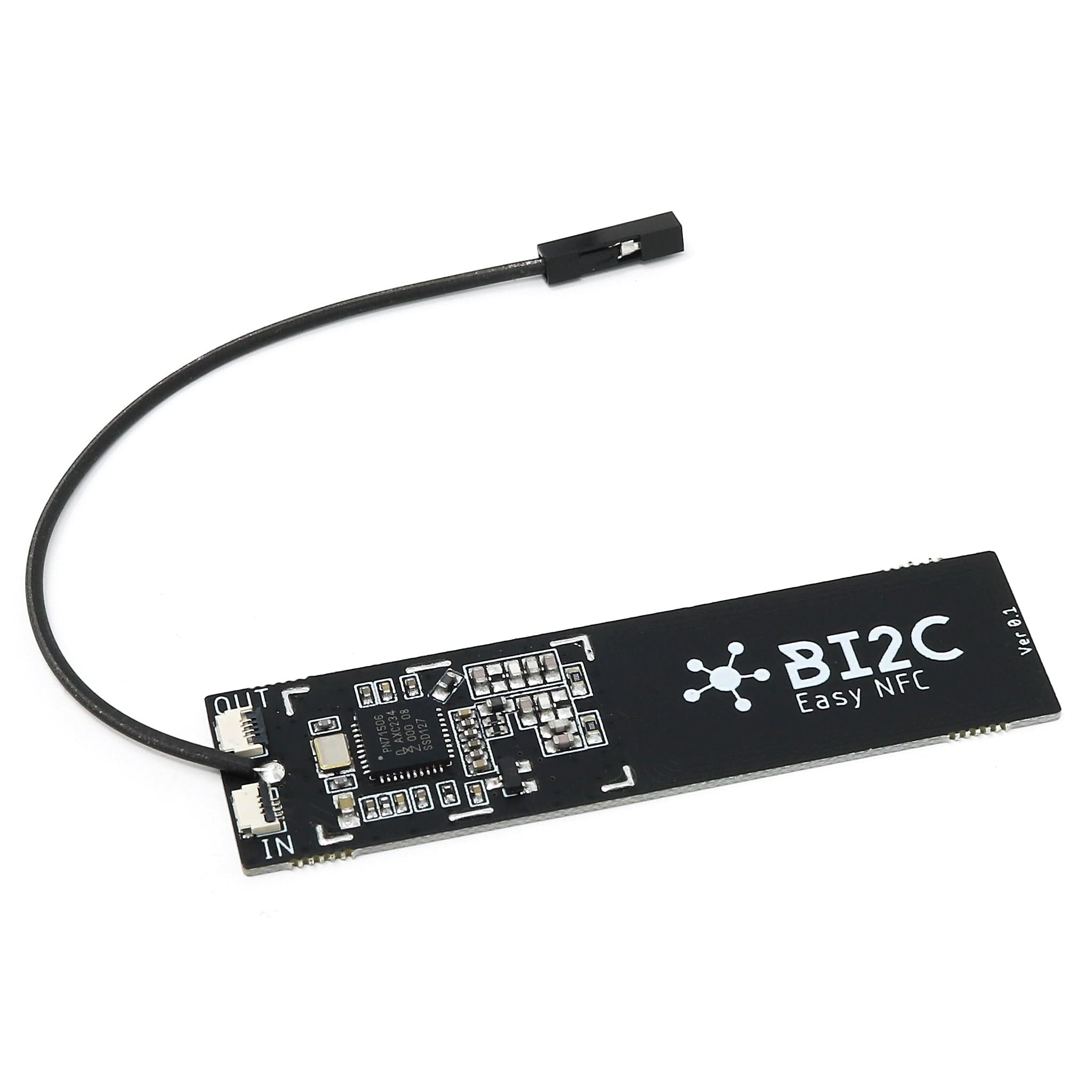
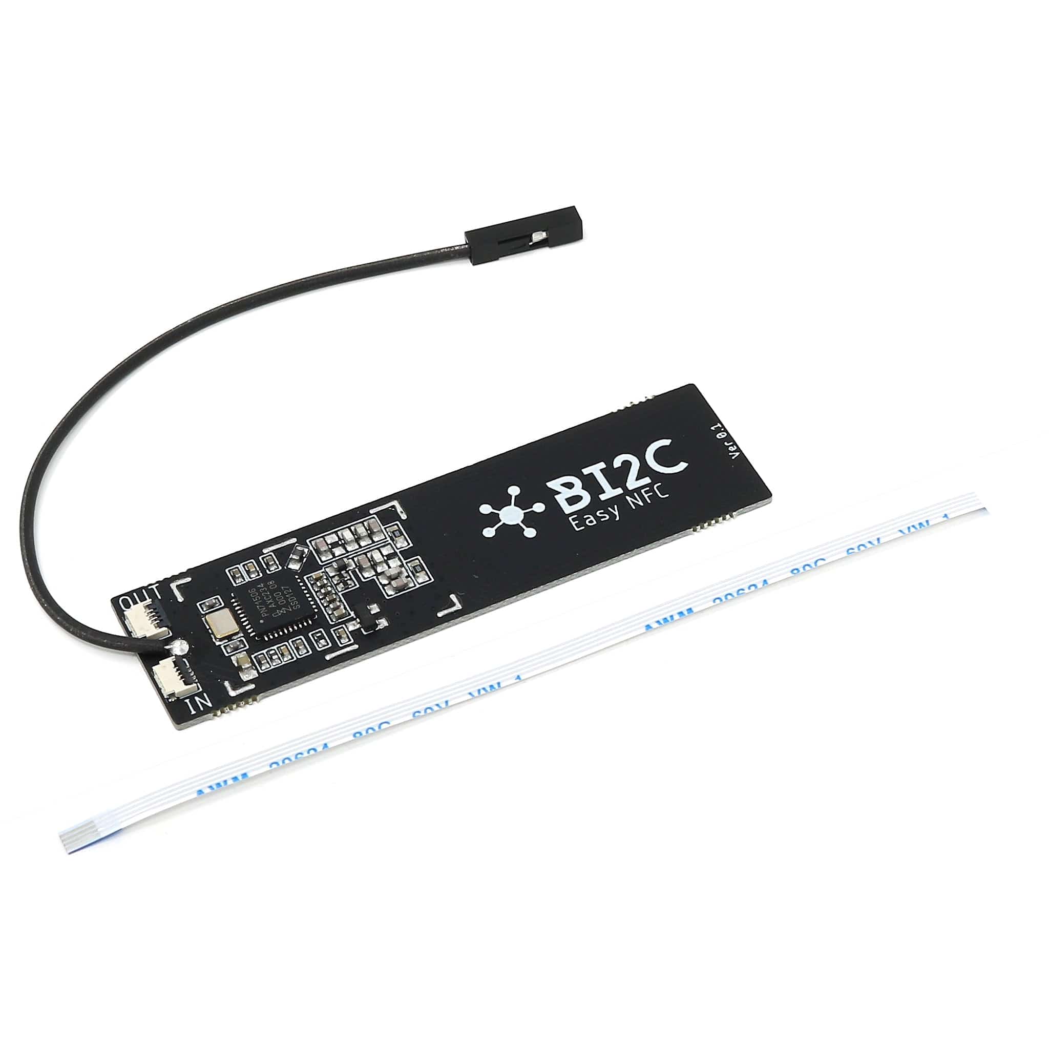
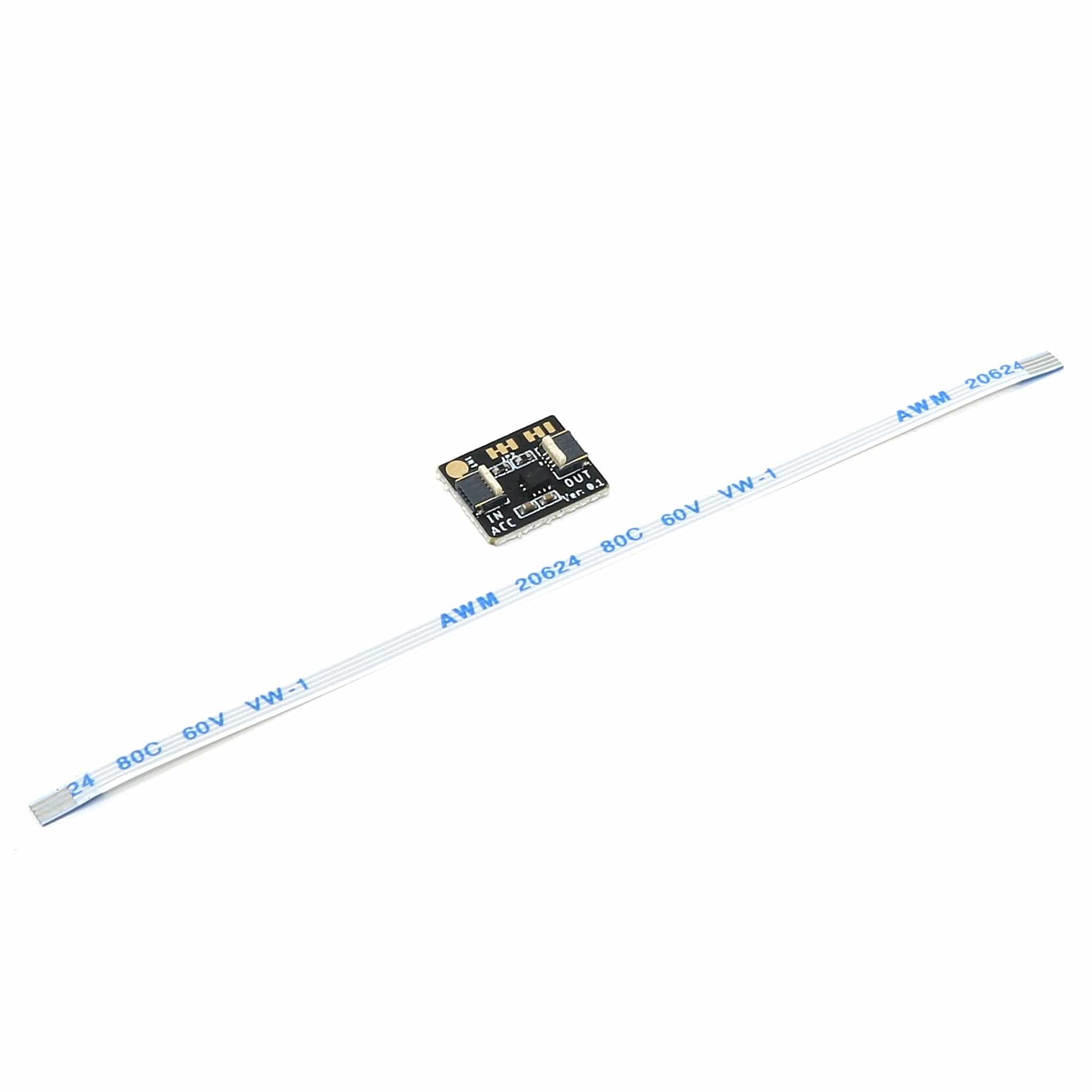
Bi2C Connector
This board includes a Bi2C connector, a small FFC connection used to connect other Bi2C devices (such as the examples listed below).
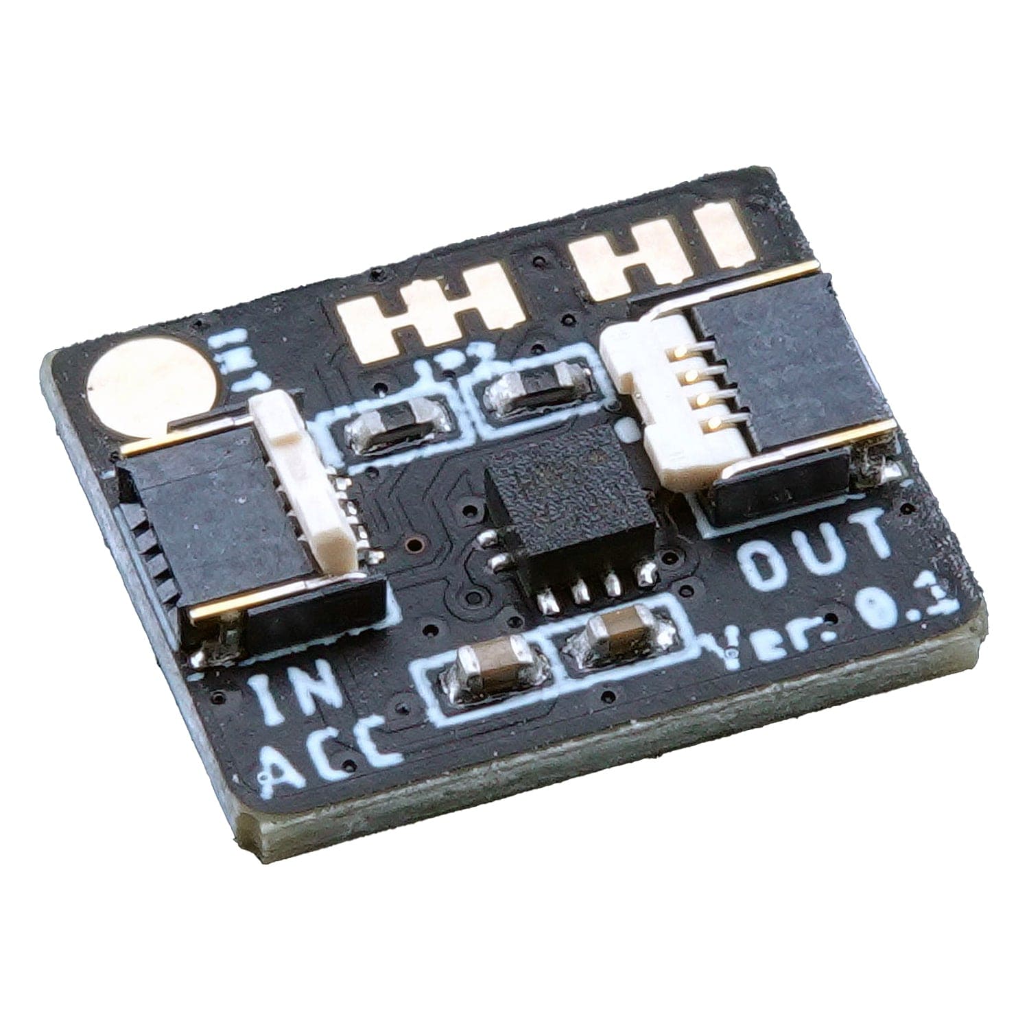
The Bi2C (Bus I2C) concept is a spin-off from the existing Groove, Stemma and Qwiic ecosystems where we use an FFC (Flexible Flat Cable) instead of normal threaded cables to create the connection. This means that we can get away with connectors that have 0.5mm pitch which makes them super thin and compact. Read more about Bi2C here.
You can also use Bi2C with Qwiic/STEMMA QT boards using the Bi2C Qwiic/STEMMA QT adapter, giving you an ultra-thin cable option for compact projects and enclosures.
Power
The board can be powered from multiple sources. The most obvious way to run the board is by plugging it into a USB cable and attaching it to your computer. In this mode, you can write software and test the board with all its functionality.
You can also supply the board with 5V via the header connectors on the PWR pin.
There is a third way to supply the board too. This way is more invasive and will disable the onboard 3.3V power regulator. When doing this you will have to pull the EN header pin low and then supply your own 3.3V voltage on the 3.3V header pin. Please note that when disabling the onboard power regulator you will have to supply the 3.3V also when running the system on battery power.
LEDs
On each side of the USB connector, there is a small indicator LED. The LED which is marked PWR is a power-on indicator, this is a green LED that will light as long as the board has power applied to it. On the other side of the USB connector, there is a user-programmable yellow LED. This LED is connected to pin D15 (LED_BUILTIN) and can easily be controlled by the user.
Finally, there is a NeoPixel-compatible LED on the board. This is an RGB LED with intensity control, run by a single GPIO pin on the board. There are several good example libraries that can be used to drive this LED.
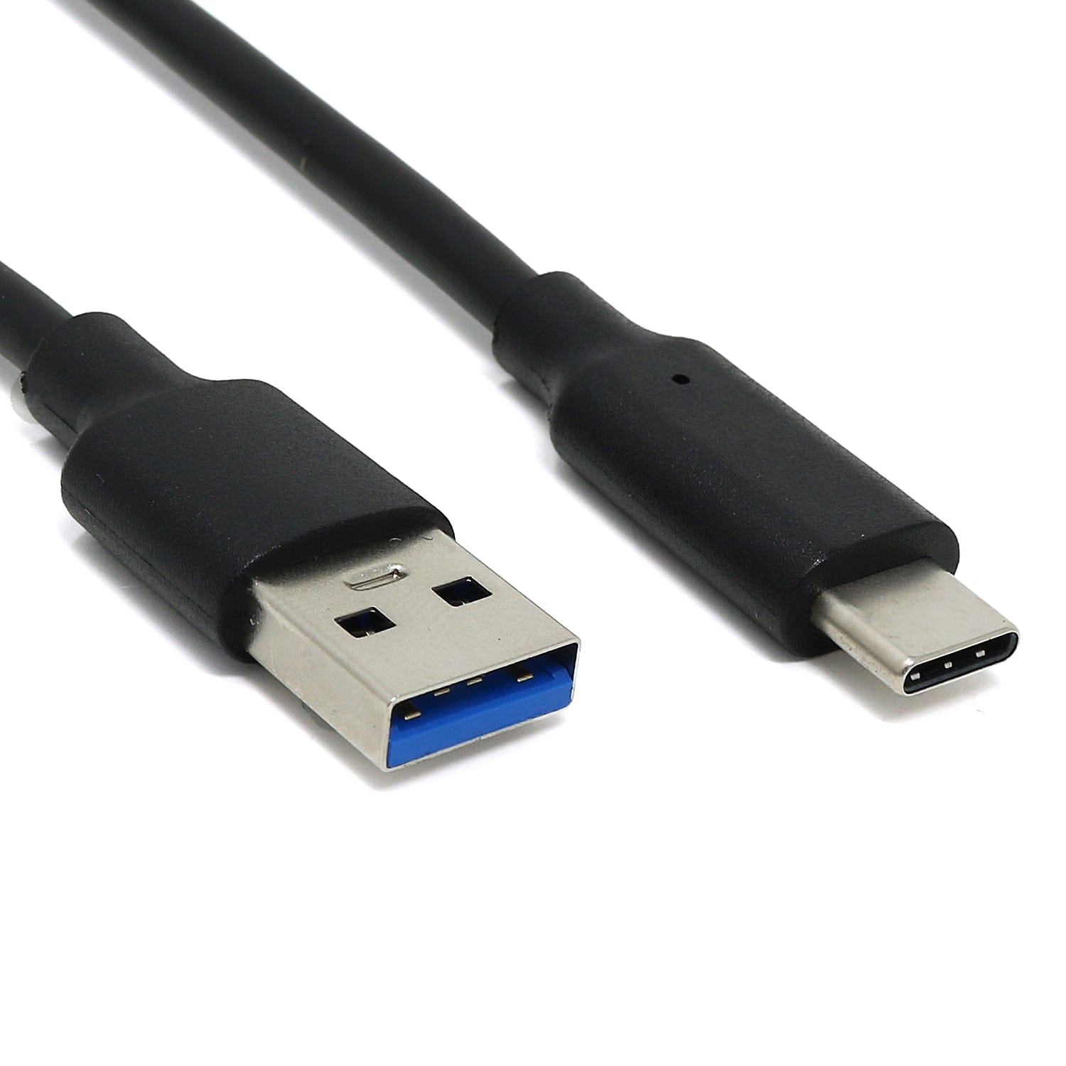
USB Type-C
In recent years we have noticed that we are seeing more and more USB Type-C cables laying around the lab due to the fact that most new phones and accessories use them. So iLabs decided to go for a USB Type-C connector for this board. A bonus of this is that they are more durable and you don’t have to fiddle with the cable before plugging it in!
Connection between MCU and ESP8285 WiFi controller.
The board uses the second UART (UART 1) of the MCU to connect to the ESP8285 as well as two GPIO pins that allow the RP2040 to reset and put the ESP8285 in flash mode. The pins used are as follows.
-
GPIO4 acts as UART1 TXD
-
GPIO5 acts as UART1 RXD
-
GPIO19 is connected to ESP8285 reset and is active low (PIN_ESP8285_RST in the Arduino IDE).
-
GPIO13 Is connected to the mode pin of the ESP8285. If it is pulled low at the same time the reset signal is going high the chip will enter flash mode (PIN_ESP8285_MODE in the Arduino IDE).
The WiFi chip runs an internal AT interpreter, over the UART lines, to do all the wireless communication. It supports baud rates up to 921600 bits/s allowing the system to have a throughput of up to 500Kbit/s TCP traffic and up to 1MBit/s UDP messaging.
Features
- RP2040 Dual Core Cortex-M0 @ 133 MHz
- 8 MByte FLASH Memory
- 264 KByte SRAM Memory
- 1 Hardware I2C channel
- 1 Hardware SPI channel
- 1 Hardware UART for the user (Serial1)
- 1 Hardware UART connected to the network processor (Serial2 @ 1Mbit/s)
- 12 Bit ADC
- ESP8285 with internal 1MByte FLASH Memory
- WiFi (2.4 GHz)
- Espressif AT interpreter
- Communicates at 921600 bits/s
- NeoPixel-compatible LED
- USB-C connector
-
U.FL connector (no onboard antenna)
Specifications
| Description |
Value |
Comment |
| Board Size |
50.80 mm x 22.86 mm x 3.20 mm |
USB protrudes ~1mm |
| Main microcontroller |
RP2040 from Raspberry Pi |
133MHz dual core Cortex M0 |
| SPI |
One SPI channel configured |
|
| I2C |
One I2C channel configured |
|
| UART |
One UART channel configured |
Second UART for the WiFi chip |
| Analog inputs |
4 analog input channels |
|
| WLAN controller |
ESP8285 from Espressif |
160MHz single core Tensilica L106 |
| FLASH Memory |
8MByte 133 MHz |
|
| SRAM Memory |
264KByte |
Divided into 6 banks |
| USB 2.0 controller |
Up to 12MBit/s full speed |
Integrated USB 1.1 PHY |
| NeoPixel-compatible LED |
RGB LED |
|
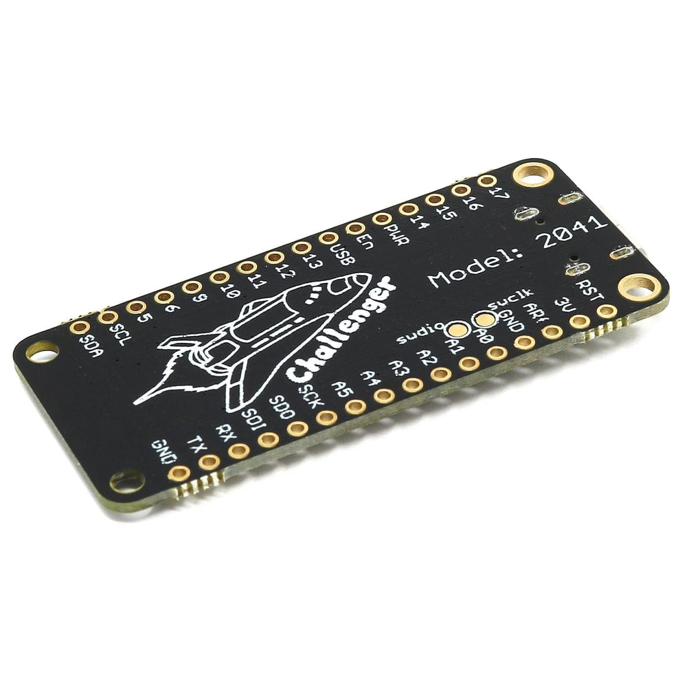
Pinout
The RP2040 has a number of communication channels that have been routed out to the side (header connector) connectors.
-
UART – One UART channel has been routed to the header pins (RX, TX). The microcontroller has 2 UARTs, on this board the second UART is used for communicating with the WiFi chip
-
SPI – One SPI channel has been routed to the header pins (SCK, SDO, SDI)
-
I2C – One I2C channel has been routed to the header pins (SCL, SDA)
-
Analog pins – The microcontroller has 4 analog input pins that all are available on the header pins (A0-A3)
-
PWM – All pins can be used for PWM
The pin chart below shows the placement of all pins and their respective functions. When working in an Arduino environment (or Platform IO) use the blue pins, and when writing your code and working with CircuitPython use the orange marked pin assignments.

Resources
Using the Arduino environment
iLabs teamed up with Earle F. Philhower over at his Github page to provide Arduino support for their RP2040/Pico based boards. All instructions on how to install the board support package as well as multiple examples on how to use the Raspberry Pi Pico processor.
MicroPython
The Challenger RP2040 WiFi board is fully compatible with both the micropython package found at the Raspberry Pi site as well as Adafruits CircuitPython.
Instructions on how to install the python interpreter of your choice are available on the respective websites.
Package Contents
- 1x Challenger NB RP2040 WiFi Board (U.FL Connector version, no onboard antenna)
- 2x Pin headers