Getting Started with the Elecfreaks Pico:ed
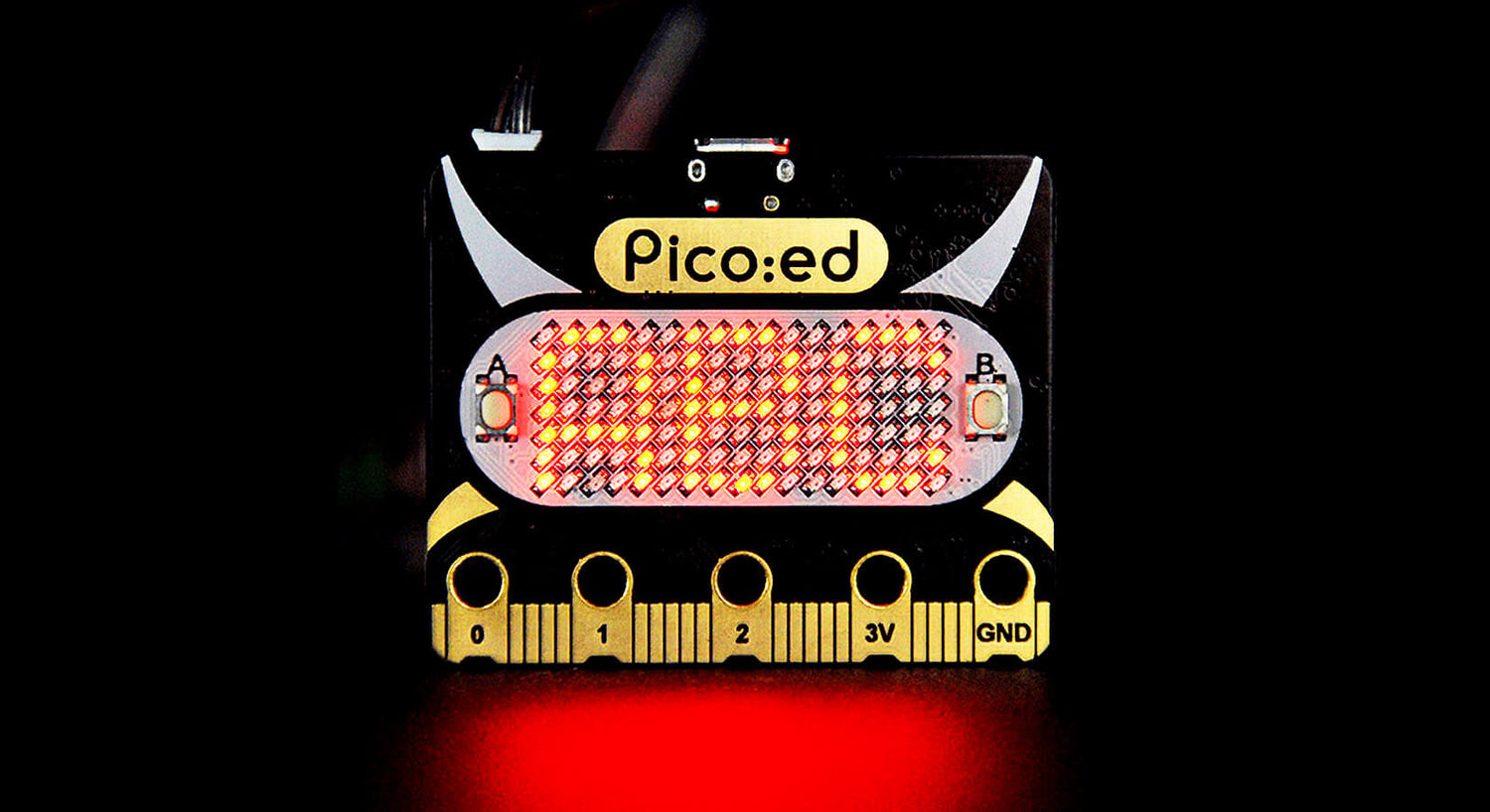
The Pico:ed is a development board based on Raspberry Pi RP2040 (the chip used on the Raspberry Pi Pico) but with the form factor of the very successful BBC micro:bit. The 'ed' part of the name stands for education.
The front of the board sports two buttons, an LED hidden in the dot of the ‘i’ in 'Pico', and a large, bright 7x17 dot matrix display. The rear has a small speaker for tones and beeps, a boot button for updating the device with a newer UF2 file and a power socket for a battery pack allowing use away from the computer.
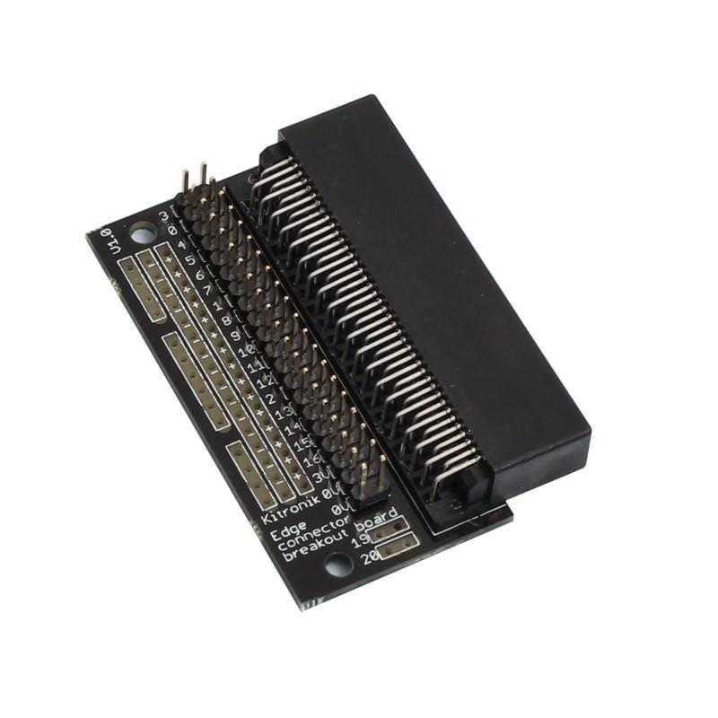
The edge connector allows the user to interface, via alligator clips or an edge connector breakout board, with a wide variety sensors, displays, micro:bit add-ons and starter kits such as the Elecfreaks micro:bit Starter Kit or Kitronik Inventor’s kit.
The well supported RP2040 microprocessor can be programmed with the easy to learn and very popular MicroPython language using the free Thonny editor. This makes it an ideal starting board from those not interested in programming with blocks. There is enough of memory provided with 256KB of SRAM and 2MB of Flash memory for quite large projects!
This tutorial will cover
- Updating the board by adding the device library
- Flashing the built-in LED
- Using the buttons
- Showing text and numbers on the display
- Playing a tune
- Learning how to control the individual pixels on the display
- Sensing distance with an external IR sensor and displaying the value graphically on the display.
- Connecting potentiometers to control the display
- Adding an SSD1306 display for more advanced output
What you’ll need
- Elecfreaks Pico:ed board
- Micro-USB cable for power and programming
- Thonny installed on your computer
- Ability to enter, edit, save and execute MicroPython code using Thonny
- Optional
Getting started
The manufacturer provides some starter documentation on their website.
The pinout diagram shows that:
- The single LED is on GP25
- Button A is on GP21
- Button B is on GP22
- GP0 to GP3 and GP17 to GP25 are not brought out
The edge connector has fewer physical pins as some will be needed to drive the buzzer on GP0 and the matrix display on GP18/GP19 via I2C with a chip address of 0x74.
The site explains how to download the zipped file and save the device driver program in the lib folder on your Pico:ed. After following the instructions playing with the examples we finished up with the file windows of Thonny looking like this (do not bother with creating and saving the Main.py file at the moment):
Example programs
There are 4 very simple examples provided by Elecfreaks to get you started. You can copy them from the web site, paste them into new code windows, save, execute and experiment:
- Control the LED by the buttons – Turn ON/OFF
- Scroll letters and numbers via the buttons
- Play a few tones as a tune
- Connect an external LED and control via buttons.
Unfortunately, there is no example about how to control the display! We need to be able to turn individual pixels on and off and to control the brightness. This isn't covered by the manufacturer's examples so we'll show you how later on in this tutorial!
Exploring the Examples
We need to look in detail at the library code to see if we can work out what is going on in each example. You can print out the code directly from Thonny or from the Python 3 IDE. The latter shows some extra comments in the ‘Music’ section...
Music
This is the provided example, with some mystery #'d out comments in a language we're not fluent in!

Time for Google to save the day and translate the comments for us. Here's what we found:
- self.buzzer.duty_u16(1000) #Adjust the frequency of the PWM so that it emits the specified tone
- self.buzzer.duty_u16(0) #No power on when shooting empty
- #Pause (two tones per second in four or four beats, with a slight pause in the middle of each syllable)
- self.buzzer.duty_u16(0) #The duty cycle of the device is 0, that is, it is not powered on
- self.buzzer.deinit() #release PWM
This explains that Pulse Wave Modulation (PWM) is being used to generate a square wave to make tones on the speaker. Looking at the frequencies given in the dictionary of tones we see that there are 7 notes in C major – starting at ‘middle C’.
self.tones = {'1': 262, '2': 294, '3': 330, '4': 349, '5': 392, '6': 440, '7': 494, '-': 0}The ‘–‘ symbol provides silence. It would be easy to add extra tones/notes. Check out the links below for the required frequencies:
- https://www.doctormix.com/blog/note-to-frequency-chart
- http://www.sengpielaudio.com/calculator-notenames.htm
Text and numbers for the display
Here we notice that only the letters, numeric characters and ‘space’ are defined in another dictionary. The list for each character is the co-ordinates of the pixels making up that letter, starting at the top:
"i":[[2,0], [1,2], [2,2], [2,3], [2,4], [2,5], [1,6], [2,6], [3,6]],
"j":[[3,0], [2,2], [3,2], [3,3], [3,4], [0,5], [3,5], [1,6], [2,6]],
Try plotting out these co-ordinates to see how they work.
Pixels
Here is the code block in the example file for pixels:def pixel(self, x, y, color=None, blink=None, frame=None):
if not 0 <= x <= self.width:
return
if not 0 <= y <= self.height:
return
pixel = self._pixel_addr(x, y)
The top line gives us the clue to the basic pixel instruction. Where (x, y) is the pixel position in relationship to the top left corner of the screen (0, 0) and c is the colour/brightness in the range 0 to 255.
Notice that the procedure will return without doing anything if the given position does not relate to a physical LED on the display. This is very helpful – an off-the-display pixel instruction will not cause an error.
display.pixel(-3, 12, 5)
This instruction will do nothing. The error trapping makes programming much easier.
An example program testing our findings
We suggest that you copy the program below and paste it into Thonny. Save it as GFX.py and run it. The script has many comments to help you understand what is going on.
In the ‘bounce’ section, pressing button ‘A’ stops the looping by re-setting the running variable to False.
# Pico:ed GFX demonstration in 17x7 pixels
# By Tony Goodhew 30 April 2022 for thepihut.com
from Pico_ed import *     #import Driver library
import utime
delay = 0.1

#Brightness
display.fill(1)  # Fill display with pale pixels
utime.sleep(2)
display.fill(10) # Fill display with brighter pixels
utime.sleep(2)

# Lines
display.fill(0) # clear the screen to BLACK
for i in range(7):  # Vertical line in column 0
    display.pixel(0,i, 10) # pixel ON
    utime.sleep(delay)
for i in range(7):
    display.pixel(0,i, 0) # pixel OFF
    utime.sleep(delay)
for i in range(17): # Horizontal line
    display.pixel(i,3, 10) # pixel ON
    utime.sleep(delay)
for i in range(17):
    display.pixel(i,3, 0) # pixel OFF
    utime.sleep(delay)

# Brightness 2
# Single pixel getting brighter
for i in range(255):
    display.pixel(3,3, i)
    utime.sleep(0.01)
# Line of pixels getting brighter
step = int(255/16)
for i in range(i):
    display.pixel(i,5, i * step)
display.pixel(16,5, 255)
utime.sleep(2.5)
display.fill(0)

# Pretty edge - Some pixels off the screen without error
c = 10 # colour/brightness
for i in range(17):
    display.pixel(i,0, c)
    display.pixel(17-i,6, c)
    display.pixel(0,i, c)
    display.pixel(16,7-i, c)
    utime.sleep(0.1)
utime.sleep(1)

# Pixel Bounce
display.show("Pixel Bounce")
display.show("Press A to Halt")
dx = 1
dy = 1
running = True
x = 3
y = 3
while running:
    display.pixel(x,y, 10) # Current pixel ON
    utime.sleep(.05)
    oldx = x
    oldy = y
#    print(x,y) # Old debug help - slows down bouncing
# Update pixel position - not displayed yet
    x = x + dx
    if x  == 17:
        x = 15
        dx = -1
    if x == -1:
        x = 1
        dx = 1
    y = y + dy
    if y  == 7:
        y = 5
        dy = -1
    if y == -1:
        y = 1
        dy = 1
    display.pixel(oldx,oldy, 0) # Turn pixel OFF
    # Press button A to stop
    if ButtonA.is_pressed():
        running = False
display.fill(0)

display.show("Bye")
utime.sleep(2)
display.fill(0) # clear display
Extra notes
- The colour is really brightness - all the pixels are RED. 1 is rather too dim and 10 appears to us to be a useful norm. 255 is over-bright.
- The error trapping for off-the-display pixels works very well – see the Pretty Edge section.
- Notice that in the bouncing section we light up the pixel and save its current position in oldx and oldy. We then update x and y and only turn the pixel off at the bottom of the loop. The new pixel is then lit at the start of the next loop. A pixel is ON for more time than OFF.
- A print statement to the Shell Window in Thonny is very slow while running a graphics loop. Try uncommenting: # print(x,y) # Old debug help - slows down bouncing
- Displaying a text string on the display scrolls if there are more than 3 characters but is stationary with 3 or less
Practical Example – IR Distance Sensor
This simple IR sensor is available to buy on its own or as part of the Waveshare Sensors Pack.

This sensor has an Infra-Red LED as transmitter and an Infra-Red receiver in the black extension of the board. The voltage on the AOUT pin varies with the amount of light that is reflected back into the receiver.
If we connect AOUT to one of the Analogue to Digital Converter pins on the board we obtain a reading which changes as we move a piece of white paper towards and away from the sensor. The DOUT pin provides a 0/1 output and the threshold is adjustable with the tiny onboard potentiometer. The LED toggles as the threshold is passed. The other LED is a power indicator.
We used an Edge Connector Breakout Board to make hooking this up easier, but you could use crocodile clips or similar.  The short program below enabled us to display a pixel moving across the display to represent the distance between the sensor and the piece of paper:
# Pico:ed Infra Red  Sensor and GFX demonstration in 17x7 pixels
# By Tony Goodhew 30 April 2022 for thepihut.com
from Pico_ed import *     #import Driver library
import utime
import machine
# Connections
#   VCC - 3.3V
#   GND - GND
#   AOUT - 0 = GP26 = ADC 0
adc = machine.ADC(26)
old_ir = 0
while True:
    ir = int(adc.read_u16()/3500)-1
    display.pixel(old_ir,3, 0) # pixel OFF
    display.pixel(ir,3, 10) # pixel ON
    old_ir = ir
Connecting potentiometers to control the Pico:ed display
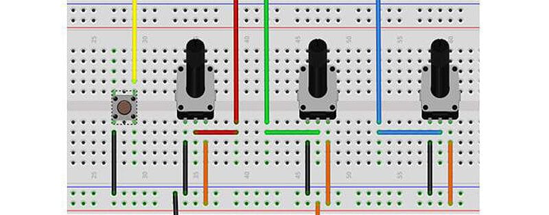
Try connecting some 10k potentiometers to your Pico:ed board to control pixels! Below is a wiring diagram showing how to hook these up.
The colours are as follows:
- Red to ADC0
- Green to ADC1
- Black to GND
- Orange to 3.3 volts
Things to try
Use the information in this tutorial and other resources to try and code the following suggestions. Remember that you have a standard Raspberry Pi Pico RP2040 MCU on the Pico:ed board, so most of the published material (in books and on the internet) for the Pico will work with it:
- Control the position of a bright pixel on the display with the two potentiometers. Use one for horizontal values (0-16) and the other for vertical (0-6).
- Add to the previous program to make a game. Steer the pixel to ‘bump’ a randomly positioned target pixel with a different brightness. Beep when bumped!
- Time how long this takes and display the time.
- Write some additional tunes.
- Add extra tones/notes in the dictionary of the library if needed such as sharps and flats or increased range.
- Show negative numbers on the display. Count from – 20 to +20.
- Method 1: display a space before the digits and then draw in the minus if needed
- Method 2: add a minus character to the dictionary of characters in the library
Using a graphical OLED SSD1306 display with the Pico:ed
The popular SSD1306 display comes in two sizes, 128x32 and 128x64 pixels and in several formats. They all use the same i2c connection (usually - see more on this below), with only four wires.
- VCC – 3.3V
- GND – GND
- SDA – GP8
- SCL – GP9
We need to install a driver library. The GitHub page is here, or you can just download the library Python file from us here.
Open it in Thonny and save it to the lib folder on the Pico:ed calling it ssd1306A.py so that it does not clash with the other driver which may be there (as you may need it for another kit)

Wait! A note on I2C addresses
We've found that some SSD1306 displays use different default I2C addresses, for example, some of the Adafruit displays use 0x3D rather than the more common 0x3C.
Open the driver in Thonny, search for the lines below and change the address to match your specific display:
class SSD1306_I2C(SSD1306):
    def __init__(self, width, height, i2c, addr=0x3C, external_vcc=False):
Now copy the code below, and paste into Thonny:
# ssd1306 OLED display on Pico:ed
# Tony Goodhew 2 May 2022 for thepihut.com
# Code adapted from Pi Pico Micropython SDK
from machine import Pin, I2C
from ssd1306A import SSD1306_I2C
import framebuf

WIDTH  = 128   # oled display width
HEIGHT = 64    # oled display height

# Explicit Method
sda=machine.Pin(8)
scl=machine.Pin(9)
i2cA=machine.I2C(0,sda=sda, scl=scl, freq=2000000)

oled = SSD1306_I2C(128, 64, i2cA) # Adjust 64 to 32 if small display

# Raspberry Pi logo as 32x32 bytearray
buffer = bytearray(b"\x00\x00\x00\x00\x00\x00\x00\x00\x00\x00\x00\x00\x00|?\x00\x01\x86@\x80\x01\x01\x80\x80\x01\x11\x88\x80\x01\x05\xa0\x80\x00\x83\xc1\x00\x00C\xe3\x00\x00~\xfc\x00\x00L'\x00\x00\x9c\x11\x00\x00\xbf\xfd\x00\x00\xe1\x87\x00\x01\xc1\x83\x80\x02A\x82@\x02A\x82@\x02\xc1\xc2@\x02\xf6>\xc0\x01\xfc=\x80\x01\x18\x18\x80\x01\x88\x10\x80\x00\x8c!\x00\x00\x87\xf1\x00\x00\x7f\xf6\x00\x008\x1c\x00\x00\x0c \x00\x00\x03\xc0\x00\x00\x00\x00\x00\x00\x00\x00\x00\x00\x00\x00\x00")

# Load the raspberry pi logo into the framebuffer (the image is 32x32)
fb = framebuf.FrameBuffer(buffer, 32, 32, framebuf.MONO_HLSB)

oled.fill(0) # Clear display
oled.blit(fb, 96, 15) # Blit raspberry to screeen

# Write some text to the screen
oled.text("Raspberry Pi",5,5)
oled.text("RP2040",29,15)
oled.text("Pico:ed",5,35)
oled.text("thepihut.com",5,50)

oled.show()  # Update the screen
All set? Execute the code and you should see this:

There are a host of Raspberry Pi Pico examples using this little screen on the web - just search for "Pi Pico ssd1306 examples" and you will find many videos and projects.
We hope this tutorial has given you an insight into how useful this little board can be; both for a novice hobbyist and for educational use in schools. If you want to make a move from coding with blocks to MicroPython, this could be a great starting point!
About the Author
This article was written by Tony Goodhew. Tony is a retired teacher of computing who starting writing code back in 1968 when it was called programming - he started with FORTRAN IV on an IBM 1130! An active Raspberry Pi community member, his main interests now are coding in MicroPython, travelling and photography.