The RP2040 Connectivity Board
Price:
Sale price
£71.50
Stock:
Quantity:
Login / Signup
Cart
Your cart is empty

The RP2040 Connectivity board – the all-in-one IoT solution!
The RP2040 Connectivity Board is a comprehensive IoT solution designed for modern applications. This board combines the capabilities of LTE, WiFi, and BLE into a single platform, making it ideal for a wide array of IoT projects.
Based on the RP2040 chip (as seen on the Raspberry Pico) and compatible with the Arduino IDE/PlatformIO, this board is perfect for both professional and hobbyist users who need multifaceted connectivity in their projects.
Read on to learn more about this powerful board!
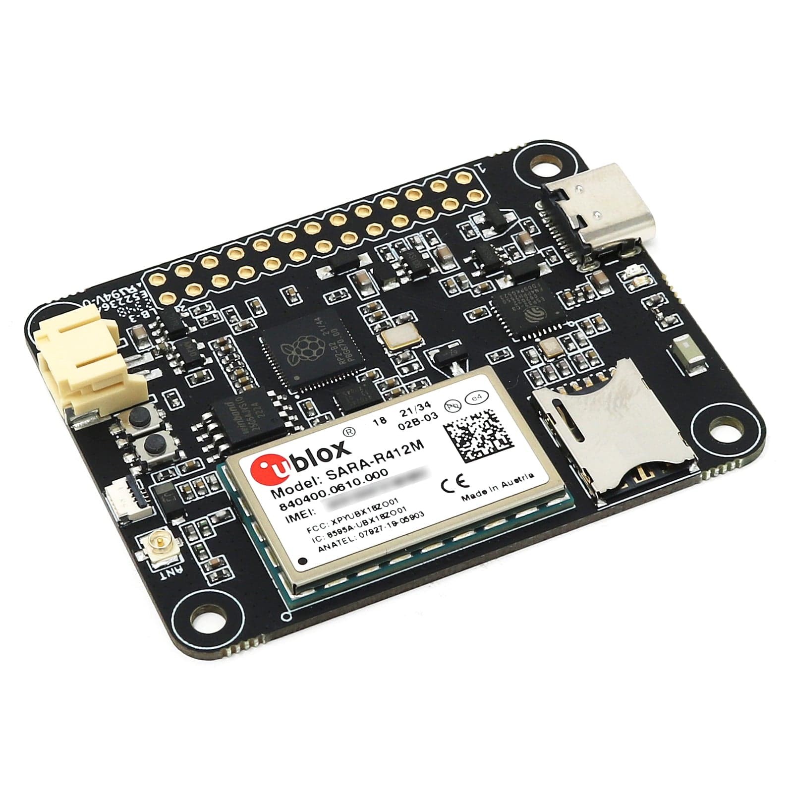
Again we have used the popular RP2040 from the Raspberry Pi Pico. An extremely well suited embedded processor for doing cool projects and managing high end communication devices such as the embedded modem.
With its dual core Cortex M0 at 133MHz, 8 MByte of FLASH and 264 Kbyte of integrated RAM it will take a very long time before you run out of resources.
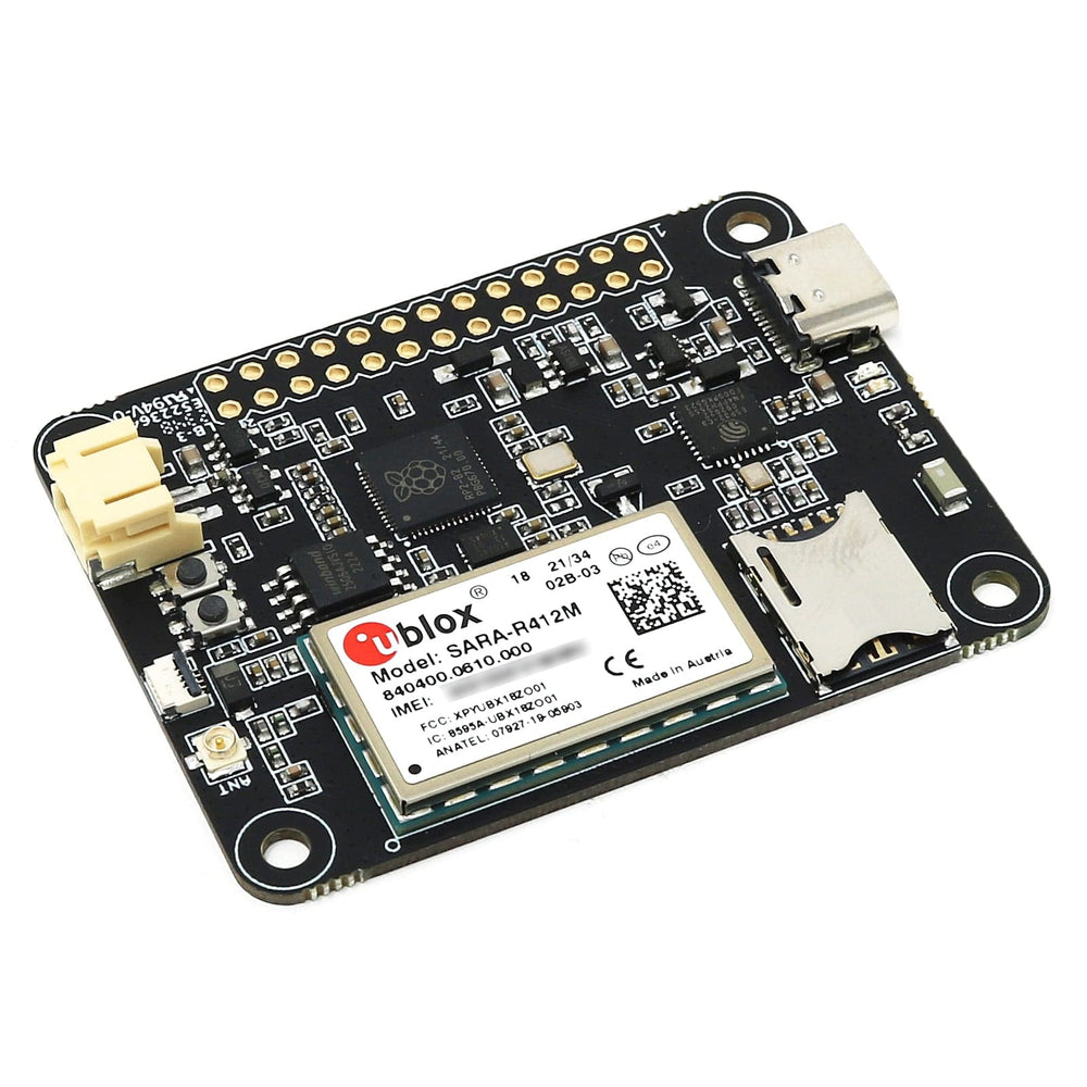
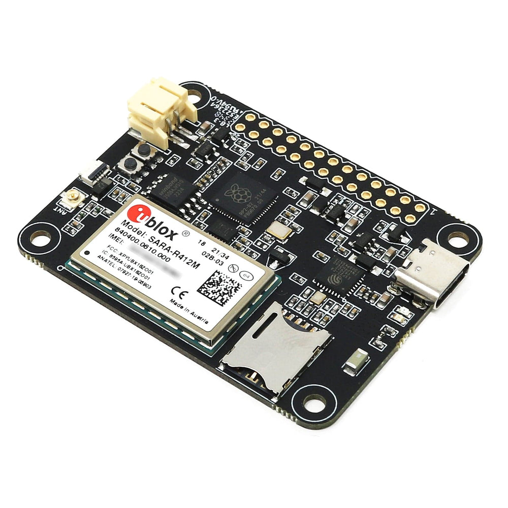
The module we selected to handle the cellular communication is the SARA-R412M series module. This module can be software multi-band configured, enabling international multi-regional coverage in both GSM as well as LTE-M/NB-IoT radio access technologies.
The SARA-R412M module is ideal for mission critical IoT solutions, as it includes a unique and immutable root of trust. It supports IoT security as a service and provides the foundation for a trusted set of advanced security functionalities. The scalable, pre-shared key management system offers data encryption and decryption, both on-device as well as from device to cloud. Utilizing the latest (D)TLS stack and cipher suites with hardware based crypto acceleration provides robust, efficient and protected communication.
Communication with the modem device is done over one of the hardware serial ports of the RP2040 and the board is configured for hardware flow control which allows you to use high data transfer speeds to and from the modem.
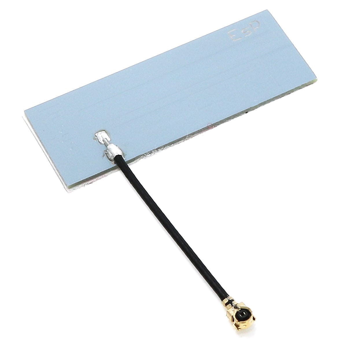
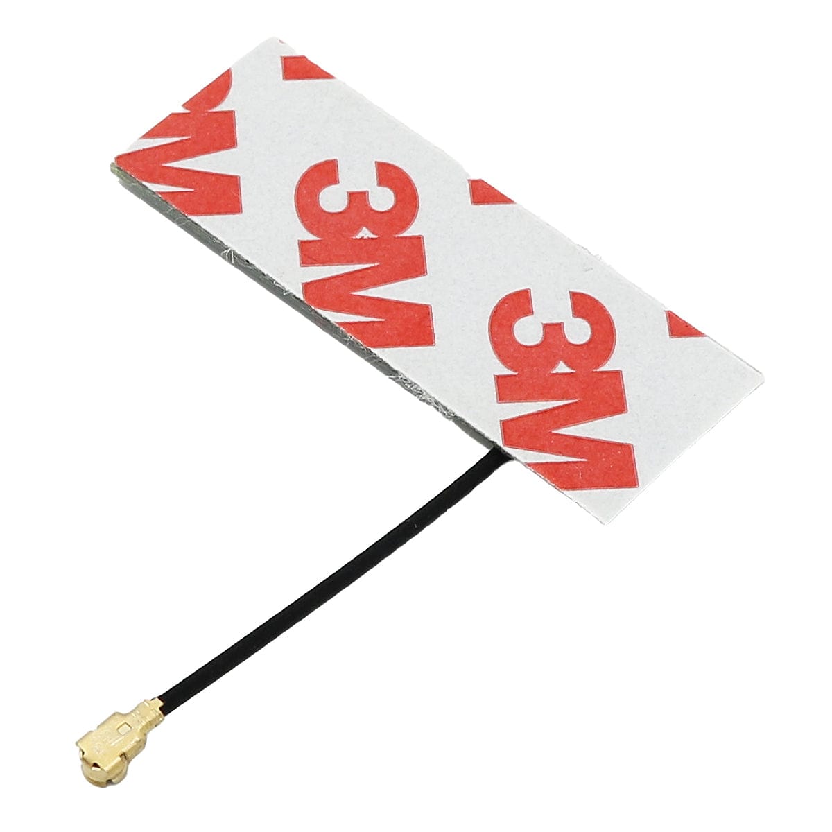
The supplied cellular antenna is connected to the board through a U.FL connector at the rear of the board. The antenna can then be attached to a plastic enclosure by peeling of the protective film and pressing it in place.
The board needs a nano SIM card in order to be able to connect to an LTE network and transfer data.
The RP2040 Connectivity board is equipped with a powerful combined single chip solution that provides the WiFi and BLE connectivity of this board. The chip we are using is the ESP32-C3FN4 from Espressif and it is a complete WiFi subsystem that complies with IEEE 802.11b/g/n protocol and supports Station mode, SoftAP mode, SoftAP + Station mode, and promiscuous mode. It also implements A Bluetooth LE subsystem that supports features of Bluetooth 5 and Bluetooth mesh.
This solution is based on an RISC-V micro controller core and comes with 4MByte of internal flash and 408Kbyte of internal SRAM as well as the advanced 2.4GHz radio.
The ESP32-C3 device comes pre loaded with the ESP-AT interpreter already programmed into flash. This interpreter provides the system with everything from low level TCP/UDP functionality up to high level functions such as a on board integrated web server, MQTT server and client functions and much more.
From the get go the on board ESP32 delivers the following functionalities:
Setting an MQTT client up for instance is a matter of three lines of code, couldn’t be easier to use.
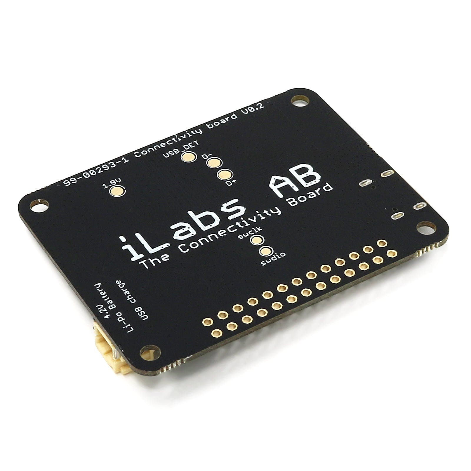
The board is equipped with a on board chip antenna for the WiFi/BLE radio and for the GSM/LTE part we have included a U.FL. connector that allows the user to hook up the antenna of their choice.
We’ve also included a antenna detection circuit on the board which together with the appropriate antenna can detect whether an antenna is attached or not (requires special circuitry on the antenna).
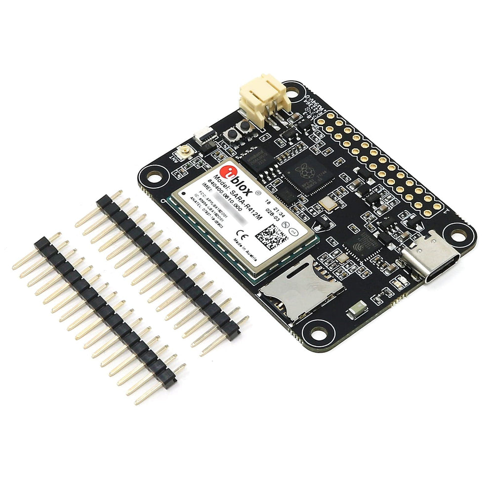
We have equipped the board with a 26 pin expansion header that allow the board to connect a multitude of sensors, buttons, displays… well basically anything you need. Here’s a list of the connector pins and their functions.
| Function | Pin | Pin | Function |
| GND | 1 | 2 | D2 |
| D1 | 3 | 4 | D3 |
| D0 | 5 | 6 | D18 |
| SDI | 7 | 8 | D11 |
| SS | 9 | 10 | D10 |
| SCK | 11 | 12 | D9 |
| SDO | 13 | 14 | D8 |
| GND | 15 | 16 | GND |
| A3 | 17 | 18 | 3.3V |
| A2 | 19 | 20 | VUSB (+5V) |
| A1 | 21 | 22 | VBAT |
| A0 | 23 | 24 | RESET (Active low) |
| AREF | 25 | 26 | EN (Pull low to deactivate module) |
There are two buttons on the board. The button closest to the USB connector is the reset button. Use it whenever you need to reset the unit. It has exactly the same functionality as the RESET pin.
Then there is the BOOT button just next to the reset button. This button must be used in conjunction with the reset button to reset the RP2040 into UF2 mode. Press the BOOT button, then the RESET button for a short moment. Then release the RESET button (while still pressing the BOOT button) and shortly after that release the BOOT button. This will place the board in UF2 mode and show up in the computer as a mass storage device.
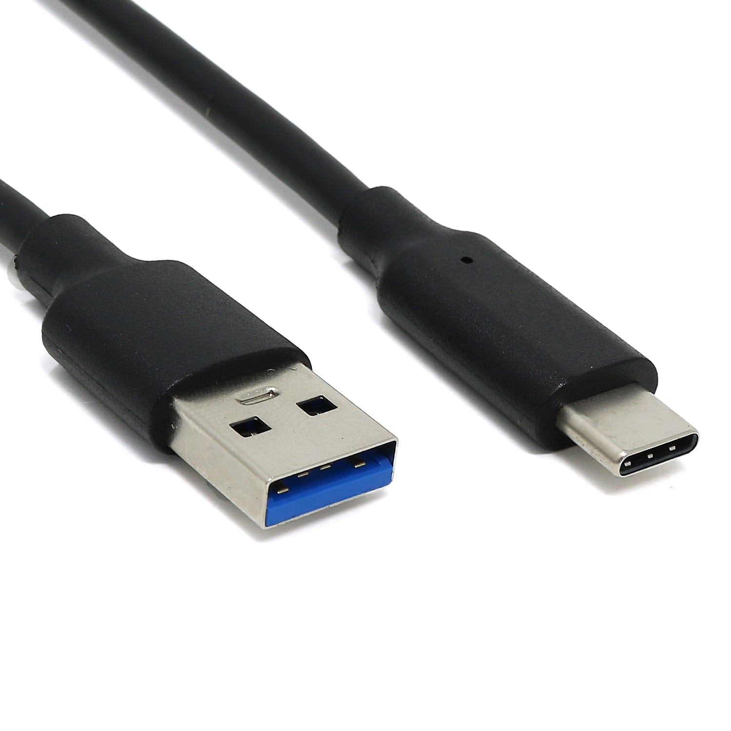
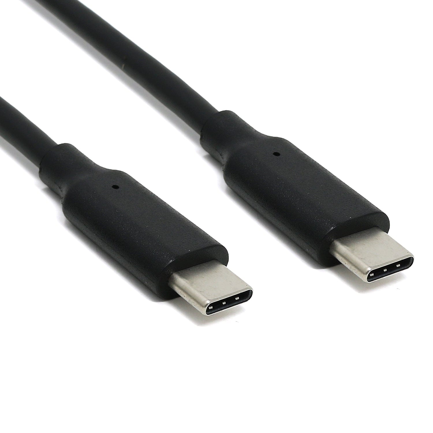
In the recent years we have noticed that we are seeing more and more USB Type C cable laying around the lab due to the fact that all new phones and accessories use them. As of yet we haven’t seen any shortage of micro USB cables but we are not getting any new ones any more and old ones do break occasionally. So we decided to go for a USB Type C connector for this board. A bonus of this is that they are quite bit more durable and you don’t have to fiddle with the cable before plugging it in.
The “RP2040 Connectivity Board” is a testament to the convergence of technology and innovation in the IoT space. Offering unmatched processing power and a suite of connectivity options, this board is your go-to solution for IoT projects demanding versatility, reliability, and ease of use. Elevate your IoT projects to new heights with the RP2040 Connectivity Board – your all-in-one solution for modern IoT challenges.
We’ve teamed up with Earle F. Philhower over at his Github page to provide Arduino support for our RP2040 based boards. You can follow the instructions on Earle’s GitHub page or you can check out our instructions here on how to install the package.
USB cable not included
Your payment information is processed securely. We do not store credit card details nor have access to your credit card information.