Hall Current Sensor DAQ HAT for Raspberry Pi
Price:
Sale price
£91.20
Stock:
Quantity:
Login / Signup
Cart
Your cart is empty


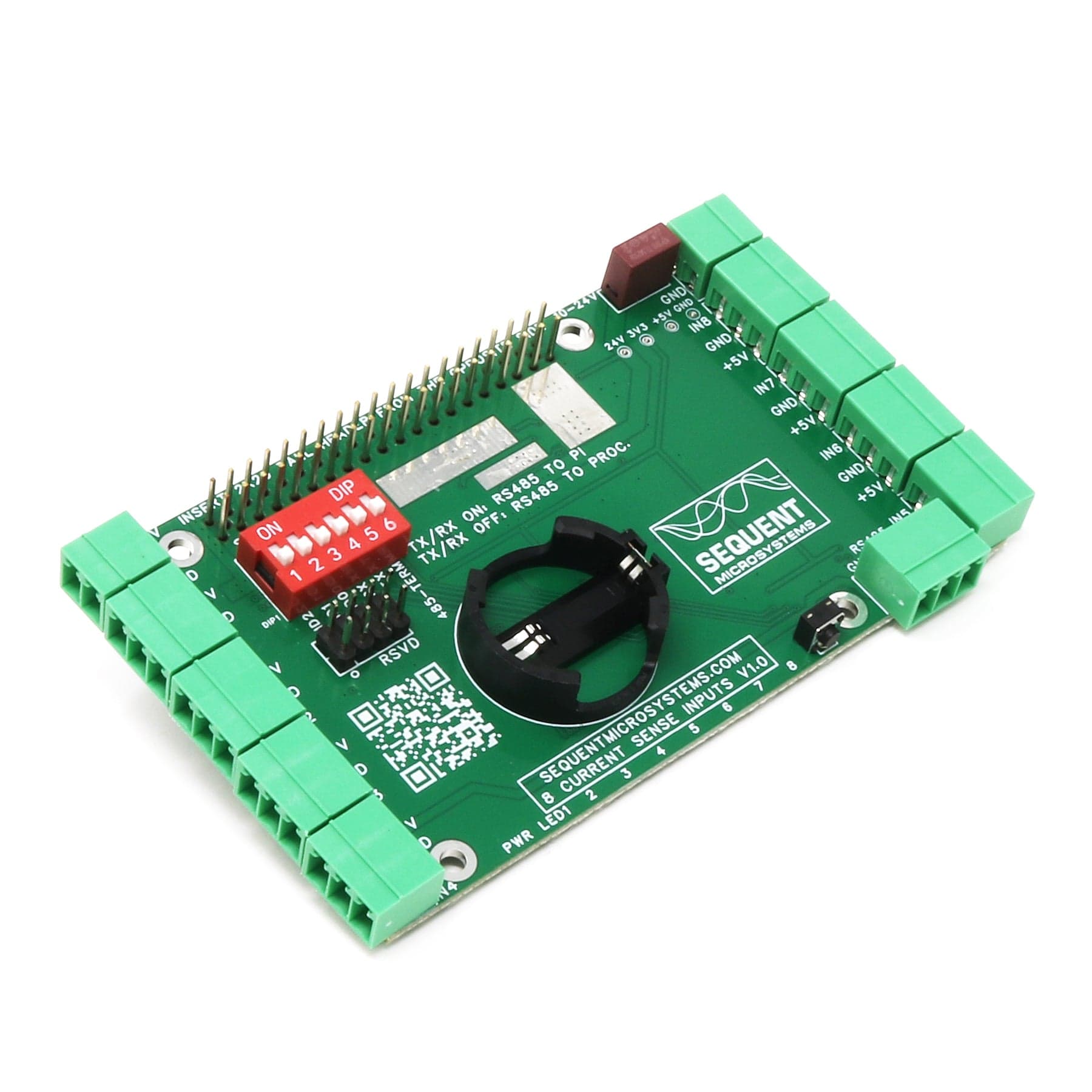
Eight Hall Current Sensor Data Acquisition HAT for Raspberry Pi - 1A to 300A Range, AC/DC🤘, RMS, RS485/MODBUS, RTC and Watchdog.
This HAT brings to Raspberry Pi eight channel data acquisition from hall current sensors. Each input signal is processed with rail to rail instrumentation amplifiers with 30µV offset, 20pA bias and 0.01µV/°C drift.
Can be used with hall sensors from 1A to 300A, AC or DC, with 2.5±0.625V or 2.5V±1V outputs. Eight LEDs can be programmed to trigger at a pre-set level of the analog inputs. The Real Time clock will keep the time almost indefinitely during power failure using a CR2032 battery backup (battery not included).
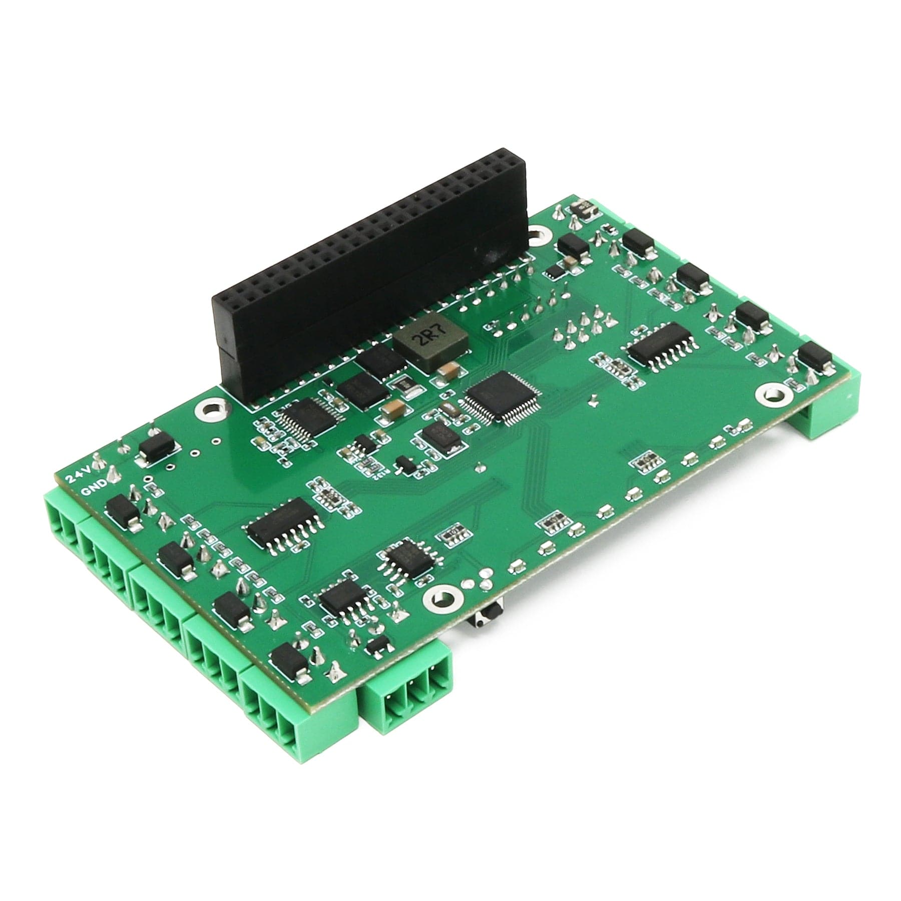
The hardware watchdog will monitor and power cycle the Raspberry Pi in case of software lockup. TVS diodes on all inputs protect the card for external ESD, and the on-board resettable fuse protects is from accidental shorts.
Raspberry Pi not included
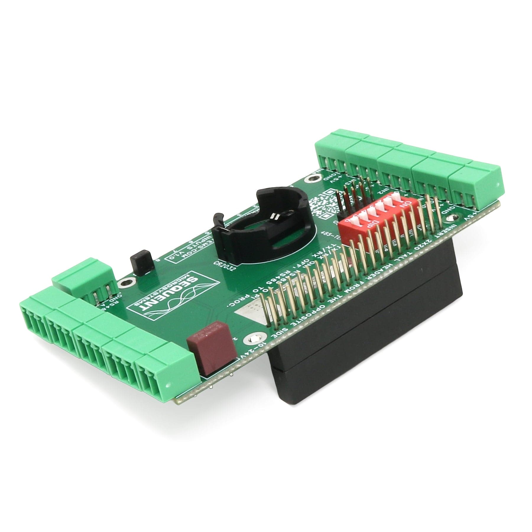
Connect the HALL Current Sensor HAT to other Industrial Automation systems using RS485/Modbus communication ports. The RS485 can be driven either from the local processor implementing Modbus RTU device, or directly from the Raspberry Pi using the dedicated pins on the GPIO connector, which are routed to the RS485 driver. In and out connectors simplify daisy-chain wiring to other devices.
The HALL Current Sensor DAQ HAT share the I2C bus using only two of the Raspberry Pi’s GPIO pins to manage all eight cards. This feature leaves the remaining 24 GPIOs available for the user. The card is compatible with all Raspberry Pi versions from Pi Zero to Raspberry Pi 5.
The HALL Current Sensor DAQ HAT operates either with a 5V/5A, or 24V/1V external power supply. The HAT supplies 5V and up to 5A to Raspberry Pi on the GPIO bus. A local 3.3V regulator powers the rest of the circuitry. The card needs only 50mA to operate.
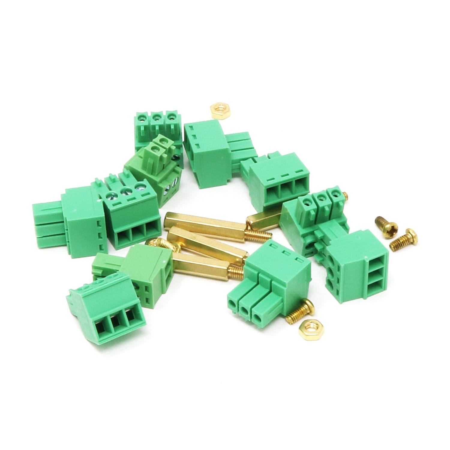
All the IO's are connected to heavy duty (8A), 3.5mm pitch pluggable connectors which make field wiring very convenient for installation and debugging.
Up to eight HALL Current Sensor Cards can be stacked on your Raspberry Pi. Three positions of the configuration DIP Switch labelled ID0, ID1, ID2 are used to select the stack level. Cards can be stacked in any order.
You can write your own application using the Command Line or Python Libraries. No programming is required if you use the Node-Red nodes provided. You can drag-and-drop the functional blocks to design your application. Examples are provided at GitHub.
All the analog inputs are calibrated at the factory, but firmware commands permit the user to re-calibrate the board, or to calibrate it to better precision. All inputs can be calibrated in two points; select the two points as close as possible to the two ends of scale. To calibrate the inputs, the user must provide analog signals. (Example: to calibrate 0-10V inputs, the user must provide a 10V adjustable power supply). Calibration process can be done using the command line interface provided.
The card contains a built-in hardware watchdog, which will guarantee that your mission-critical project will recover and continue running even if Raspberry Pi software hangs up. After power up, the watchdog is disabled, and becomes active after it receives the first reset or first period set.
The default timeout is 120 seconds. Once activated, if it does not receive a subsequent reset from Raspberry Pi within 2 minutes, the watchdog cuts the power and restores it after 10 seconds.
Raspberry Pi needs to issue a reset command on the I2C port before the timer on the watchdog expires. The timer period after power up and the active timer period can be set from the command line. The number of resets is stored in flash and can be accessed or cleared from the command line. All the watchdog commands are described by the online help function.
The Sixteen Analog-Digital Inputs card contains a standard RS485 transceiver, which can be accessed by the local processor or by Raspberry Pi. The desired configuration is set from three bypass DIP-switches marked TX and RX.
If DIP-switches are ON, Raspberry Pi can communicate with any device with an RS485 interface. In this configuration, the card is a passive bridge which implements only the hardware levels required by the RS485 protocol. To use this configuration, you need to tell the local processor to release control of the RS485 bus:
~$ 16univin [0] cfg485wr 0 0 0 0 0
If DIP-Switches are OFF, the card can operate as MODBUS slave and implements the MODBUS RTU protocol. Any MODBUS master can access all the card's inputs, and set all the outputs using standard MODBUS commands. A detailed list of commands implemented and parameters addresses can be found on GitHub:
In both configurations, the local processor needs to be programmed to release (DIP-switches ON) or control (DIP-switches OFF) the RS485 signals. See the command line online help for further information.
The card firmware can be updated in the field by running a command. The update is made with the latest firmware version located on our servers. More instructions about the process can be found on GitHub. Please make sure there is no process, like Node-Red or Python scripts, that tries to access the card during the update process.
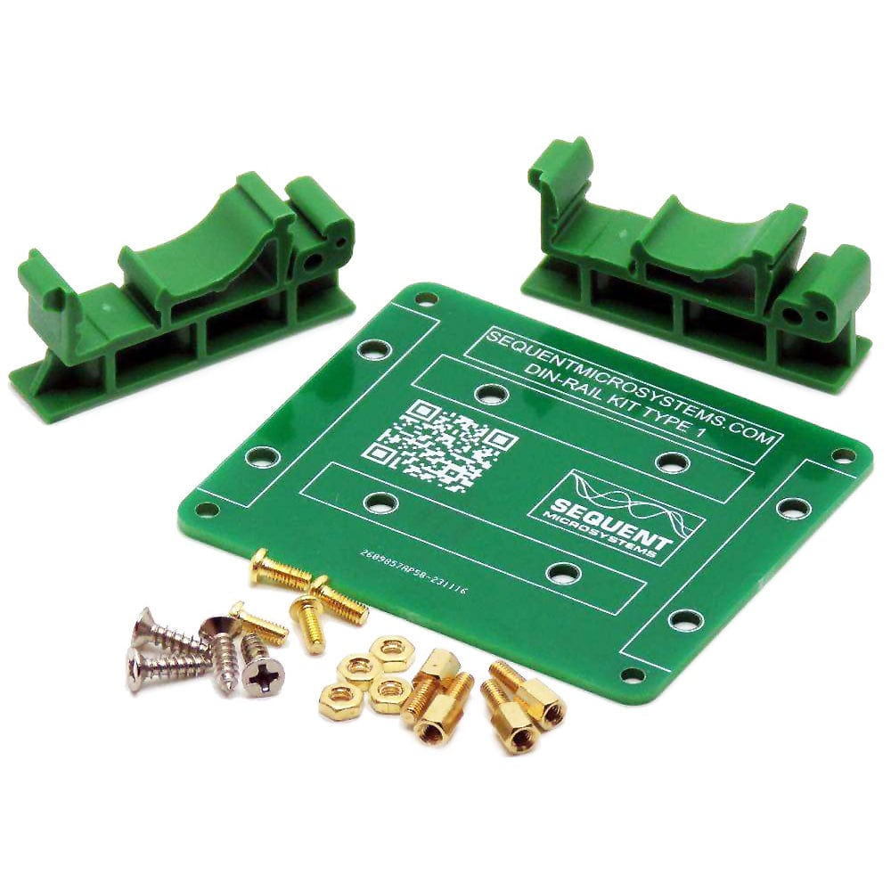
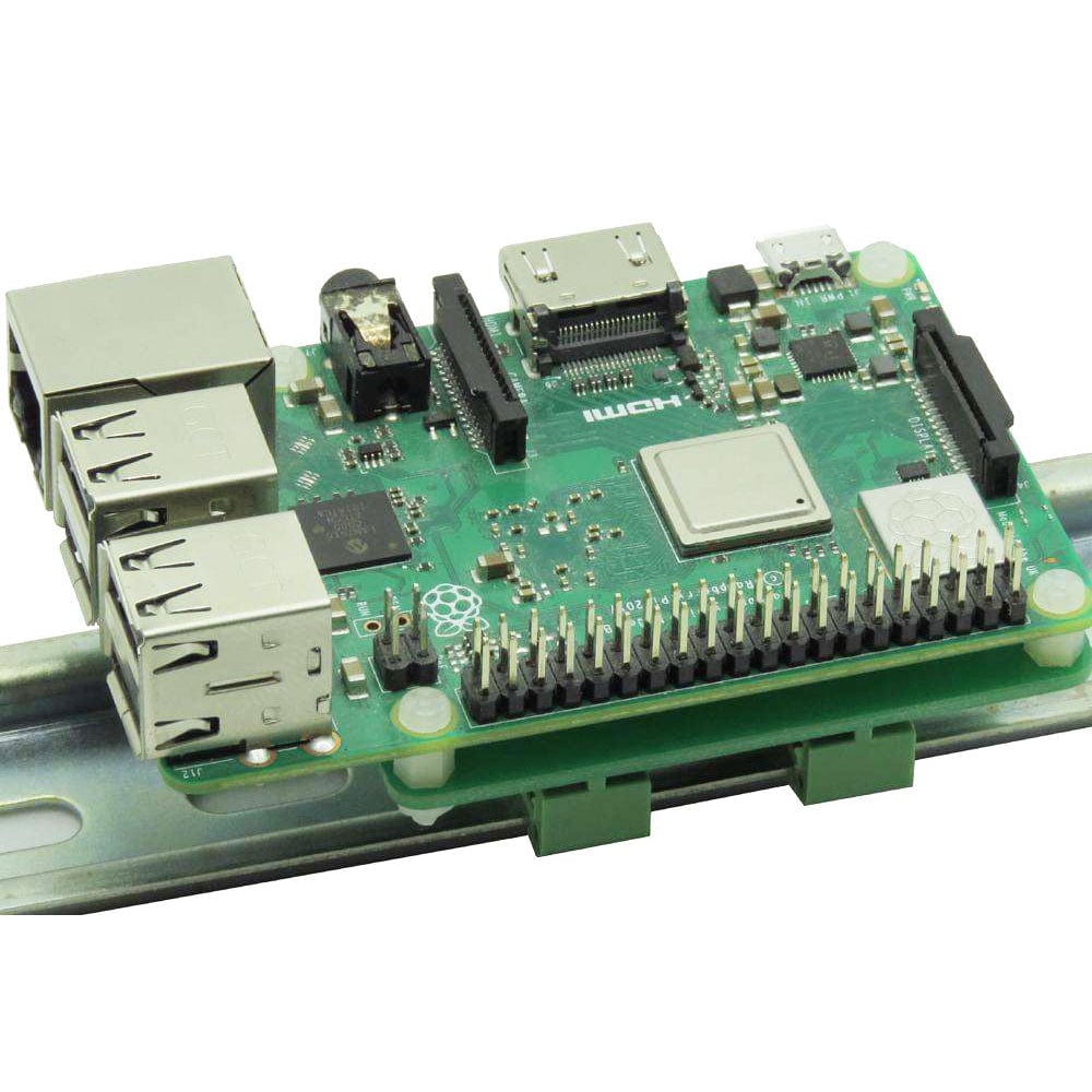
The card can be installed parallel on a DIN-Rail using the DIN-Rail Kit Type 1, or perpendicular using the DIN-Rail Kit Type 2.
Raspberry Pi not included
Your payment information is processed securely. We do not store credit card details nor have access to your credit card information.