Four Smart Relays with Universal Inputs 8-Layer Stackable HAT for Raspberry Pi
Price:
Sale price
£72
Stock:
Login / Signup
Cart
Your cart is empty


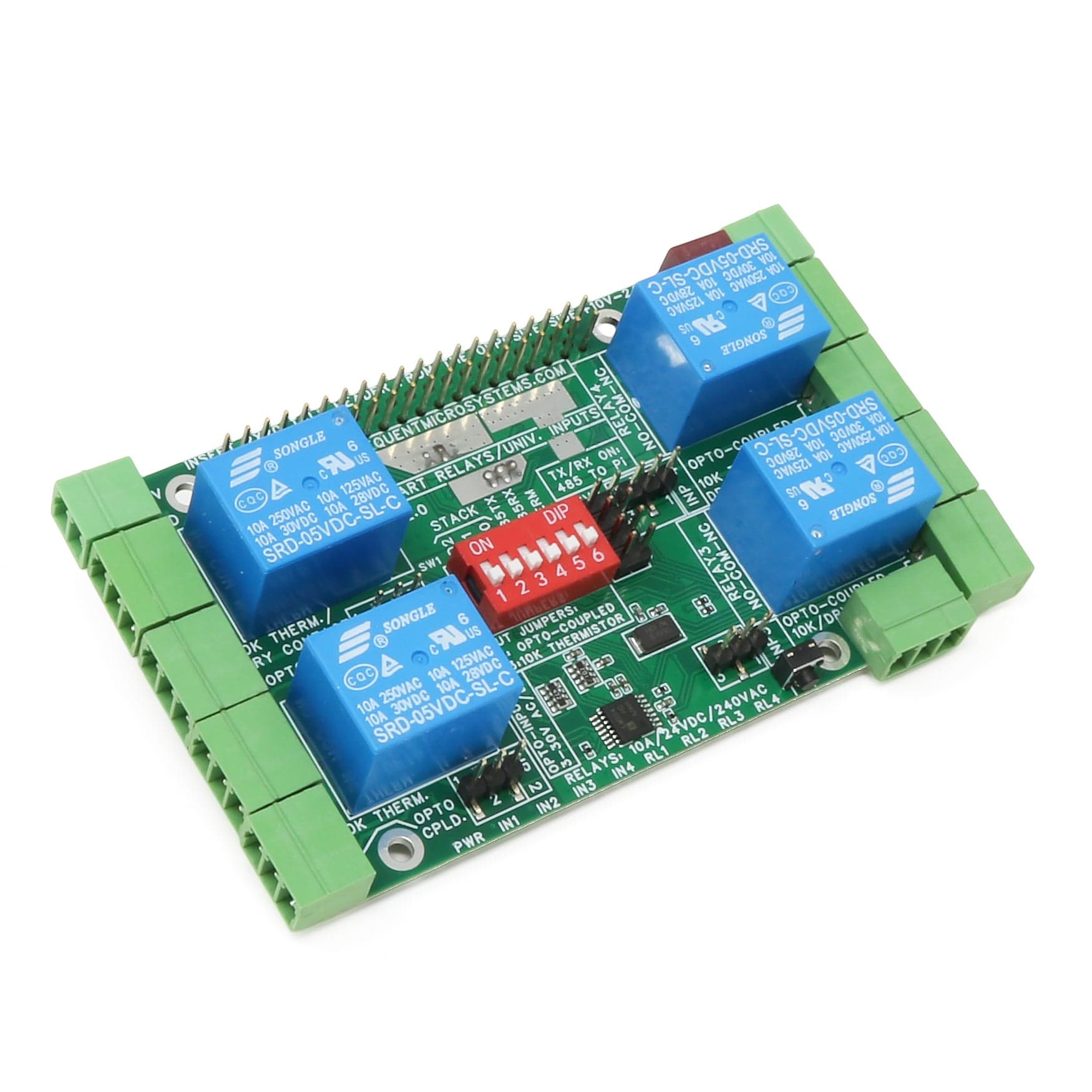
The Sequent Smart Relays HAT for Raspberry Pi features four relays with HALL sensors, current limiting, 10A switching, universal inputs, RS485/MODBUS, PWM and encoder support, a reset button, and GPIO-friendly stacking. Includes pluggable connectors, power loss protection, and Home Assistant integration.
The Smart Relays HAT for Raspberry Pi is an ideal solution for mission-critical projects where you have to be 100% sure that your system works as expected. HALL effect sensors on relay outputs monitor the load current in real time. Not only can you be sure that your loads operate within specified parameters, but you can also measure the load power, and you can limit the load current to any value from 1 to 10A.
The HAT's universal inputs can read temperatures from 10K thermistors, dry contact or opto-isolated 0-24V signals. Stackable to 8 layers, the Smart Relays HAT can add up to 32 relays and 32 analog/digital inputs to each Raspberry Pi in a very compact form factor.
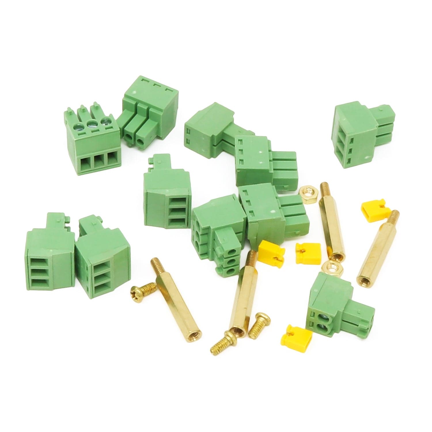
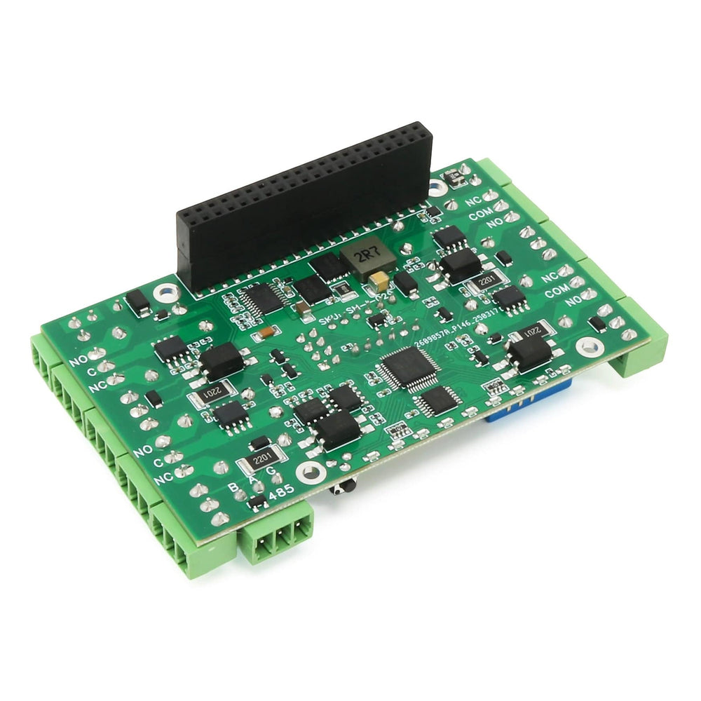
Pluggable connectors make the card easy to use when multiple cards are stacked up. All relays have Normal Open and Normal Close contacts and can switch up to 10A/240VAC.
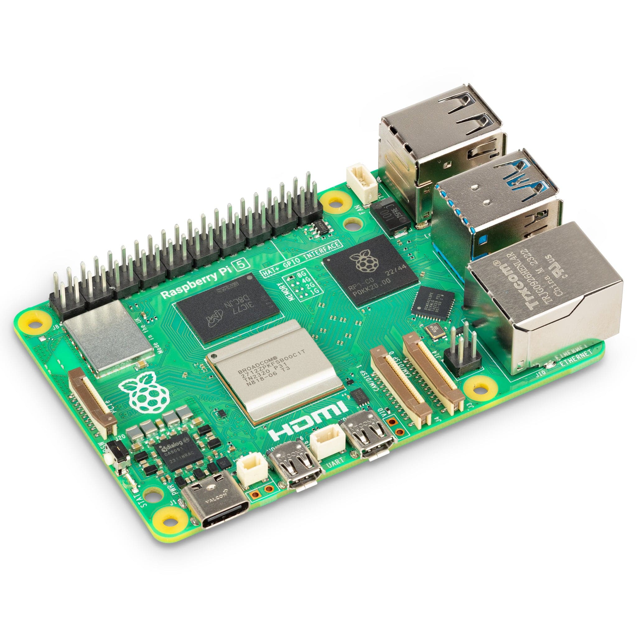
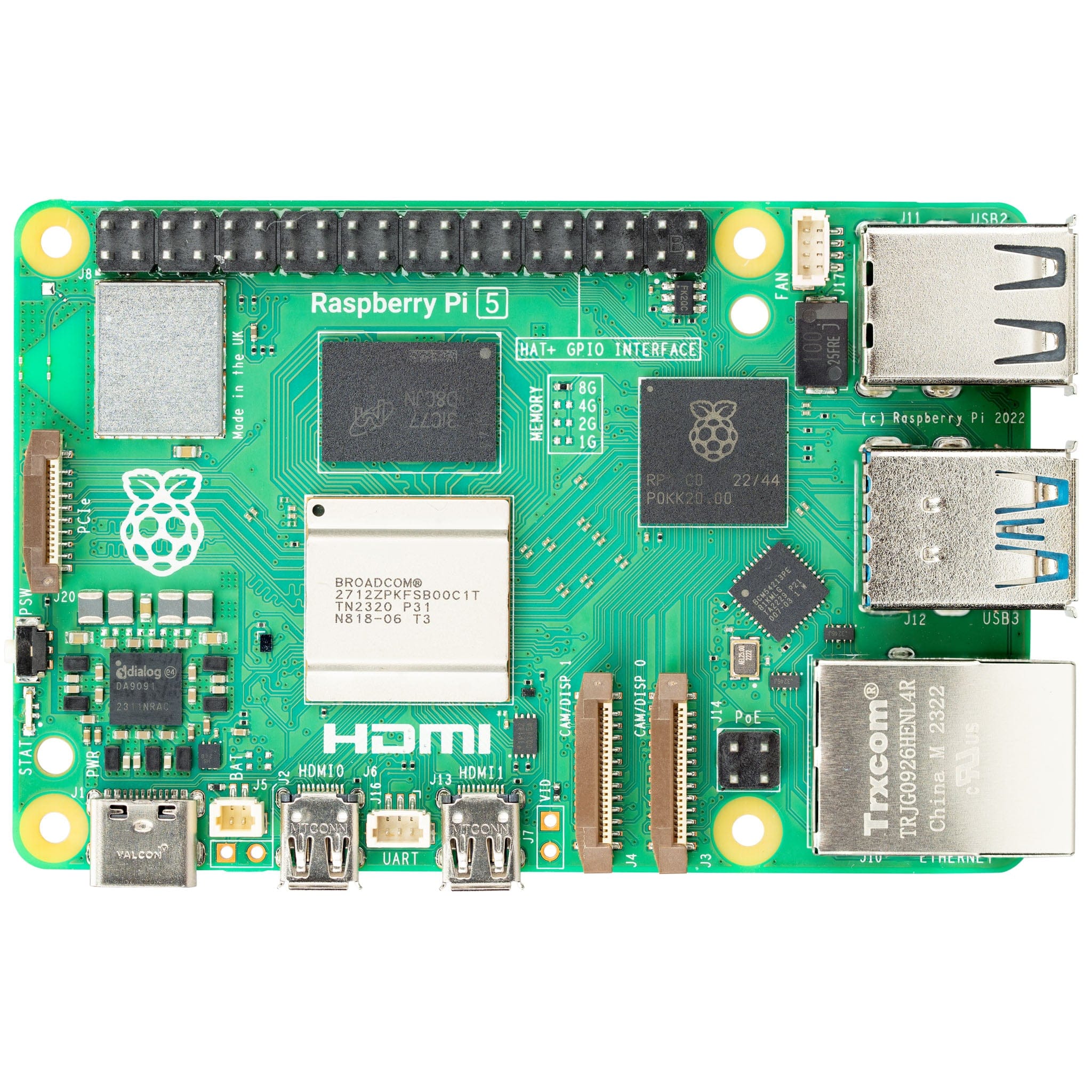
Raspberry Pi not included
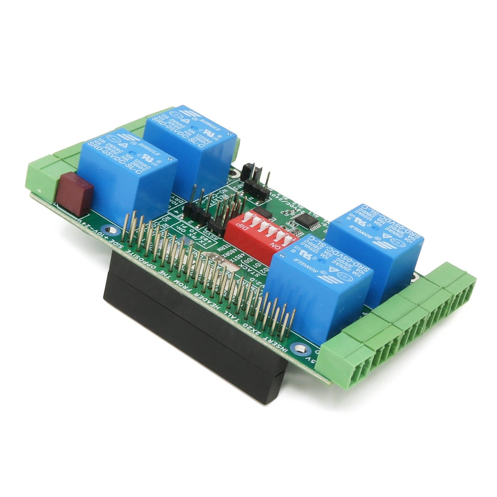
The Smart Relays card is compatible with all 40-pin Raspberry Pi models from Zero to Pi 5. All stacked cards share the I2C bus using only two of the Raspberry Pi’s GPIO pins to manage all eight cards. This feature leaves the remaining 24 GPIOs available for the user.
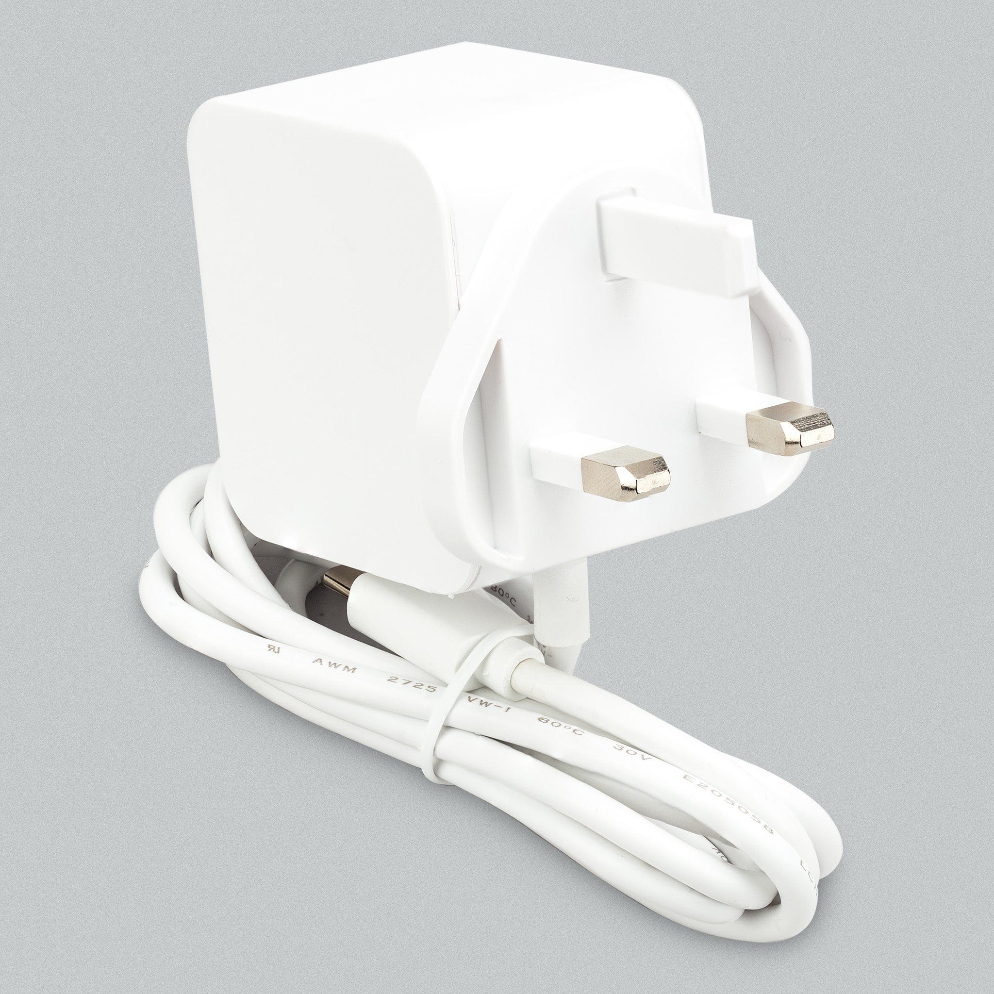
The card operates from a 5V or 10-24V power supply. In both cases, it provides 5V and up to 5A to the Raspberry Pi. The relay coils are also powered from 5V. The card draws less than 50mA with all relays off. Each relay needs about 80 mA to turn on.
Up to eight cards can be stacked on your Raspberry Pi. Three positions of the configuration DIP switch labelled ID0, ID1, ID2 are used to select the stack level. Cards can be stacked in any order.
Shutting down the Raspberry Pi by turning off the power can result in MicroSD card failure. To prevent this, a shutdown command needs to be used before power cut-off. But this requires a monitor, keyboard and mouse connected to the Pi.
A momentary on push button installed at the edge of the board provides a convenient way to shut down the Raspberry Pi. The button is read by the local processor, which can be programmed to signal the Raspberry Pi by setting low pin 37 of the Raspberry Pi GPIO connector (GPIO26). You can also read the status of the pushbutton from the I2C interface. You need to write a script which monitors this pin, and if pressed for more than a desired time, issues the shut-down command.
The card can be tested before installation by running a simple command from the command line. The card will cycle each relay on and off at 0.5 second intervals. The clacking noise of the relays and the lighting of the LEDs will assure that all relays are functioning.
A standard RS-485 transceiver permits the Raspberry Pi to communicate using any protocol including MODBUS, PROFIBUS, camera PTZ control, etc. The transceiver can be driven either from the Raspberry Pi serial port, or directly from the local processor. Install the jumpers 485-TX and 485-RX on connector J3 to drive the port from Raspberry Pi. Install the terminator jumper 485-TERM if the card is last on the RS-485 chain.
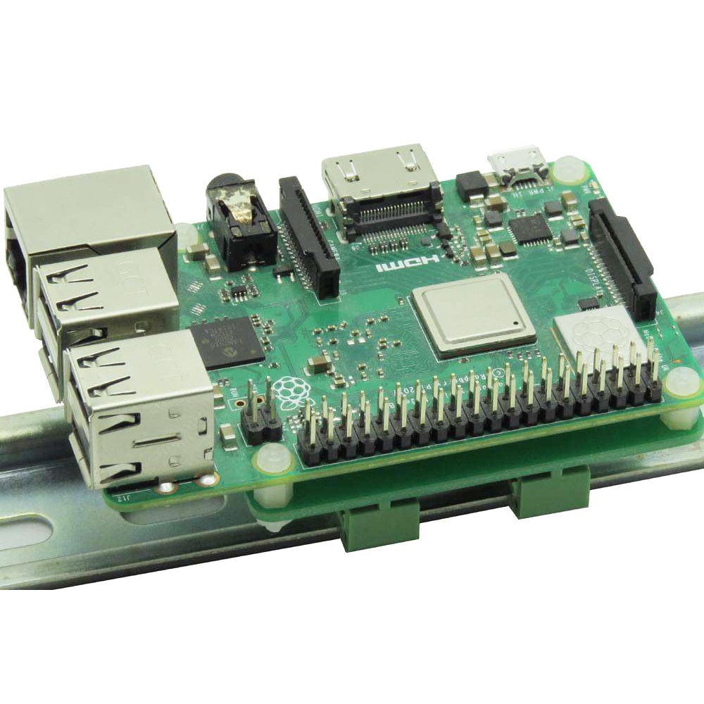
The card can be installed parallel on a DIN rail using the DIN-Rail Kit Type 1, or perpendicular using the DIN-Rail Kit Type 2.
You can write your own application using the command line or Python libraries provided. No programming is required if you use the Node-Red nodes we supply. You can drag-and-drop the functional blocks to design your application. Examples are also provided.
Raspberry Pi not included
Your payment information is processed securely. We do not store credit card details nor have access to your credit card information.