Challenger RP2040 WiFi/BLE MkII (Chip Antenna)
Price:
Sale price
£15
Stock:
Quantity:
 Skip to content
Cart
Your cart is empty
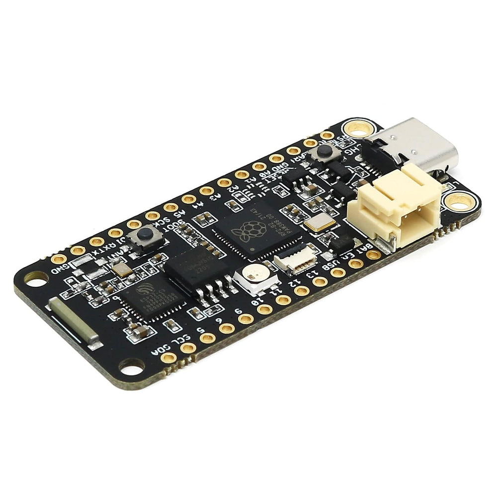
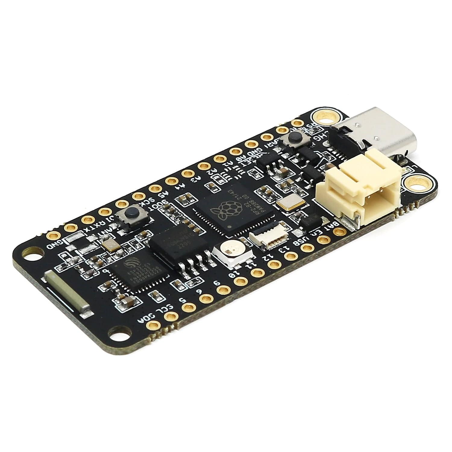
The iLabs Challenger RP2040 WiFi/BLE MkII is an Arduino/Micropython compatible Adafruit Feather format microcontroller board based on the RP2040 chip used in the Raspberry Pico, equipped with a WiFi/BLE chip that provides both WiFi as well as BLE functionality.
The MkII version is an updated version of the first iteration of the board including a new Bi2C connector. The new MkII version is fully backwards compatible with the original version which means you can use all the available software for it.
This is the chip antenna version of the Challenger RP2040 WiFi/BLE MkII - other versions are detailed below.
Please read the datasheet for detailed information on this board.
Three versions of the Challenger RP2040 WiFi/BLE MkII are available:
...or view the full range of Challenger boards here!
The RP2040 is the debut microcontroller from Raspberry Pi. It brings their signature values of high performance, low cost, and ease of use to the microcontroller space.
With a large on-chip memory, symmetric dual-core processor complex, deterministic bus fabric, and rich peripheral set augmented with our unique Programmable I/O (PIO) subsystem, RP2040 provides professional users with unrivalled power and flexibility. With detailed documentation, a polished Circuitpython port, and a UF2 boot loader in ROM, it has the lowest possible barrier to entry for beginner and hobbyist users
For more detailed information about the RP2040, click here!
The Challenger RP2040 WiFi/BLE MkII board is equipped with a powerful combined single-chip solution that provides the WiFi and BLE connectivity of this board.
The chip we are using is the ESP32-C3FN4 from Espressif and it is a complete WiFi subsystem that complies with IEEE 802.11b/g/n protocol and supports Station mode, SoftAP mode, SoftAP + Station mode, and promiscuous mode. It also implements a Bluetooth LE subsystem that supports the features of Bluetooth 5 and Bluetooth mesh.
This solution is based on a RISC-V microcontroller core and comes with 4MByte of internal flash and 408Kbyte of internal SRAM as well as the advanced 2.4GHz radio.
The ESP32-C3 device comes pre-loaded with the ESP-AT interpreter already programmed into flash. This interpreter provides the system with everything from low-level TCP/UDP functionality up to high-level functions such as an onboard integrated web server, MQTT server and client functions and much more.
From the get-go the onboard ESP32 delivers the following functionalities:
Setting an MQTT client up for instance is a matter of three lines of code, and couldn’t be easier to use.
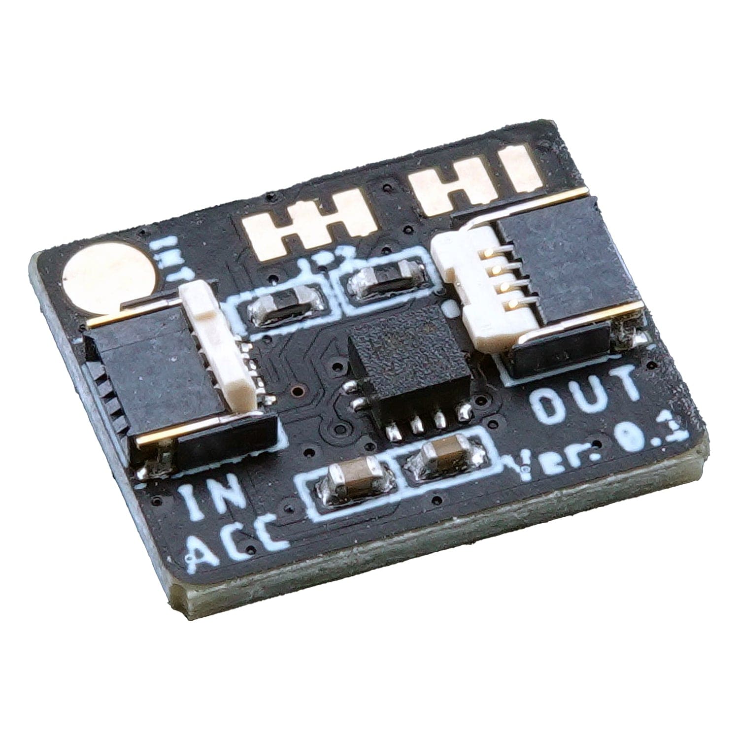
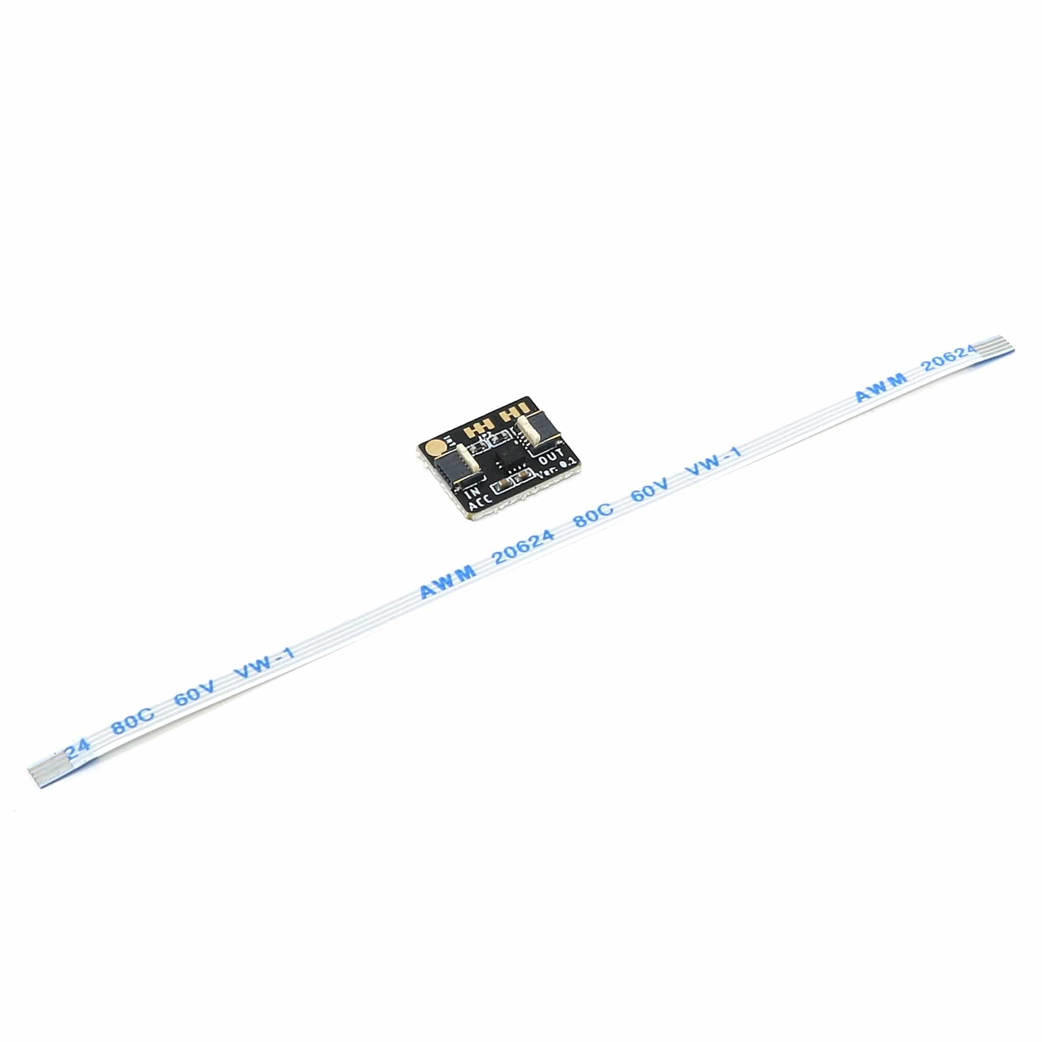
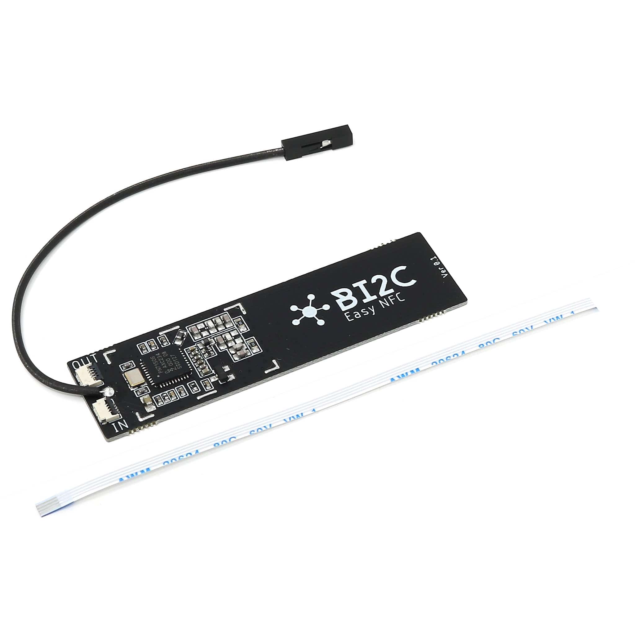
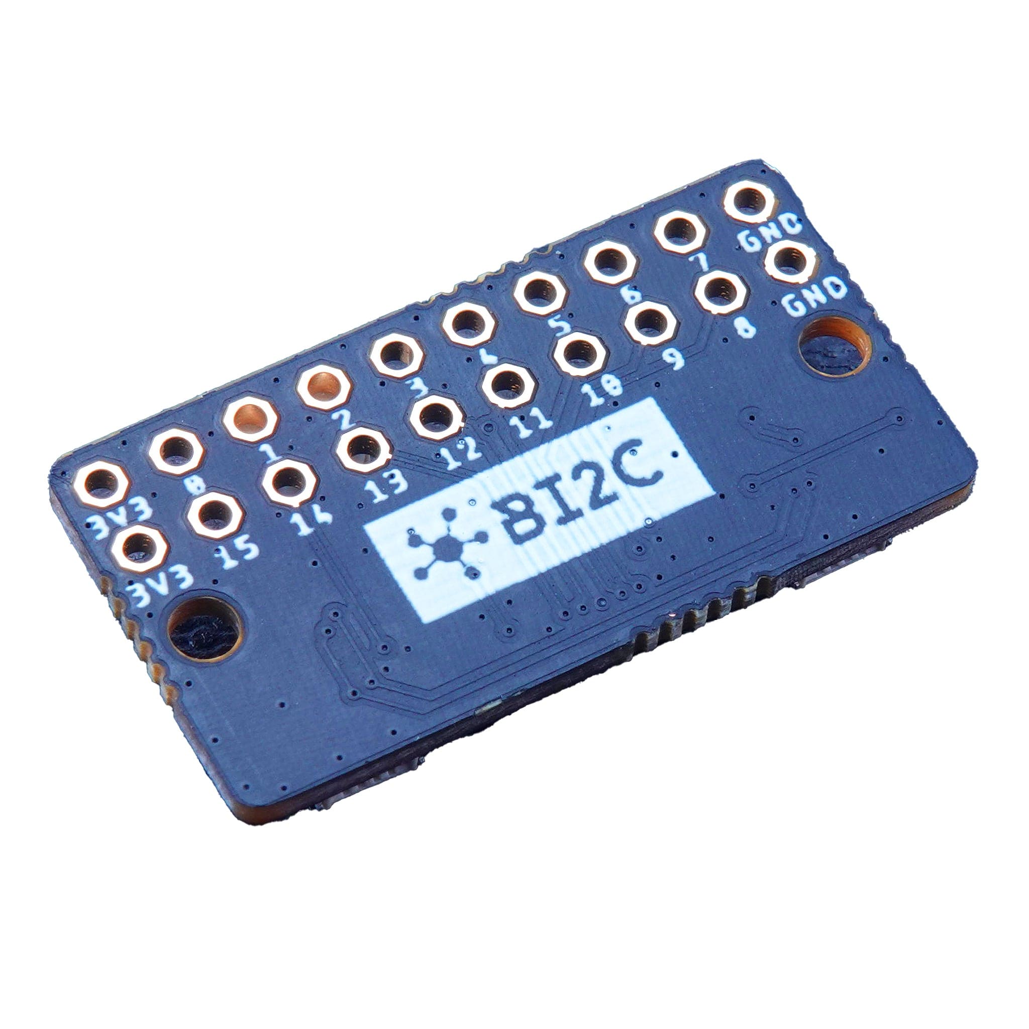
This board includes a Bi2C connector, a small FFC connection used to connect other Bi2C devices (such as the examples listed below).
The Bi2C (Bus I2C) concept is a spin-off from the existing Groove, Stemma and Qwiic ecosystems where we use an FFC (Flexible Flat Cable) instead of normal threaded cables to create the connection. This means that we can get away with connectors that have 0.5mm pitch which makes them super thin and compact. Read more about Bi2C here.
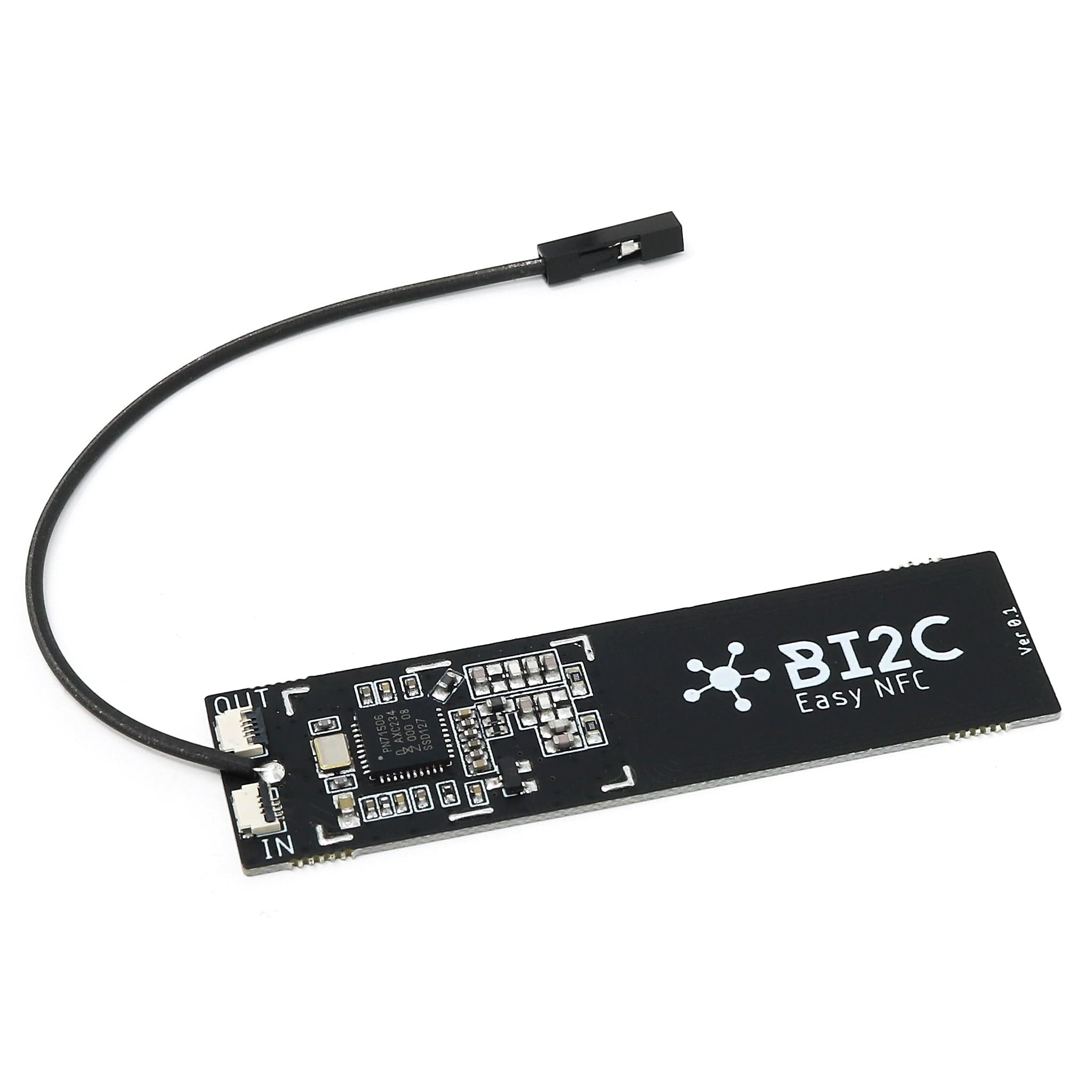
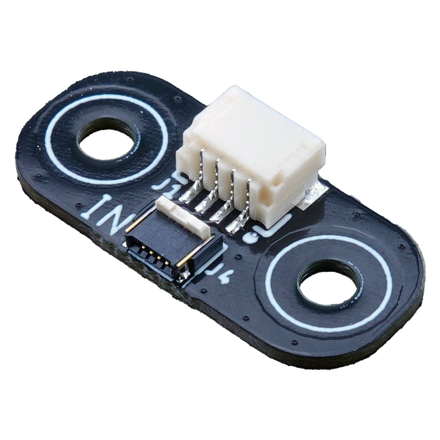
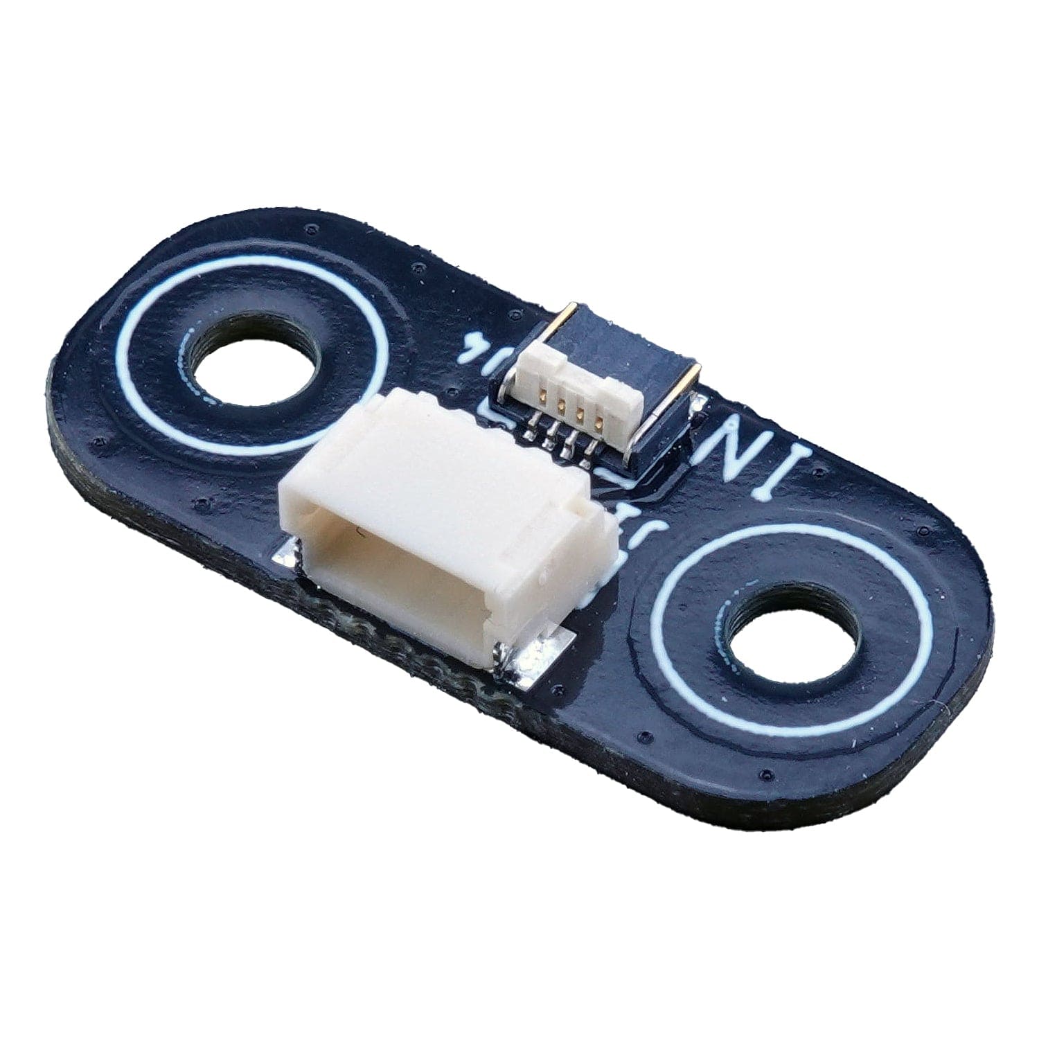
You can also use Bi2C with Qwiic/STEMMA QT boards using the Bi2C Qwiic/STEMMA QT adapter, giving you an ultra-thin cable option for compact projects and enclosures.
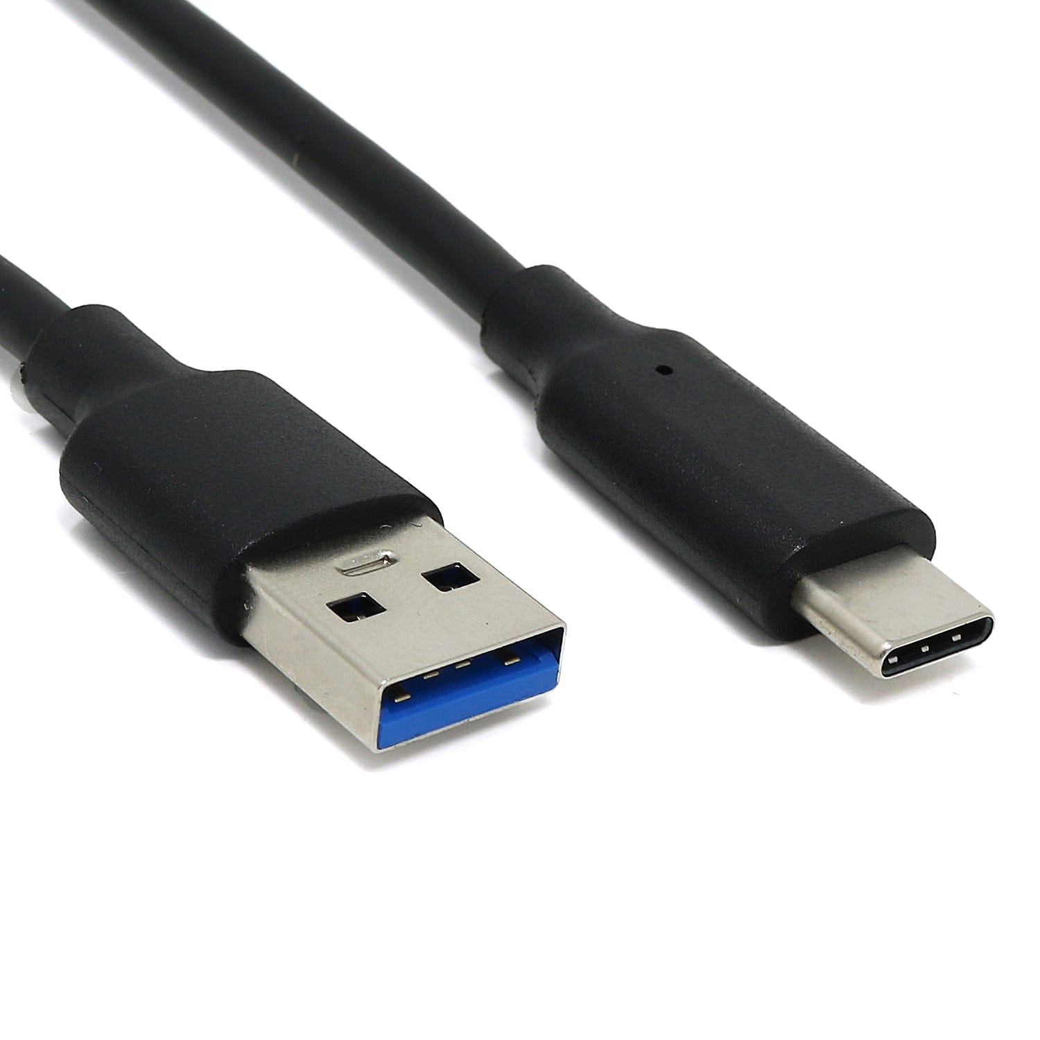
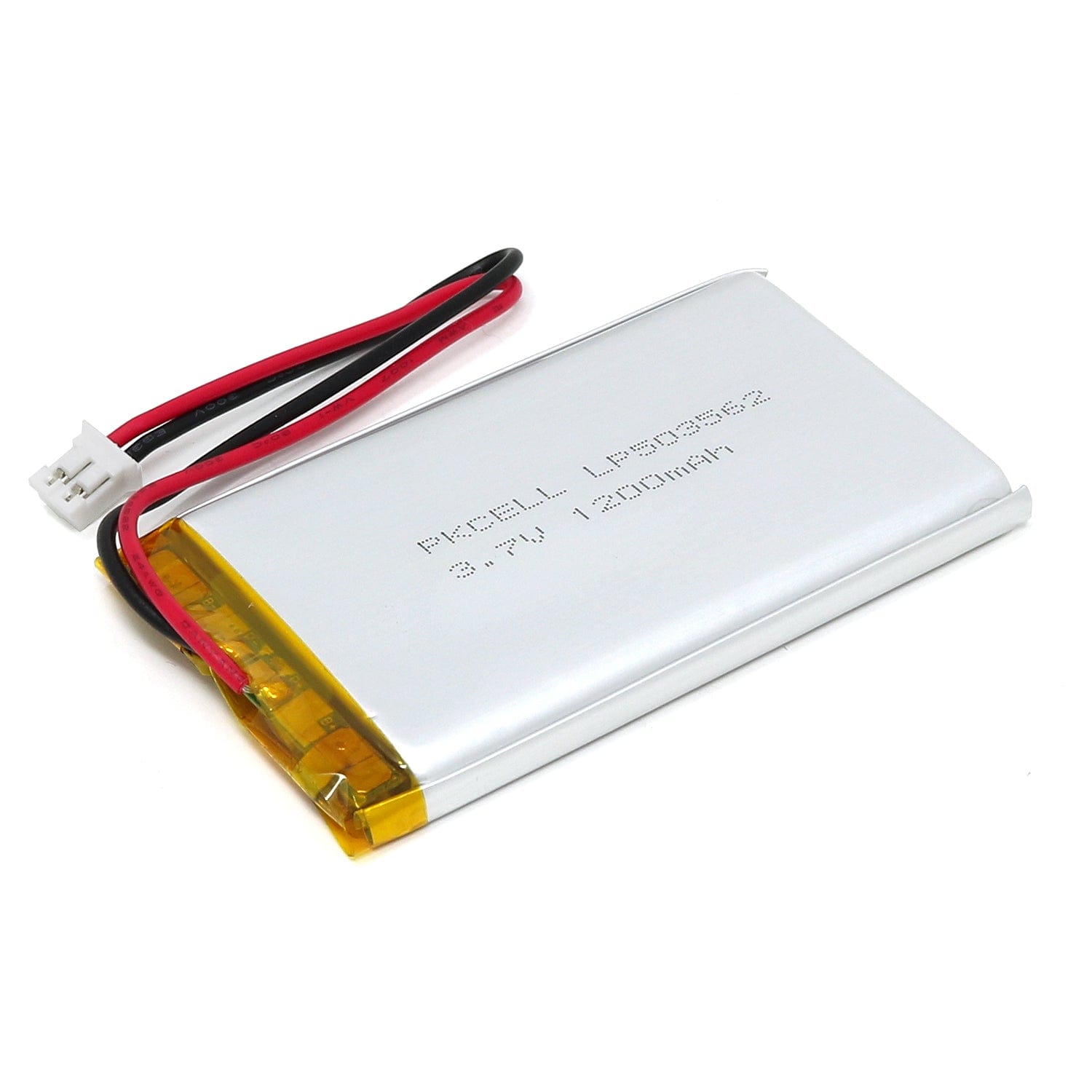
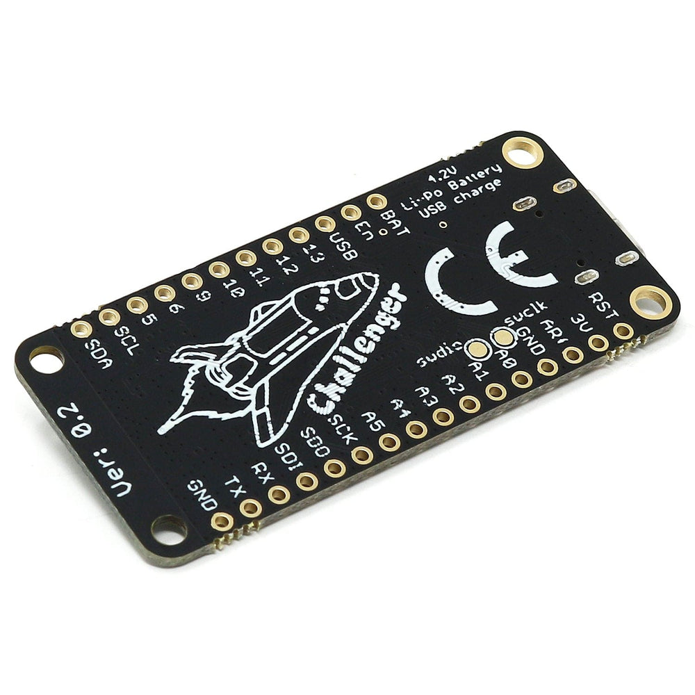
The board comes with a sturdy USB-C connector, a battery connector that allows you to plug in standard 1-cell LiPo batteries. It also has an onboard charger chip that charges the battery whenever a USB cable is connected or 5V is applied to the USB power header pin.

The Challenger is fully compatible with both the micropython package found at the Raspberry Pi site as well as Adafruit's CircuitPython. Instruction on how to install the python interpreter of your choice is available on the respective websites.
We’ve teamed up with Earle F. Philhower over at his Github page to provide Arduino support for our Raspberry Pi Pico-based boards. All instructions on how to install the board support package as well as multiple examples on how to use the Raspberry Pi Pico processor can be found there.
To simplify the hardware aspect of the WiFi modem we have included a small helper class in the Arduino IDE that is always available to you as a developer. This new class replaces the previous examples on how to do a proper reset and sync.
The first thing you need to do in your sketch is to include the HW support library and the WiFi library by entering:
#include
#include
After this, all you need to do before starting the WiFi manager is the following:
if (Challenger2040WiFi.reset())
    Serial.println(F("WiFi Chip reset OK !"));
else
    Serial.println(F("Could not reset WiFi chip !"));
After these steps the modem is initialized and is ready to accept your commands. The reset() function of the built-in Challenger2040WiFi library will perform a HW reset of the WiFi modem and wait for it to return the “ready” prompt. After this, a WiFi manager can be started and start communicating with the modem. Here at iLabs we use the WiFiEspAT library and initializing the stack is as easy as:
WiFi.init(ESP_SERIAL);
Make sure the library is included at the top of the file with: #include <WiFiEspAT.h>
At this point, you can also do a check to make sure that the data link is set up properly:
if (WiFi.status() == WL_NO_MODULE) {
    Serial.println("Communication with WiFi module failed!");
    // don't continue
    while (true);
}
You are now good to go, so doing something like this will work as expected:
Serial.println("Waiting for connection to WiFi");
while (WiFi.status() != WL_CONNECTED) {
    delay(1000);
    Serial.print('.');
}
Serial.println();
Serial.println("Connected to WiFi network.");
The default baudrate between the RP2040 micro controller and the ESP8285 WiFi modem is 115200 and while this is probably good for most IoT applications that normally don’t send very much data it can sometimes be useful to increase the baudrate. The Challenger2040WiFi contains a method for doing this and again it is super simple to use. Just do the following and the baud rate will be altered on both systems and the devices will be synced up.
After this you can proceed to communicate with the device as normal.
Challenger2040WiFi.changeBaudRate(921600);
After the modem has been initialzed and it has reported that it is ready you can now send a command to it. Here’s an example on how a simple command can be sent.
Serial2.println("ATE0");
This command simply tells the modem not to repeat everything back that you send to it. If you want to enable this again you would simply send the following command:
Serial2.println("ATE1");
This example Arduino program creates a USB2Serial pass through to the ESP32. This can be used to flash the ESP with new upgraded software or you can write your own code and use this short snippet to flash the device.
Your payment information is processed securely. We do not store credit card details nor have access to your credit card information.