 Skip to content

MicroPython Skill Builders - #2 LEDs & Lists
This is the second instalment of our MicroPython Skill Builders series by Tony Goodhew, aiming to improve your coding skills with MicroPython whilst introducing new components and coding techniques - using a Raspberry Pi Pico!
We continue the series today by looking at using multiple LEDs and Lists.
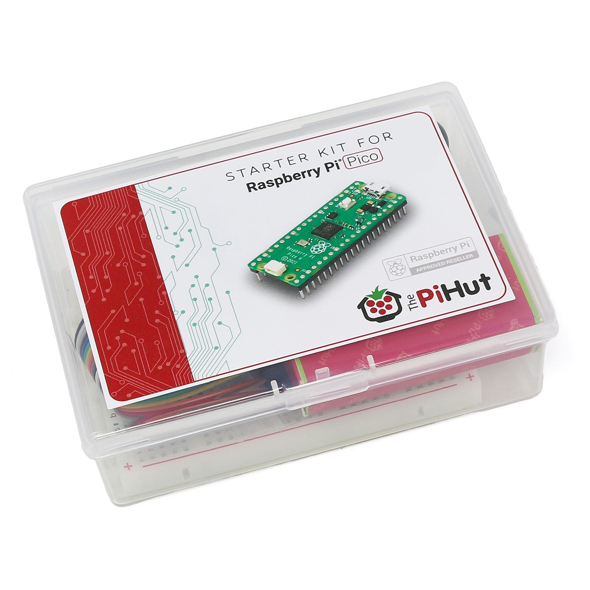
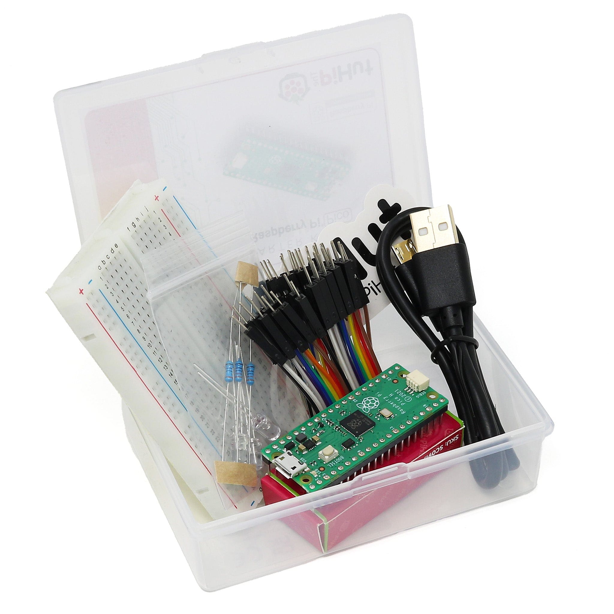
What you will need
We assume that you have installed Thonny on your computer and set up your Raspberry Pi Pico with the most recent MicroPython firmware (UF2). If not, check out our Raspberry Pi Pico Getting Started Guide where this is covered in detail.
You will need:
- Raspberry Pi Pico with header pins
- A full-size breadboard
- Micro-USB cable (for power and programming the Pico)
- A pack of male-male and male-female Jumper Wires (a mixed pack is available here)
- Tactile buttons (a mixed pack is available here)
- 10K Ohm potentiometer (we may use a few of these in future episodes)
- 10x Current limiting resistors (330 Ohms)
- 10x 5mm LEDs (a mixed pack is available here)
- OR a 10-segment light bar
- Current limiting resistors (330 Ohms)
The Circuit
We start with the breadboard circuit from the first tutorial and add two LEDs with current limiting 330 Ohm resistors on pins GP17 and GP18.
Follow the diagram below if you're constructing this circuit for the first time:

Testing the Circuit
Copy the program below, paste it into Thonny and save it as 3 LEDSv1.py
Now run the program. There are two loops in the program. The first flashes all three LEDS at the same time and the second flashes the LEDs one at a time. Pressing the button breaks the program out of a loop.
Things to notice
- The LEDs each have a different name: ledA, ledB and ledC
- The LEDs appear to switch on and off together but they are actually turned on and off in sequence. This happens so fast that we cannot see the delay
- In each loop we need a different piece of code each time we change the state of an LED or pause
Imagine how long the code in the second loop would be it we had ten LEDs instead of just the three in this circuit...
Using Lists in Micropython
There is a more efficient way of naming the LEDs which makes turning them on and off much easier to code – we use a list and then point to items in the list.
In MicroPython, a list is a structure containing several items which can accessed individually by means of a pointer or index.
Here is a simple example program using a list of friends’ names. Copy and run the program before we go through it in detail:
Once run, the output of the program should look like this:
Let’s look at the code more closely
We create a list of three names. The names, which are strings of characters, are enclosed in quotation marks, separated by commas and enclosed in square brackets. The list has the variable name, friends.
We print out the list and it appears as a single line with the brackets, quotes and commas.
The next line determines the number of items in the list using the len() function to count them. Finally, we print the number forcing a couple of new lines with the "\n" strings.
Here we use the pointer, p, to point to each item in the list and print it out.
The end=' ' at the end of the print statement prevents the normal new line being generated by the print command, and the names are listed on the same line with a single space between them. The last print generates two line feeds.
This time we move the pointer in the opposite direction and print the names in reverse order.
(n – 1) points to the last element in a list with n items; while 0 points to the first item.
This line adds a new name to the end of the friends list with the .append() method.
Here we update the variable holding the length of the list and print it.
Then we print the extended list in normal and reverse order
This line demonstrates that the index or pointer counts from zero. An index equal to 1 points to the second item in the list.
A List of LEDs
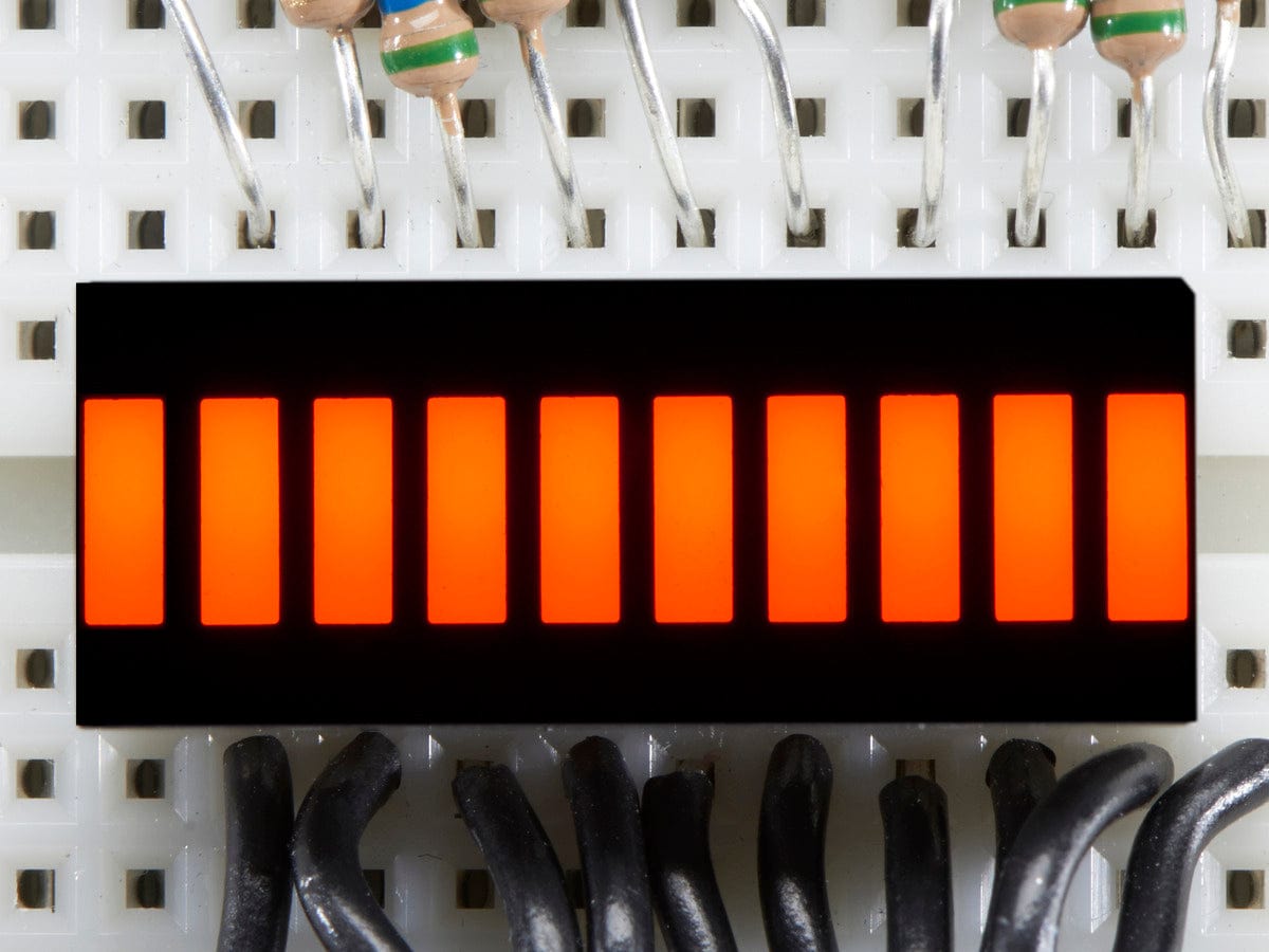
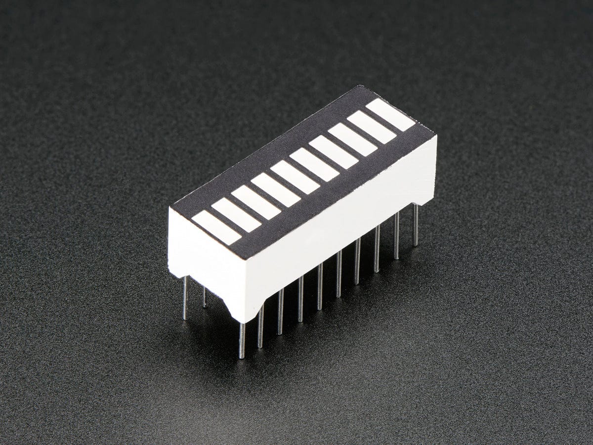
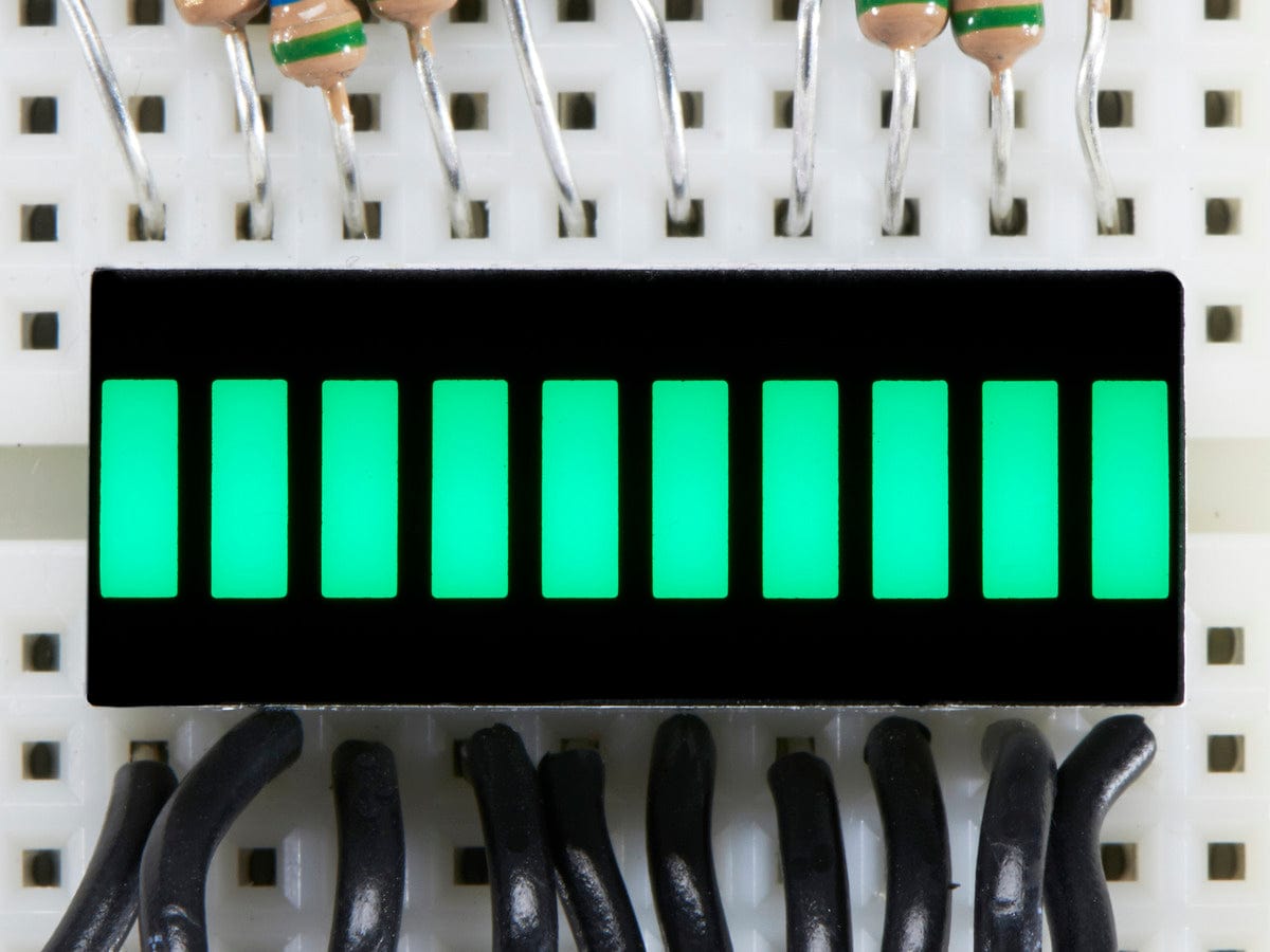
We are now going to use our code to control ten LEDs in a row. You can either use individual round LEDs, or a rather neat package with ten rectangular LEDS called a Light Bar / Bar Graph.
Each LED will need its own 330 Ohm resistor and an individual connection to a pin on the Pico. We are going to use GP2 to GP11 to control the LEDs.
Here is a picture of our circuit. Our 10 segment LED had the anode legs on the side with the printing and the cathode legs on the blank side:

The Raspberry Pi Pico has convenient pin numbers printed on its underside making it much easier to connect jumper wires to the correct pin.
We have kept the button on GP 15 and the potentiometer on ADC0 – GP26.
The LEDs have their anodes connected directly to the Pico’s GPIO pins (GP2 to GP11) while the cathodes are connected to the GND rail via 330 Ohm resistors.
Need a reminder on anodes and cathodes? Go back to episode #1 where this is covered.
Test the LEDs
Copy the code below over to your Thonny window and run it - we'll explain how it works in a moment:
How It Works
The first section imports the necessary libraries and sets up the button. We then set up the list of LEDs like this:
We start with an empty list called leds, using leds = [] # An empty list.
There are ten LEDs so we can use a counted loop to repeat a section of code ten times. In the loop we set up a new LED on GP pin 2 + i, where i is the loop counter, running from 0 to 9. Initially, this is pin GP2 and finally GP11.
We then append the newly created LED to the growing list and make sure that it is turned off.
Once the LEDs have been set up, we can start turning them ON and OFF in different pattens:
- Turn them all ON, one at a time
- Turn them all OFF, one at a time, in the opposite direction
- Flash them ON/OFF one at a time up then down the row
- Flash in random positions 30 times
Controlling a List of LEDs with a Potentiometer
Let's use the potentiometer (pot) in our circuit to control the LEDs. Copy the code below over to Thonny, run it, then read on for to learn about how it works:
The lit LED should appear to move up and down the row.
Press the button to break out of the loop and then turn the knob of the potentiometer to control what is going on.
How It Works
Let's take a look at the two main code blocks:
First a single LED moves as the potentiometer is twisted.
After pressing the button again, we get a solid bar graph controlled by the pot. Press the button once more to finish and clear the display.
This loops while the button is released. The first line in the loop calculates an integer value from 0 to 10 inclusive from the value obtained from the potentiometer.
If the value is zero, we want the display OFF so that we do not turn any LEDs ON. We calculate the pointer value by subtracting 1 from pot_in, getting values 0 to 9 as required for 1 to 10 LEDs. The current LED is only on for 1/10th of a second in each loop but we do not see the flicker because of persistence of vision.
This is an example of nested loops - loops running inside an outer loop. Here the outer loop is button controlled - it keeps looping until the button is pressed.
Inside the loop we get a raw value from the potentiometer, scale it to the range 0 to 10 inclusive and print it in the Shell window.
The first inner loop turns off all the LEDs. The pointer, has the values: 0, 1, 2, 3, 4, 5, 6, 7, 8 and 9.
The second loop, which lights up some of the LEDs, only runs if the scaled value from the potentiometer is greater than 0. If pot_in is equal to zero it does not enter the loop. Otherwise, it lights up the number of the LEDs equal to pot_in. If pot_in equals 4, we need to light 4 of the LEDs and the pointer, p, has the values 0, 1, 2, 3, lighting up the first four LEDs (It’s all about humans counting from 1 and computers from zero).
Things to try
- Bounce a pair of adjacent LEDs up and down the display – always showing 2 lit LEDs
- Bounce two lit LEDs at the same time starting with one at each end of the display
If possible, please keep the current circuit as we'll be using it in the next tutorial when we learn about subroutines (procedures and functions).
About the Author
This article was written by Tony Goodhew. Tony is a retired teacher of computing who starting writing code back in 1968 when it was called programming - he started with FORTRAN IV on an IBM 1130! An active Raspberry Pi community member, his main interests now are coding in MicroPython, travelling and photography.
We used Fritzing to create the breadboard wiring diagram images for this page.

1 comment
Neil Hoskins
With the ten flashing LEDs, it should be p = random.randint(0,9) not p = random.randint(1,9) otherwise the first one never lights.
With the ten flashing LEDs, it should be p = random.randint(0,9) not p = random.randint(1,9) otherwise the first one never lights.