

Let it Glow Maker Advent Calendar Day #7: Time to Slide!
It’s day #7 of the Let it Glow Maker Advent Calendar!
Today we're jumping back to a control component - something we can use to physically control our blinky components, with our code being the brains between the two.
The slide potentiometer in your box will allow us to smoothly increase and decrease a reading which we can use to change flashing speeds, colours and more using analogue signals - a great companion for LEDs and other blinky bits!
Let’s 'slide' straight into it...
Box #7 Contents
In this box you will find:
- 1x 45mm slide potentiometer
- 1x Cap for slide potentiometer
- 3x Male to male jumper wires

Today’s Activities
Today we’re going to learn how to use this analogue slide potentiometer, including understanding what a potentiometer is, how they work, how the Pico can take analogue readings from them and ultimately how we use those readings to make things happen with our code and LEDs.
Let's first talk about potentiometers and analogue signals...
What is a Potentiometer?
A potentiometer is a variable resistor.
Our calendar already included a traditional resistor for the LED in box #2, but that resistor was at a fixed value offering a specific amount of resistance. A potentiometer is a resistor that can have its value changed (in our case, by sliding the knob up and down).
The slide potentiometer in your box is a 10K potentiometer, meaning it can be set anywhere from 0 ohms to 10,000 ohms (resistance is measured in ohms).
The way we're going to wire our slide potentiometer allows us to use it to send a varying voltage value to our Raspberry Pi Pico, which some special analogue pins can read, convert and provide a value we can use in our projects.
What is Analogue?
Until now, we've been using digital signals with the buttons and LEDs in our calendar. Digital signals are strictly a 1 or a 0, HIGH or LOW, ON or OFF. It's one or the other and nothing in between.
Analogue signals offer a wide range of numbers to represent values instead, which is much more suitable for sensors, dials, sliders and similar components.
Think of digital as a light switch - it's either on or it's off. Think of analogue as a volume dial on a stereo - you can twist the dial to gradually turn the volume up and down by smaller amounts.
Our slide potentiometer can pass these analogue signals (in the form of voltage) to our Raspberry Pi Pico, giving us a gradual input with a wide range of values for us to play with in our code.
Construct the Circuit
As always, make sure your Pico is disconnected from the USB cable when working on the circuit.
Prepare the breadboard
Leave your RGB LEDs where they are, as we'll be using them later on.
Your starting point should look something like this:

Fit the slider
These sliders are too long to fit into one breadboard, which is exactly why we asked you to join the two breadboards on day #1!
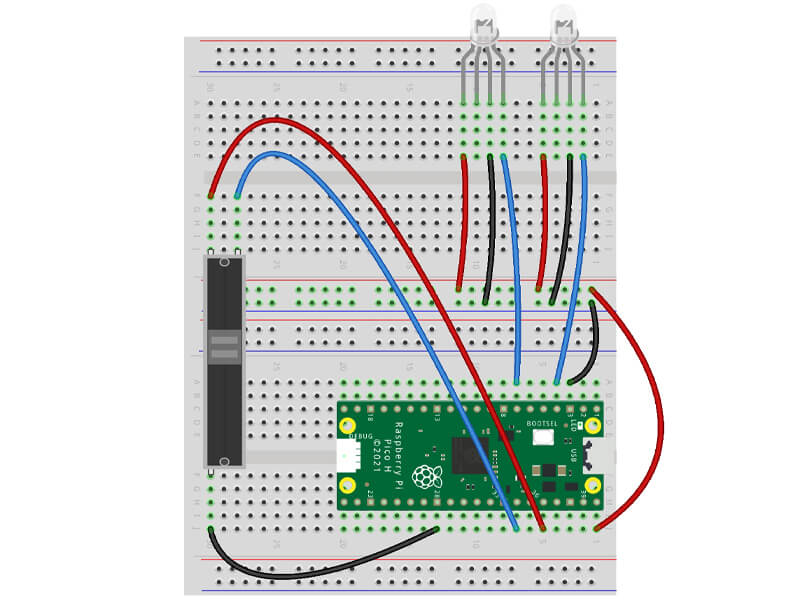
You need to fit the legs so that they go across both breadboards. We suggest copying the legs/holes we have used below, with the two legs at the back, and the single leg at the front.
You also need to push on the little slider cap/knob at this stage if it's not already fitted:

Connect the slider legs
You just need three jumper wires for this part:
- Connect the lower single leg to a ground pin - we've used physical pin 28
- Now connect the top-left leg on the slider to the 3.3V pin - that's physical pin 36
- Lastly connect the top-right leg on the slider to GPIO28 (physical pin 34) - this is a special ADC pin (we'll explain in a moment)
Your breadboard should look something like this:
Activity 1: Showing the slide!
Let's start with a simple program that prints analogue values
We're specifically using GPIO28 as this is one of the Pico's ADC pins. But what is an ADC?
ADC Pins
If you look at our Pico pin map again, you'll see that there are three dark green ADC pins available on the right - GPIO26, 27 and 28 (physical pins 31,32 and 34).
An ADC is an Analogue to Digital Converter. The ADC pins on our Pico have the special ability of being able to convert an analogue input into a digital form we can use. We have to import ADC in our code to use this feature.
Note: You'll also spot ADC_VREF and AGND pins, but we're not going to go into those pins in this calendar as we don't strictly need to use those for our example - we'd rather not overcomplicate things whilst we're still learning.
The Code
The code below imports ADC and sets GPIO28 as an ADC pin, then we start a while loop which prints the potentiometer's value every 0.3 seconds.
The read_u16 part does this, taking the varying voltage applied to the pin from the potentiometer and scaling this to range of usable output values between 0 and 65535.
(For those who want to get technical - the Pico's ADC pins are 12-bit, however MicroPython scales this to a 16-bit range which is 0-65535).
Run the code below and then try turning the dial - watch the values go up and down as you move the slider (the values jump around a bit, and don't always go right down to zero, this is normal). This is where everything above should start to make sense:
# Imports
from machine import ADC, Pin
import time

# Set up the slider on ADC pin 28
potentiometer = ADC(Pin(28))

while True: # Loop forever

    print(potentiometer.read_u16()) # Read the potentiometer value

    time.sleep(0.3) # Short delay until the next reading
Activity 2: Sliding colour changer
Our slide potentiometer gives us a value in a wide range depending on which position it's in, so let's use that to drive some if/elif statements, this time with conditions that look to see if the value is higher, lower or between a set range, to control the colour of our LED based on the value!
Less than, greater than or between?
In our example below, we check if the analogue reading is less than 20000, between 20000 and 40000, or greater than 40000:
- To make our if statement look for 'less than or equal to', we use a <= operator, like this: if reading <= 20000
- To make our if statement look for a value 'between' two numbers, we use a slightly less-obvious combination of two < operators, like this: if 20000 < reading < 40000
- To make our if statement look for 'greater than or equal to', we use a >= operator, like this: if reading >= 40000
Inside each if statement is the same code we used yesterday to control the RGB LED, using red/amber/green colour variables (a bit like traffic lights!)
The Code
Copy the code below over to Thonny and give it a spin, then why not try adding more elif statements, splitting the range even further to add more colours from yesterday?
# Imports
import time
from machine import Pin, ADC
from neopixel import NeoPixel

# Set up the slider on ADC pin 28
potentiometer = ADC(Pin(28))

# Define the LED pin number (2) and number of LEDs (1)
GRBled = NeoPixel(Pin(2), 1)

# Define a few basic GRB colour variables
red = 0,255,0
amber = 255,175,150
green = 255,0,0

# Create a variable for our reading
reading = 0

while True:

    reading = potentiometer.read_u16() # Read the potentiometer value and set this as our 'reading' variable value

    print(reading) # Print the reading value

    time.sleep(0.1) # short delay

    if reading <= 20000: # If reading is less than or equal to 20000

        GRBled.fill((red))
        GRBled.write()

    elif 20000 < reading < 40000: # If reading is between 20000 and 40000

        GRBled.fill((amber))
        GRBled.write()

    elif reading >= 40000: # If reading is greater than or equal to 40000

        GRBled.fill((green))
        GRBled.write()
A quick challenge!
The code above lights up one LED only. Your challenge is to make both LEDs light up instead of just the one. Remember to:
- Make sure you give the LEDs different names and the right pin numbers
- Add the code where required to turn the other LED on
- Use the different LED names in the code too!
Activity 3: Slider fader
Let's now make use of the analogue reading to control the GRB value (0 to 255 if you remember) of our LED, allowing us to fade it in and out using the slider!
Rather than using if statements looking for a range of values, we'll inject the number directly into our GRB LED code, however we'll need to crunch the numbers here, because our analogue range is 0 to 65535, but our GRB value only runs from 0-255.
To do this, we'll need to convert the reading and use the round function. Hold on to your socks folks - it's time for some maths!
Converting number ranges
Here's how we will convert the ranges. It might be worthwhile to follow along with a calculator to see it yourself:
- We need to take the GRB value range (255) and divide it by the analogue reading range (65535)
- This gives us 0.0038910505836576
- Every time we take an analogue reading, we need to multiply it by that number
- Let's say the analogue reading was 40249 - this would be 40249 x 0.0038910505836576 = 156.6108949416347
- Our GRB code doesn't want decimal places (floats) like the big long one above, so we need to round this number - to do that we use the round function
- The round function looks at our number (156.6108949416347) and takes it to the nearest whole number, which means it will round up to 157
- Our code can now automatically convert any reading that our slider gives us into a useful value for our RGB LED.
You may want to read that a few times to get your head around it!
The Code
A few other things to mention about the code example below:
- We create two variables - one for the analogue reading (analoguereading) and another for the converted RGB value (rgbvalue). This allows us to print the original values next to the converted RGB value to see what's going on.
- You'll notice we print some text followed by the variable. This is achieved by entering the text string in inverted commas, followed by a comma, then the variable name. For example: print("my text here",variablename)
- We also use some extra blank spaces to align the numbers in the shell window when they print, such as: "RGB: "
- The number conversion and rounding is all handled in a single line of code with rgbvalue = round(reading * (255 / 65535))
- We could have shortened our code by taking the analogue reading as part of the same line as well, but it's complicated enough without adding more on a single line! For example rgbvalue = round((potentiometer.read_u16()) * (255 / 65535))
Time to try it for yourself!
# Imports
import time
from machine import Pin, ADC
from neopixel import NeoPixel

# Set up the slider on ADC pin 28
potentiometer = ADC(Pin(28))

# Define the LED pin number (2) and number of LEDs (1)
GRBled = NeoPixel(Pin(2), 1)

# Create a variable for our analogue reading
analoguereading = 0

# Create a variable for our converted GRB value
GRBvalue = 0

while True:

    # Read the potentiometer value
    analoguereading = potentiometer.read_u16()

    # Take the analogue range (65535), divide it by the GRB range (255)
    # Then take the analogue reading and multiply it by that number
    # Round the number as our RGB code does not want floats (decimal places)
    GRBvalue = round(analoguereading * (255 / 65535))

    # Print the values, with text to indicate which is which
    print("Analogue: ",analoguereading) # original analogue value
    print("GRB:      ",GRBvalue) # converted RGB value

    # Light the LED with the converted BRG value
    GRBled.fill((0,0,GRBvalue))
    GRBled.write()

    time.sleep(0.1)
Activity 4: Slider flash speed control
Blinky isn't blinky unless it blinks, so let's use our slider to change the speed of a flashing LED. We'll do this by creating a simple variable and directly using the analogue value to update that.
We'll also make this a little more interesting by adding random colour changes for each flash as well - oh how very festive indeed!
Tip: Using variables for time delays can be useful in other ways too. If your code includes lots of similar delays in different places, updating a single variable can save you a lot of time. For example, you can simply use time.sleep(myvariable) throughout your code, then just update myvariable to whatever you want the delay value to be, and it'll change everywhere!
The Code
We'll need to import random again, and create an initial variable for our flash delay (we called it 'flash').
Inside our while loop we update our 'flash' variable by taking the analogue reading and dividing it by 65535. We do this because - and this is quite handy - the analogue range (0 - 65535) divided by 65535 gives us really useful small values for a time delay range. The largest number will be 1 second (65535 / 65535) which is about as high as we'd want to go for a flashing LED.
We also create three variables - g, r and b - and use random to give us a random number for each between the range we have set, which is 0 to 255. Then when we fill the LED, we inject those variables as the GRB colours using GRBled.fill((g,r,b)).
The time delay is the final part of our code, using our flash value with time.sleep(flash).
Give the code a try:
# Imports
import time
from machine import Pin, ADC
from neopixel import NeoPixel
import random

# Set up the slider on ADC pin 28
potentiometer = ADC(Pin(28))

# Define the LED pin number (2) and number of LEDs (1)
GRBled = NeoPixel(Pin(2), 1)

# Create a flash speed variable
flash = 0

while True:

    # Read the potentiometer value
    flash = potentiometer.read_u16() / 65000

    # Generate random GRB values
    g = random.randint(0,255)
    r = random.randint(0,255)
    b = random.randint(0,255)

    # Light the LED with the random GRB values
    GRBled.fill((g,r,b))
    GRBled.write()

    # Delay based on slider position
    time.sleep(flash)
Day #7 Complete!
We hope you enjoyed today's activities. Things are getting a lot more interesting and blinky now, with more of that to come!
You might be feeling a little frazzled from the more complicated examples and maths used today. As always, we suggest going back over anything that you're not 100% comfy with, as well as playing with the numbers and variables in the code to see the changes for yourself - it can really help to make things stick.
Your growing toolbox of MicroPython knowledge should start making you consider projects you can make, such as...
- Can I use the bar graph with the slider?
- Can I change the LED colour with the button whilst changing the flash speed with the slider?
- Can I use the slider to fade the light between two LEDs?
- And more!
This is the ultimate aim of this calendar, giving you the knowledge and code examples to empower you to create your own projects and ideas!
Recap time - today you have:
- Learnt about potentiometers
- Learnt about analogue signals
- Created a circuit with a slide potentiometer
- Learnt about the Pico's ADC pins and how to use them in MicroPython
- Used less than/more than/equal to with if statements
- Converted number ranges using maths in MicroPython
- Mixed text with variables in print functions
- Learnt about the round function
- Used the random function to generate colours
Tomorrow is another blinky day and it's another of our favourites! Leave your circuit as it is, get a good night's sleep and rest that growing maker brain.
See you first thing in the morning!
We used Fritzing to create the breadboard wiring diagram images for this page.


20 comments
Nick
Loving this calendar even as a veteran coder of quite some years,
Never touched a raspberry Pi before, but takes me back to fun times with my BBC micro and all the IO ports it had, this is as much fun!
( also have to agree with Simon above, bit shifting seems much more appropriate than divide for a microcontroller )
The Pi Hut
@Alex – thanks for the comment. We’ve updated the text (better late than never 😬)
@Alex – thanks for the comment. We’ve updated the text (better late than never 😬)
Nick
I had the same problem with the slider reading not changing but after reading the comments
Changing to ADC Pin 27 fixed it
I had the same problem with the slider reading not changing but after reading the comments
Changing to ADC Pin 27 fixed it
Fellow Programmer
I Just wanted to Say Thank you these computing classes are amazing for my 11 year-old son.
I Just wanted to Say Thank you these computing classes are amazing for my 11 year-old son.
Alex
Hey! Big thanks for the great calendar so far!
Introducing electronics and basic programming to my 8y old dauther this way was lots of fun.
She really loves the ‘unicorny’ colors!
Maybe we spotted a little typo in the code explanation of activity 4, noting critical.
In “… we inject those variables as the GRB colours using GRBled.fill((r,g,b)).”
Should rather be “.. GRBled.fill((g,r,b))”. The code is correct though.
Thanks again for the great content!
Harlan
Amazing advent calendar, well done! Tried making it so that if the code on the website only lights one led it lights two. It worked!
Amazing advent calendar, well done! Tried making it so that if the code on the website only lights one led it lights two. It worked!
Simon Craig
I have a suggestion about dropping the 16 bit integer of the potentiometer to an 8 bit integer.
I know they way suggested here works but this is just to think about.
We have multiply and divides that then has to be turned back into an integer.
Or we could right-shift the number. This shifts the binary digits to the right.
So x>>8 will take x ( our 16 bit integer) and shift the binary to the right 8 places. This gives us an 8 digit integer.
In larger programs this will save on processing speed. But it also might also be easier in some people’s heads.
Chris
Problem is solved. Have moved the slider mechanically a few times hard up and down and now the values are perfect!
Problem is solved. Have moved the slider mechanically a few times hard up and down and now the values are perfect!
Paul
My slider did report 65K at the top, but at the bottom it only got as low as 400ish. This causes the LED to flicker instead of going off.
To correct this, “calibrated” my slider in the code by reducing the value by 500 (and checking it doesn’t give a negative number):-
analoguereading = (potentiometer.read_u16() – 500)
if (analoguereading < 0):
analoguereading = 0
Then in the conversion to RGB values, also reduce the value in the division by 500. So
GRBvalue = round(analoguereading * (255 / 65535))
becomes
GRBvalue = round(analoguereading * (255 / 65035))
Paul
@Andrew, thank you.
The switch the 2 wires has fixed the non-linear potentiometer . It is working now!
@Andrew, thank you.
The switch the 2 wires has fixed the non-linear potentiometer . It is working now!
The Pi Hut
@Chris – OK, if Andrew’s comment below doesn’t help, please get in touch with our support team via support.thepihut.com and they will help with a replacement.
@Chris – OK, if Andrew’s comment below doesn’t help, please get in touch with our support team via support.thepihut.com and they will help with a replacement.
Andrew
For the people finding that their potentiometer doesn’t appear to be linear – I had the same problem.
Check your wires from the two pins at the top of the potentiometer in the wiring diagram and notice that they effectively switch over when connected to the Pico. The left potentiometer pin connects to the right most Pico pin in the diagram.
Hope that helps
Chris
Hi
I double checked the wiring and it is placed as showed and connected to the 3.3V pin, GPD27 (before 28) and GND. For me it looks like a sad behavior of the slide potentiometer.
Regards, Chris
Hi
I double checked the wiring and it is placed as showed and connected to the 3.3V pin, GPD27 (before 28) and GND. For me it looks like a sad behavior of the slide potentiometer.
Regards, Chris
The Pi Hut
@Chris – Can you check your wiring for me please? I have a suspicion you may have connected the slider to the 5V rail rather than the 3.3V pin (or some other wiring error). Thanks.
@Chris – Can you check your wiring for me please? I have a suspicion you may have connected the slider to the 5V rail rather than the 3.3V pin (or some other wiring error). Thanks.
The Pi Hut
@TimR – Thanks Tim, I think we spotted it (we incorrectly described it as dividing 65535 by 255, and not 255 by 65535). The description has now been updated.
@TimR – Thanks Tim, I think we spotted it (we incorrectly described it as dividing 65535 by 255, and not 255 by 65535). The description has now been updated.
Chris
Hi
Great calendar, well done, thank you.
Can we somehow compensate the slide potentiometer value to be able to use it “more linear”? It reaches the value of 60’000 after 20% of sliding already. Makes it tricky to use the lower values smoothly.
Thanks und best regards, Chris
Hi
Great calendar, well done, thank you.
Can we somehow compensate the slide potentiometer value to be able to use it “more linear”? It reaches the value of 60’000 after 20% of sliding already. Makes it tricky to use the lower values smoothly.
Thanks und best regards, Chris
TimR
Another great little tutorial. I really like the way it explains the why as well as the how, I wish I had had something similar when I got my Commodore 64 many years ago, I might be a better programmer now!
BTW, be careful with the maths in Activity 3, there is an error in the explanation (not the numbers).
The Pi Hut
@Roy – Can you can triple-check your wiring (re-seat everything) and code, and perhaps even try a different ADC pin such as GPIO27? Then if it’s still giving weird readings please ping our support guys via support.thepihut.com and they will be able to help with a replacement.
@Bartosz – Did you receive a support ticket auto-reply email after you submitted it? If not, you may have entered a typo in your email address (this happens a lot) which means we’ll reply to the same (incorrect) email which you’ll never receive. If you did receive the email, the guys might just be catching up as it’s a busy time of year for us, so you should receive a reply today as they work through tickets.
Bartosz
Well, my yesterday item was not correct ( raised with support but still no answer ) and now day 7 uses components from day 6. I’m stuffed.
Well, my yesterday item was not correct ( raised with support but still no answer ) and now day 7 uses components from day 6. I’m stuffed.
Roy
Is my slider broken? At the top it reads about 65k, then in the width of a single human hair it goes to 20k, then for the rest of the slider it jumps between11k and 9.5k, no matter where in the slide it is
Is my slider broken? At the top it reads about 65k, then in the width of a single human hair it goes to 20k, then for the rest of the slider it jumps between11k and 9.5k, no matter where in the slide it is