

Let it Glow Maker Advent Calendar Day #2: Lighting LEDs!
It’s day #2 of the Let it Glow Maker Advent Calendar!
Yesterday we got comfortable with the Pico and learnt about its different features, including some sample code and the onboard LED. Today we’ll build on that by introducing physical components, real life things you can control using the code we’re going to learn over these 12 days!
We’re starting with a fancy blocky LED, which works the same way as a traditional LED - just in nicer clothes!
As the calendar progresses we’ll be using more advanced parts to use with your growing MicroPython knowledge, however these simple LEDs are a really great place to start.
Let’s go!
Box #2 Contents
In this box you will find:
- 1x 15mm diffused ‘blocky’ LED
- 1x Resistor
- 2x Male to male jumper wires

Today’s Activities
Today we’re going to be learning how to construct a simple circuit and coding our blocky LED to light up, flash and more.
We'll also be learning a few new tricks in MicroPython to add to your growing library of knowledge.
Those of you who completed our 12 days of Codemas Calendar last year will be familiar with LEDs as they’re the go-to component for learning how to code. This is why we’ve included a different diffused/blocky style of LED in this year’s calendar, but don't worry, lots of fun new components are coming up!
What is an LED?
An LED is a Light Emitting Diode. These components emit light when electrical current flows through them.
LED Polarity
Standard LEDs have two legs, usually one longer than the other, as they have a specific polarity - which means that electrical current can only flow in one direction (and if not, the LED can be damaged!).
When the legs have different lengths, the long leg is the Anode (+) and the short leg is the Cathode (-). Current always flows from the anode to the cathode.
Our blocky LED doesn’t have different leg sizes. Instead, we use the text on the side of the LED's body to help us identify which leg is which. The leg on the side with text is the anode(+). Be sure to read our wiring instructions below carefully to make sure you get this part right.

What is a resistor?
LEDs usually require a current-limiting resistor when using them with a microcontroller.
Resistors limit the amount of current that can pass through a circuit, which helps avoid the LED trying to pull more current than our Pico's GPIO pins can safely provide, and equally protects the LED from too much current.
It doesn't matter which side of the LED the resistor sits, as long as it's there limiting the flow of current for the entire circuit.
We always like to think of current as water in a pipe. If you had a wide pipe passing water from one end to the other, but a narrow section of pipe in the middle (our resistor), the narrow section is then the bottleneck that determines how much water the entire pipe system can pass through.
Raspberry Pi Pico Pin Map
Here’s a simplified map of the pins on the Pico (known as a pinout) to help you with the next steps and the rest of the calendar.
The numbers in the grey squares are the physical pin numbers which are numbered in order around the board. The GPIO pin numbers which we use in our code are in green (or start with 'GP' if colours aren't helpful to you). You can also download the full PDF version here.

Construct the Circuit
First, make sure your Pico is disconnected from the USB cable. You should always do this when building or amending a circuit. Then grab the jumper wires, resistor and the LED.
Breadboards
We're going to be adding components to our breadboards. Breadboards allow you to connect and prototype a circuit without soldering, using wires with pins at the end called jumper wires (sometimes called DuPont wires).
These breadboards each have two sets of horizontal channels (red/blue) on both sides. All the red pins are connected, as are the blue (but each red/blue side is disconnected from the other). We use these to create 'rails' of connections for us to use, such as Ground (GND) for the blue channel and 3.3V for the red.
The holes in the middle are connected in vertical lanes, with each lane having 5 connected pins either side of the divider. The divider stops both sides connecting together.
The Circuit
First, take a quick look at the image below for context before you start.
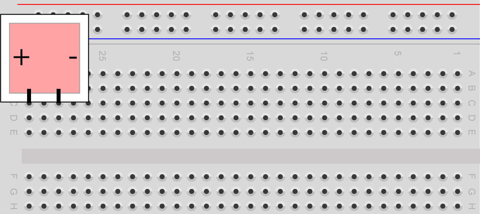
Place the LED into the top-left section of the breadboard. The leg spacing of this LED requires it to have an empty breadboard lane between the two legs.
The anode(+) leg (with the text on the side) goes to the left. Your breadboard should look something like this:
We now need to add a resistor to limit the current that the LED can draw from our GPIO pins.
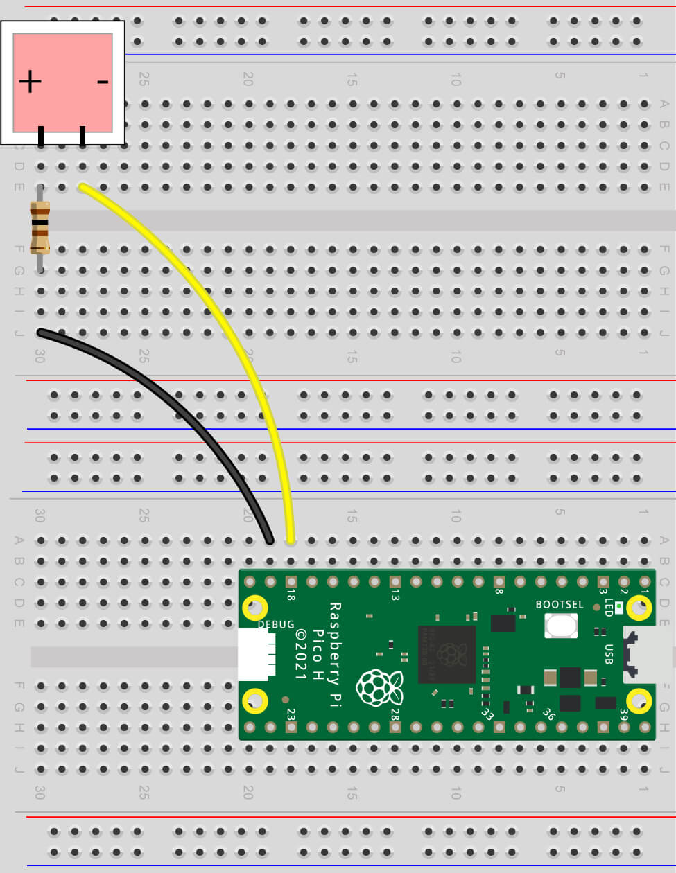
Place the resistor between the left leg (anode +) and the lane below the middle break – see the image below to help make sense of that:

Now grab the two jumper wires. You need one wire connecting the right leg to a ground pin (sometimes shortened to ‘GND’) on your Pico – we suggest using physical pin 18 like we’ve done in the diagram below (remember to refer to the Pico pinout if you need a reminder).
You also need to connect the left leg to a GPIO pin to allow us to control it with code. Use GPIO14 (physical pin 19) like the diagram below.
A few tips & pointers
- It doesn't matter which colour jumper wires you use, they all work the same way. In an ideal world we would reserve black for ground connections and red for voltage, but for simple projects it's not essential (and you’ll find you never have the right amount of colours you need in your stash!)
- If your LED doesn’t light up when you run the code activities below, give the parts a little wiggle – breadboards aren’t perfect and sometimes resistor/LED legs aren’t quite making the connection they need
- You should always double-check your wiring before turning anything on
We’re all set up and ready to code – plug your Pico back in to the USB cable and let’s get to it!
Activity 1: Light the LED
Something simple to start with, just to check everything is working as expected.
We’re going to repeat the code we ran on the Pico’s internal LED yesterday. It works the same way, setting a pin HIGH (on), but we just need to change the GPIO number to our new LED instead of the internal one.
Note: Assuming you turned off your computer after yesterday’s box, you may need to jump back into Thonny and select Run > Configure interpreter again to detect the Pico. Sometimes just hitting the red 'stop' button can help too.
The Code
Let’s recap on how these code lines work - we import Pin from machine to allow us to use the GPIO pins, then define the pin number we connected it to (14), set it as an output and then set the pin value to 1 (HIGH). We also added a print line to show us what's happening in the Shell window too
Here’s the code to copy into Thonny and then run in the usual way by hitting the green button. As before, try setting the value to 0 to turn it off again:
from machine import Pin

blockLED = Pin(14, Pin.OUT)

blockLED.value(1)

print("Block LED on!")
Activity 2: Light both LEDs
We know how to light each LED by changing the pin number – that’s easy – but what if we want to light both LEDs (the Pico's onboard LED and our blocky LED) at the same time?
This is easy to add into our code as you just need to duplicate some lines and change the pin being referenced. You’ll do this kind of thing a lot when you make more advanced projects with multiple components for your code to talk to.
The Code
Take a look at the example below – we’ve used the name ‘green’ for the onboard LED, setting it up with GPIO25, and have used this in an additional line turning the LED on. We also changed the blocky LED name to 'red'.
Copy this example over to Thonny and hit the green button to give it a try:
from machine import Pin

green = Pin(25, Pin.OUT)
red = Pin(14, Pin.OUT)

green.value(1)
red.value(1)

print("Both LEDs ON!")
Activity 3: Flashing LED - Basic
Let’s step things up a gear and get our LEDs flashing - the basics of festive decorations!
To make our LED flash, we need to introduce the time module.
The Time Module
The time module allows you to program delays in your code, making it wait for seconds or fractions of seconds before continuing. It’s a fundamental module you’ll use in most of your projects as we often need to create delays in our programs.
The Code
We’re going to be adding to the code example we just used in activity 2.
We need to import the time module to be able to use it, so our import section now includes this on line number 2.
Then, to make our light flash (turn on and off with a delay) we just add a time.sleep(1) after turning it on (keeping the LED on for 1 second), and then we turn off the LED by simply changing the last number to a 0, followed by another time delay, and repeat this pattern a couple of times.
Take a look at the example below then give it a try, as always, copying it over to Thonny and using the green button to run it:
from machine import Pin
import time

red = Pin(14, Pin.OUT)

red.value(1)
time.sleep(1)

red.value(0)
time.sleep(1)

red.value(1)
time.sleep(1)

red.value(0)
time.sleep(1)
Activity 4: Flashing LED – using Loops
The example above shows the basics of making an LED flash, but it’s not the best way to achieve that result and would end up requiring a LOT of lines to flash the LED for longer than a few seconds!
We can make code loop over and over again using something called a while loop. Let’s introduce these handy loops, and quickly cover indentation and code commentary before we get to the example.
While Loops
While loops are used to repeat a block of code as long as the condition remains true.
Imagine you're driving a car around a racetrack. Your condition might be "drive 5 laps around the track". After 5 laps, you'd stop the car.
We can tell a while loop to run a block of code until a condition is met, or we can just make it repeat forever by using 'while True' which is useful for projects intended to keep running.
For this first loop example, we’ll just make our loop run forever (until we stop the program manually) using while True.
Code Commentary
We’re also going to start adding commentary in our code examples from here on in.
You can add comments in MicroPython code by adding a # before the comment. This will be ignored by MicroPython allowing you to write whatever you want.
Adding commentary makes explaining your code easier to others or as a reminder to yourself when you return to a project. We also like to use it to section out different parts such as the imports, pin setup etc. It’s a very good habit to get in to and allows us to explain each line clearly as our activities get more detailed over the twelve days.
If anything, at times we'll probably be over-doing the commentary to make sure things are very clear for you (this can be seen as bad practice but we think it's better to make sure things are understood!).
Code Indentation
Indentation is a gap at the front of a line of code, usually a tab space or a number of spaces.
It's very important in MicroPython as it tells Thonny that the lines belong to a particular block of code (in our example below, we've indented the lines under the while loop as the code belongs to that loop).
The Code
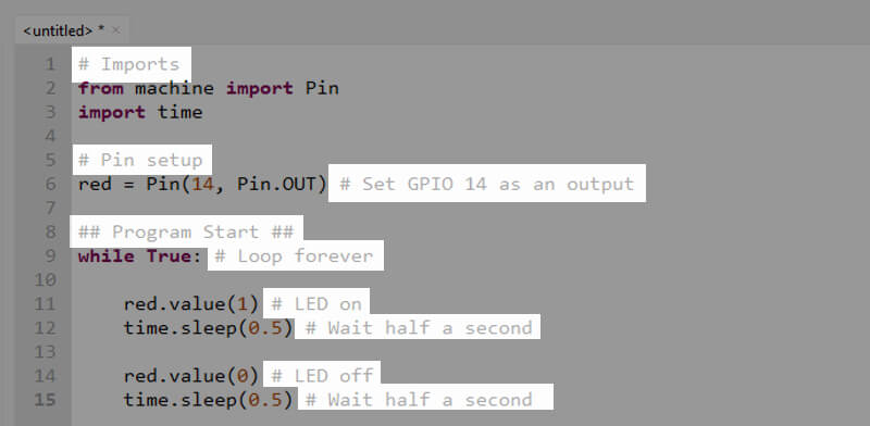
The code below first imports the things we need for our program, and sets our pin numbers up as we've done before.
Now, instead of jumping straight into a line to control the LED, we start a while loop and place our code inside that. We use while True: which starts a block of code that will run forever. Anything we want to run as part of this loop needs to go underneath it and indented.
Our indented code turns the LED on, waits half a second (using 0.5), turns the LED off again, then waits another half-second. As it’s in a while true loop, it’ll go back to the top of the intended code and run it all over again and again until we stop it.
Also notice we've added somewhat over-the-top commentary. You can add comments on their own lines, or even after code - we've done both just to show you.
Copy this code over to Thonny and run it in the usual way using the green button. When you want to stop the program, just select the red button:
# Imports
from machine import Pin
import time

# Pin setup
red = Pin(14, Pin.OUT) # Set GPIO 14 as an output

## Program Start ##
while True: # Loop forever

    red.value(1) # LED on
    time.sleep(0.5) # Wait half a second

    red.value(0) # LED off
    time.sleep(0.5) # Wait half a second
Activity 5: Flashing LED – a set number of times
The example above gives us a flashing LED ‘forever’, but what if we only wanted it to flash a certain number of times?
We can do that a couple of ways, and the method we’ll use this time is the range function.
The Range Function
The range function is really handy when you want to repeat something a certain number of times.
Let's say we wanted to flash our LED ten times. Well, we could add ten sets of on/off code, but that’s inefficient to write and maintain. It also uses a lot more lines than other methods, which is important when you’re working with microcontrollers as they sometimes have very limited storage space.
A better way to do it is using range - and this is how it would look:
## Imports ##
from machine import Pin
import time

## Pin setup ##
red = Pin(14, Pin.OUT) # Set GPIO 14 as an output

## Program Start ##
for i in range(10): # Run the indented code below 10 times

    red.value(1) # LED on
    time.sleep(0.5) # Wait half a second

    red.value(0) # LED off
    time.sleep(0.5) # Wait half a second

print("Program finished")
Don't get hung up on why the 'i' is an 'i' - change it to a 't' or a 'v' and see what happens - it's the same outcome! Traditionally 'i' has always been used so most programmers stick with that. Consider that the 'i' means iteration or index and it starts to make more sense..."for every iteration within the range of 10"...make sense?
For now, all you need to know is that the number in brackets (10) is how many times our indented code will run. It will start at zero and loop for as many times as the number in the brackets (10). We'll return to the range function again so don't worry if it looks scary just now.
Copy the code above over to Thonny and give it a spin! Notice we've added a final print line that isn't indented. That's because once our range loop is finished, the code will 'break out' of that and carry on as usual.
Day #2 Complete!
We packed a lot of new code knowledge into today's box - this will come in handy for the following days where we’ll be combining these new functions and skills, along with more, to create some fun projects.
It’s only day two, so don’t worry if you’re not 100% confident with anything we covered today, we’ll be going over things again with more examples in the upcoming boxes.
Let’s recap – what did we cover in today’s box?
- What LEDs and resistors are
- Anodes and Cathodes
- How breadboards work
- Constructing an LED circuit
- Coding with multiple components/pins
- The Time module
- While loops
- Code commentary
- Code indentation
- The Range function
Keep your circuit safe until tomorrow (don't take anything apart yet) and we'll see you after breakfast!
We used Fritzing to create the breadboard wiring diagram images for this page.


25 comments
Dale
Gifted this for Christmas by my daughter and enjoying following these guides. My daughter enjoyed watching the LED blink. Hopefully in a couple of years she’ll be enjoying the coding side as well.
Gifted this for Christmas by my daughter and enjoying following these guides. My daughter enjoyed watching the LED blink. Hopefully in a couple of years she’ll be enjoying the coding side as well.
Richard
All working well – added my own print statement to see where in the loop we are.
Resistor is way too skinny to easily push into the breadboard, suggest supplying resistors with fatter pins.
Or! it’s the breadboard being too stiff?
One of my jumper cable pins snapped off. Just as well I have 100s of spares available.
Finally advent is 24 days, so where are the other 12 projects?! ;-)
The Pi Hut
@Fin Apps – Not sure if I understand the pin reference problem. The GPIO wire (on the left in the diagram) should be routing to GPIO14, which is physical pin 19.
Just to check – is it all up and running now? If not, please drop us a message at support.thepihut.com and we can help further.
I’ve asked the team to check the contents too. It sounds like some larger 1/2W resistors may have made it into some packs – which will work fine and perform the same job (some customers prefer these larger versions as they’re easier to handle, and the legs are a little thicker so less prone to bending).
Fin Apps
Dear admin who is reading this and has to approve the comments – my wires were actually next to pin 17 and not pin 14. Truly typos and incorrect references will doom us all. And if these comments both make it through – check if it’s 17 guys!
Dear admin who is reading this and has to approve the comments – my wires were actually next to pin 17 and not pin 14. Truly typos and incorrect references will doom us all. And if these comments both make it through – check if it’s 17 guys!
Fin Apps
I can’t get this LED to light up anymore. Once, the LED light turned on and would not respond to any code input. After unplugging the USB and plugging it back in again, the LED refuses to turn on at all.
Debugging:
1. Is the code correct? – Yes
2. Is the light on the pi responsive? – Yes
3. Is everything plugged in correctly, including the wires being associated with the correct pin on the pi? – Yes
4. (As per other suggestions in the comments) Have you tried moving the wires to lower down on the breadboard and trying again? – Yes. This did not help.
5. Do the bands on the resistor match the bands on the diagram? – Yes
I am running out of ideas! The only thing I can think is that my resistor is comically oversized and blue and black instead of the multi-coloured one in the description? Any additional help would be very appreciated.
The Pi Hut
@Becky – Assuming you’ve checked it’s pushed right down into the breadboard, it sounds like the internal connections inside your breadboard may be out of alignment, which can happen as they move around slightly when we push component legs and wires into them. Usually they self-adjust back into place each time we use them.
Try using a different area of the breadboard (away from an edge ideally) to see if that helps. If no joy, pop our support team a quick message via support.thepihut.com, and we’ll get a replacement LED and breadboard out to you (just mention this comment).
Becky
I cannot get the LED to work unless the prongs on the bottom of it are directly touching the ends of the jumper wires, so the LED works, but not when it is connected to the board. I swapped everything around, but the LED still won’t light up when in the board.
I cannot get the LED to work unless the prongs on the bottom of it are directly touching the ends of the jumper wires, so the LED works, but not when it is connected to the board. I swapped everything around, but the LED still won’t light up when in the board.
Stephen
A fun project to do with my 12yr daughter. She is taking to Python & enjoying experimenting with the I/O. Thanks PiHut!
A fun project to do with my 12yr daughter. She is taking to Python & enjoying experimenting with the I/O. Thanks PiHut!
JezShed
I’m really enjoying this. It’s beautifully put together and beautifully written, thank you!
I’m a old-timer engineer, but sometimes it’s just nice to have my hand held while I try new things (the Pico in my case). I look forward to each box but I’m pacing myself so it last until Christmas Eve.
I’m really enjoying this. It’s beautifully put together and beautifully written, thank you!
I’m a old-timer engineer, but sometimes it’s just nice to have my hand held while I try new things (the Pico in my case). I look forward to each box but I’m pacing myself so it last until Christmas Eve.
The Pi Hut
@Sarah T – Fun isn’t it! We’re very grateful for all the comments too, there’s some great little additional projects being submitted, including a few funny ones (pretty sure there’s a Rickroll hiding in one of the calendar comment sections 😂).
@Sarah T – Fun isn’t it! We’re very grateful for all the comments too, there’s some great little additional projects being submitted, including a few funny ones (pretty sure there’s a Rickroll hiding in one of the calendar comment sections 😂).
Sarah T
Having so much fun with this already and feel like I’m learning a lot about understanding why and how things work! Grateful to others’ comments for suggestions on playing about with the code some more, I’ve managed to change the timings of the lights and whether they blink together or alternate.
Having so much fun with this already and feel like I’m learning a lot about understanding why and how things work! Grateful to others’ comments for suggestions on playing about with the code some more, I’ve managed to change the timings of the lights and whether they blink together or alternate.
Dominic
No matter what I do, I can’t get the box LED to light up.
No matter what I do, I can’t get the box LED to light up.
MatthewB
As well as doing all of the tasks, I also tried to make both lights blink simultaneously. This worked out really well and might add a bit of a challenge. Loving the Calendar!
As well as doing all of the tasks, I also tried to make both lights blink simultaneously. This worked out really well and might add a bit of a challenge. Loving the Calendar!
The Pi Hut
@Bardia – It could be a wiring problem (a common issue with LEDs). Please remove everything from the breadboard, wire it up again (double-checking anode/cathode as per the images) and see how it goes.
If no joy, please get in touch via support.thepihut.com (select “Submit a request” in the top-right corner) and our support team will help with that.
Bardia
LED won’t light, I believe I may have a faulty LED.
LED won’t light, I believe I may have a faulty LED.
Sandy
When I connected the USB, the block LED came on straight away and won’t turn off using code. I checked the internal LED it works fine still. I’m not sure what to do next, can you help?
When I connected the USB, the block LED came on straight away and won’t turn off using code. I checked the internal LED it works fine still. I’m not sure what to do next, can you help?
The Pi Hut
@Vife – Good suggestion, we’ll add that now. Thanks.
@Vife – Good suggestion, we’ll add that now. Thanks.
Vife
may be it is worth saying for beginners that the in python we count starting at 0 for the loop. You can check this by adding `print("Loop number: " + str(i)) # Print the loop number to your loop`
may be it is worth saying for beginners that the in python we count starting at 0 for the loop. You can check this by adding `print("Loop number: " + str(i)) # Print the loop number to your loop`
Neil Thompson
@The Pi Hut oops! I missed that it was the onboard light that was the green light! 🙏
@The Pi Hut oops! I missed that it was the onboard light that was the green light! 🙏
The Pi Hut
@Neil Thompson – the block LED is a red LED only (it doesn’t show different colours like other LEDs can).
@Neil Thompson – the block LED is a red LED only (it doesn’t show different colours like other LEDs can).
Neil Thompson
I have a problem with the block LED in that only the red led seems to work. I have tried playing with the wires and everything seems ok to me but if anyone can spot anything here: https://i.imgur.com/i3B9aPG.jpg I would be grateful.
I have a problem with the block LED in that only the red led seems to work. I have tried playing with the wires and everything seems ok to me but if anyone can spot anything here: https://i.imgur.com/i3B9aPG.jpg I would be grateful.
The Pi Hut
@Tina – So sorry about that, please let our support guys know via support.thepihut.com and they’ll put that right for you.
@Tina – So sorry about that, please let our support guys know via support.thepihut.com and they’ll put that right for you.
Simon Hargrave
:-D
:-D
Tina
My box did not contain and LED looking at the parts list I have day 3 in place of day two had a sneak peak and definitely not in tomorrows box either. Not the end of the world for me
My box did not contain and LED looking at the parts list I have day 3 in place of day two had a sneak peak and definitely not in tomorrows box either. Not the end of the world for me
TimR
I am really enjoying these tutorials, I have done the blinking LEDs before but this is the best explanation of why and how. The test will be transferring this to other situations like the Christmas tree kit.
Good stuff!
I am really enjoying these tutorials, I have done the blinking LEDs before but this is the best explanation of why and how. The test will be transferring this to other situations like the Christmas tree kit.
Good stuff!