
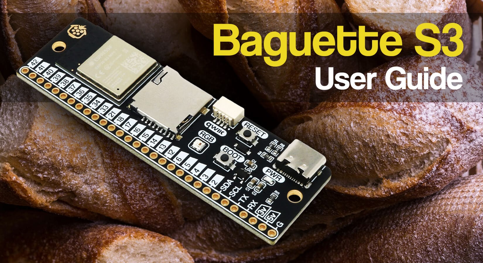
Baguette C3 User Guide
This guide will show you how to use the Baguette C3 ESP32-C3 development board, from the hardware features and specifications through to software setup and example code.
The Baguette C3 is the baby version of our original Baguette S3, which has a few feature and performance differences (fewer features, lower performance, but lower cost and smaller footprint!).
Contents
- Board features
- Powering the board
- Pinout
- GPIO Pins
- Mounting holes
- Boot/programming mode 👉do this first 👈
-
Programming the Baguette C3
- Arduino IDE
- ESPHome via Home Assistant
- MicroPython
- CircuitPython (coming soon)
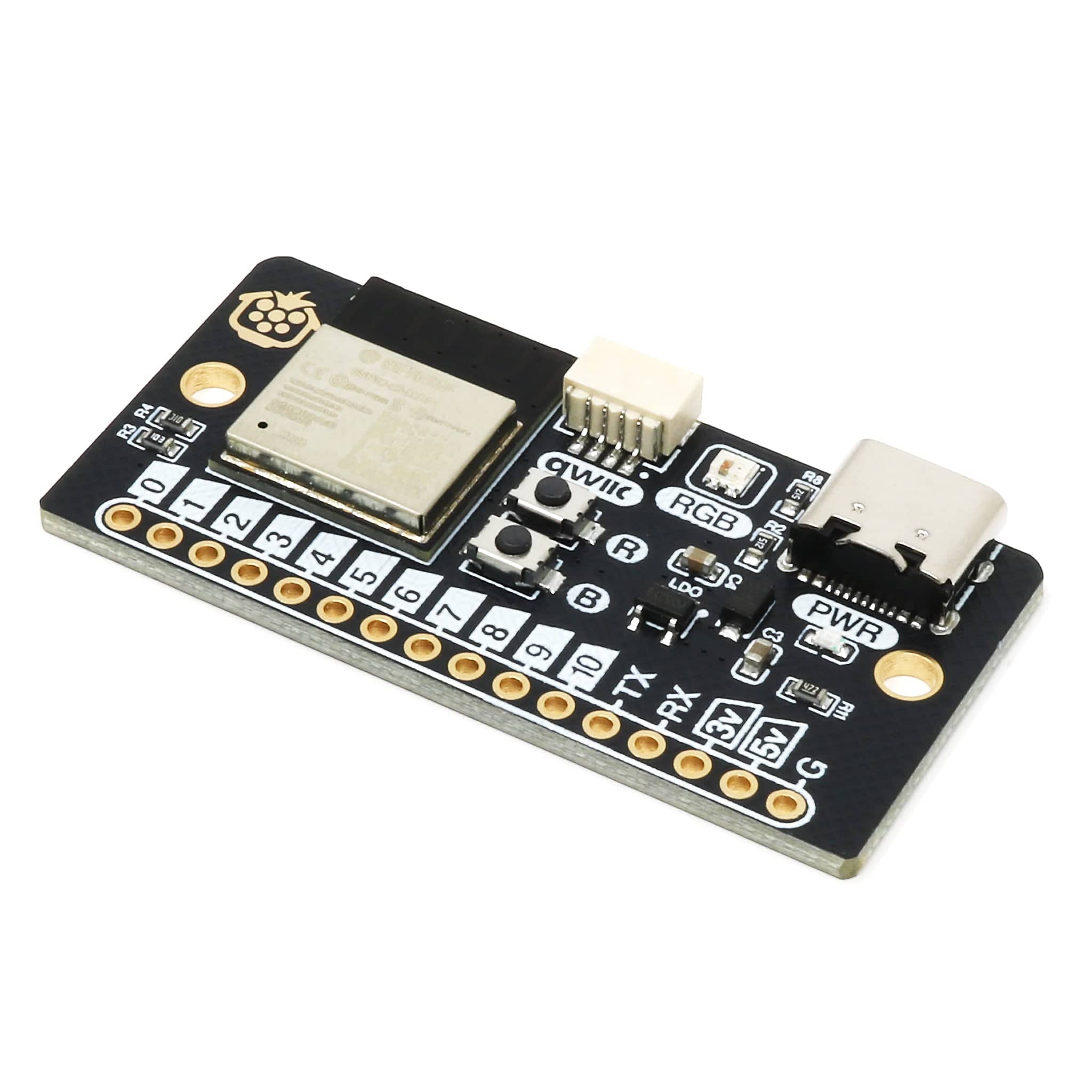
Board features
A quick reminder of the board's features that we will be showing you how to use:

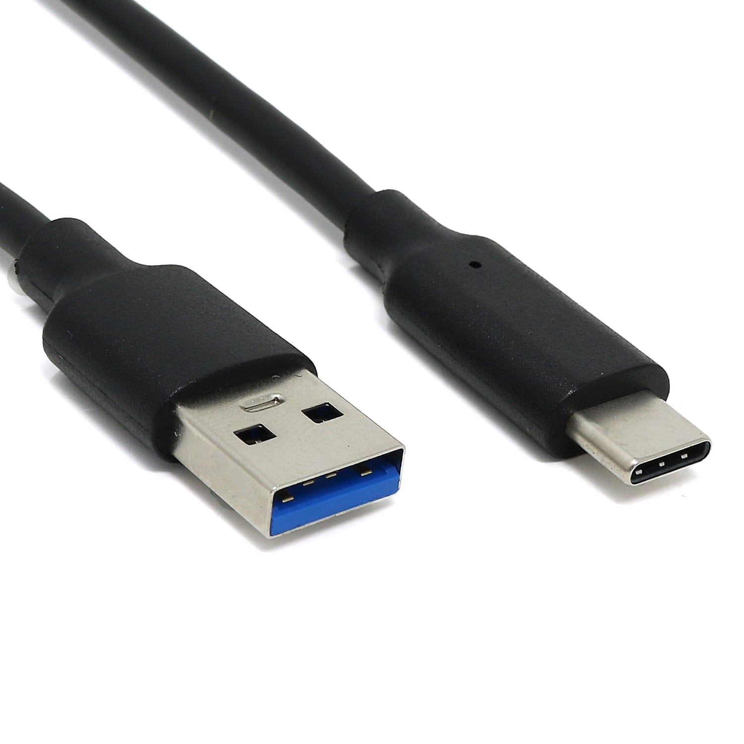
Powering the board
The easiest way to power the board is to use the USB-C port, which also allows a data connection to your PC for programming. An onboard regulator drops this down to 3.3V for the ESP32-C3 module.
When powered, the board's blue 'PWR' LED will be lit.
Powering via pins
If you would prefer to power the board via the pins directly, you have a couple of options here:
-
5V pin - you can connect a regulated 5V power source to the 5V pin (and GND to the G pin)
- This option will then use the onboard regulator to provide 3.3V to the ESP32-C3 module
-
3V pin - you can connect a regulated 3.3V power source to the 3V pin (and GND to the G pin)
- We don't generally recommend this option, as it's best to stick to the 5V pads and let that run through the onboard ME6211 LDO regulator.
Power consumption example
We ran a simple 'real-world' test using the board alongside an mmWave sensor, to give you an idea of power consumption, using our fancy power profiler tool. Click the image for a larger version.
We averaged ~125mA current draw, with a max of ~139mA. Your mileage may vary, as it all depends on what your Baguette C3 is doing and what other hardware it's powering.

GPIO Pins
The Baguette C3 has a 16-pin header, which provides the following functions - many of which are shared (the same pin can be used for different purposes, defined in your code):

Due to the low number of pins available on the ESP32-C3, we decided to break them all out to offer maximum flexibility. As a result, care should be taken when using certain pins for certain functions, as it could prevent the board from booting.
The board offers:
- 11 General-purpose GPIO
- UART (TX and RX)
- SPI (MOSI, MISO, CLK and CS)
- I2C (SDA and SCL)
- ADC (ADC1 and ADC2)
- Power (5V, 3.3V and GND)
- Note: The 5v pin has a voltage of 4.8v due to the power from the USB port being passed through a diode for protection
- Some of these pins are also 'Strapping pins', which is explained below.
Important: Most pins on the ESP32-C3 can be programmed to perform other functions; however, we've documented the default starting positions below.
General IO pins
These are your classic GPIO (General Purpose Input Output) pins for digital IO, setting in your code to output high or low, or define them as inputs.
UART pins
The UART pins (RX/TX) have been separated from the general-purpose GPIO on the board; however, you can use these as GPIO pins if you wish. If not configured, they are HIGH by default.
SPI pins
The SPI pins (MISO/MOSI/CLK/CS) are used to connect SPI devices. These are the 'hardware' SPI pins, however ESP32-C3 pins are fully configurable in software, so you can use other pins for SPI if required.
Not that MISO and CS are shared strapping pins, and CLK is shared with the pin used for the Qwiic port. If you need to use Qwiic (I2C) and SPI at the same time, CLK can be assigned to any of the following pins: 0, 1, 3, 4 or 9.
The ESP32-C3 has three SPI buses, but only SPI2 is available for use by the user as the other two are dedicated for internal flash and PRAM usage.
I2C pins
The I2C pins (SDA/SCL) are used to connect SPI devices. The Qwiic port uses these pins because Qwiic is an I2C-based ecosystem.
- If you are not using the Qwiic port, GPIO5 and GPIO6 can be used for other purposes.
- If you are using Qwiic I2C devices, and connecting I2C devices manually to the pins directly, just make sure the addresses of the device are different.
ESP32-C3 pins are fully configurable in software, so you can use other pins for I2C if required.
ADC pins
The ESP32-C3 used on the Baguette C3 has two ADCs (ADC1 and ADC2) with six usable ADC channels (GPIO0 to GPIO5) at a 12-bit resolution.
- ADC1
- GPIO0 to GPIO4
- ADC2
- GPIO5
Strapping Pins
GPIO 2, 8 and 9 are what are called strapping pins, which can be used to put the microcontroller into boot mode for programming.
- The Baguette C3 will enter boot mode when GPIO9 is held low on reset; otherwise, it will run the program in flash.
- GPIO9 has an internal pull-up resistor, so if it’s left unconnected, it will pull high by default.
-
GPIO2 and GPIO8 are also strapping pins and must not be pulled low when putting the board into programming mode (pin 8 has a 10k resistor to 3.3v).
Boot and RESET buttons
The RESET pin is connected to the ESP32-C3's EN pin (not broken out), and held high via an external 10k resistor. The boot button uses GPIO9.
LED pin
The onboard RGB LED is connected to GPIO8.
Using GPIO8 for other purposes is possible but best avoided if possible, as the LED may light up when being used. It also has a 10k pull-up as it's a strapping pin (see above).
Power Pins
The board offers your standard 5V, 3.3V and GND pins.
The 5V pin has a voltage of 4.8v due to the power from the USB port being passed through a diode for protection.
Power limits
Like most development boards, you need to know how much current each pin can consume. Drawing too much current from a GPIO pin may permanently damage your board!
- Each GPIO pin can draw up to 40mA absolute maximum, but try to keep it to around 20mA
- The 3V (3.3V) pin runs off the onboard regulator and provides up to 500mA; however, bear in mind that this also powers the ESP module
- The 5V pin - the board can draw up to 1A from the USB-C connector (including running the board itself)
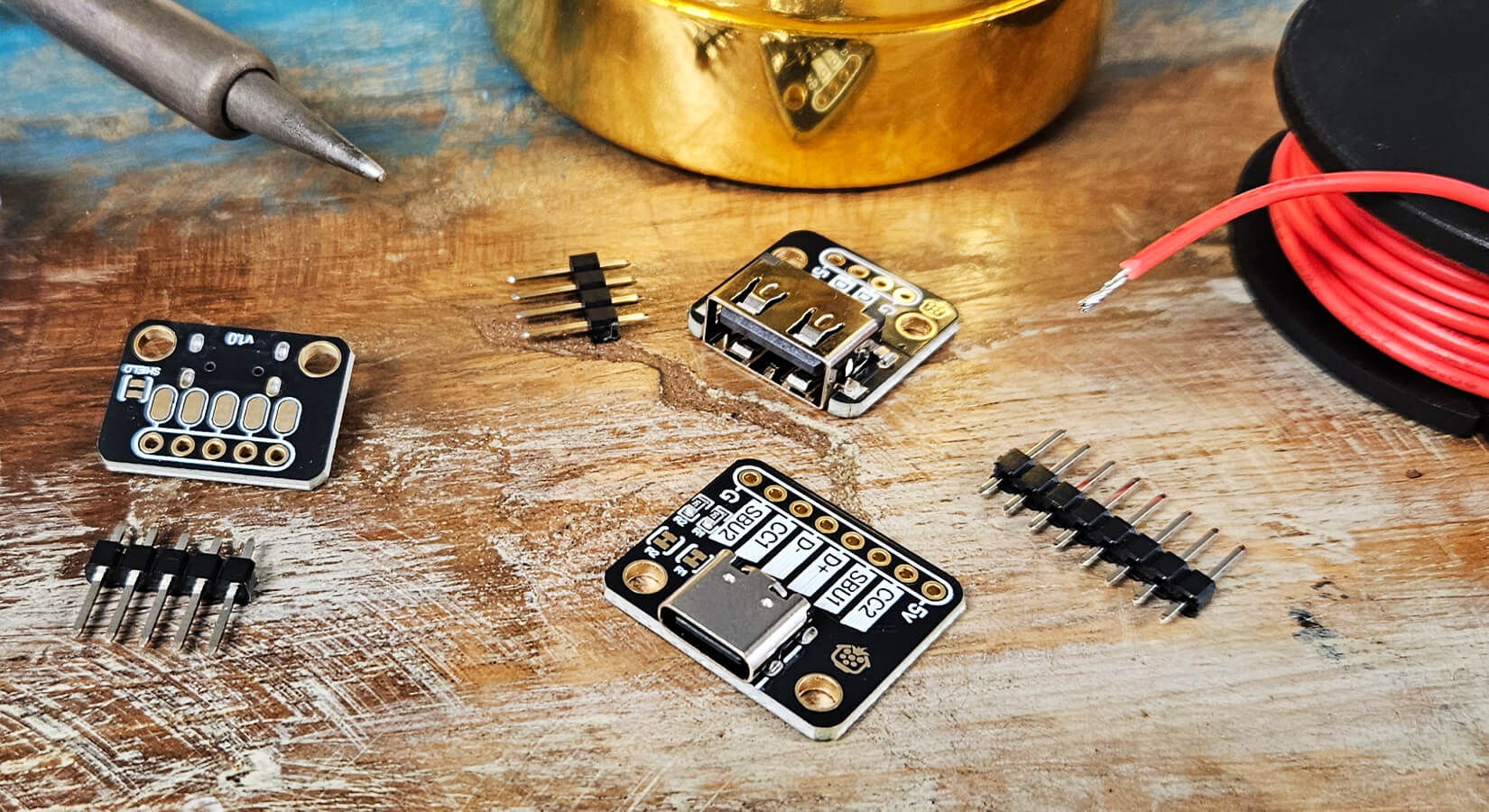
Header strip
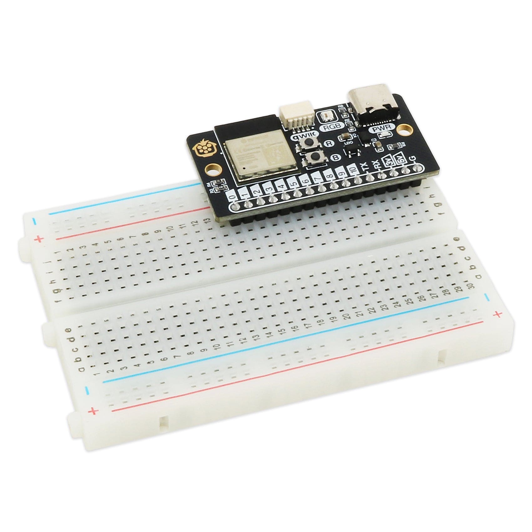
If you purchased an unsoldered board, a header strip is included in the package, which you can solder on for breadboard usage if that's your intended use.

You can also fit compact 2.54mm terminal blocks if you prefer, an example of which can be seen in the image below (note that two blocks won't fit next to each other perfectly. We're using a 10-way block here to use specific pins):

We also offer a pre-soldered version that comes with the male headers assembled - ideal and intended for breadboard usage.
Underside pads
If you plan to solder wires directly to the board, we recommend soldering wires directly to the flat, oval underside pads. They're a lot easier to work with and rework later on vs soldering into the pad holes.

Mounting holes
A quick note on mounting - the board features two M2.5 mounting holes, giving you an option to secure the board inside an enclosure or to a panel.
We stock M2.5 fixings in the store if you need any, including affordable nylon standoff packs and screws/nuts.

Boot/programming mode
If you're using the Baguette C3 for the first time or switching platforms, you may need to put the board into programming mode. This can be achieved by holding the BOOT button down during power-on (connecting the USB-C cable).
However, the easiest way to achieve this (and minimise wear and tear on the USB connector) is to hold down the BOOT button and then press the RESET button while still keeping the BOOT button held down.
After pressing RESET, you can then release the boot button, and the board should now be in programming mode. This process should be the same regardless of your host computer's operating system.
Programming the Baguette C3
This section will cover how to program your Baguette C3 using popular options for ESP-based boards - click a link below to jump to that section:
- Arduino
- ESPHome via Home Assistant
- MicroPython
- CircuitPython (coming soon!)
We won't be covering generic basics such as "how to install the Arduino IDE" or similar topics that are not specific to the Baguette C3, as these are already well-documented.
All examples and screenshots in this guide are from a Windows environment.
Other platforms - If you would like to see examples for other platforms, please add a comment at the end of this article.
Arduino IDE
The Baguette C3 uses an ESP32-C3 module, which is supported from the Arduino board package 2.0 and later, so we are focusing the guide on at least version 2.0. The screenshots below may look different as new versions are released, but the process should remain fairly consistent.
Install the software
The first step is to ensure you have the Arduino IDE installed and ready to go - you can download the software from Arduino here.
Board manager definition
Once installed, we need to ensure that we have the ESP32 defined in the board manager.
Navigate to Tools -> Board -> Board Manager - this will show a sidebar on the left-hand side, and if we type "ESP32" into the search, we can then select to install the “esp32 by Espressif Systems”:

Once this is added, you will now see a new 'esp32' menu when you go to Tools -> Board. We need to select ESP32 -> ESP32C3 Dev Module, as per the screenshot below:

Serial configuration
We now need to make a change so that we can get serial output onto the console for debugging.
Since we’ve selected the “ESP32C3 Dev Module”, we will now have more options under tools. We need to change the option “USB CDC On Boot:” to enabled, like this:

This setting allows the USB port to also be used for a serial console. This is needed as there is no discrete USB-Serial chip, as it’s built into the ESP32-C3 line of chips.
Port selection
Lastly, we need to confirm the correct port is selected under Tools -> Port. The ports listed, and port number, will depend on your platform and how many other devices you have connected; however, you may find that your Baguette shows up as an 'ESP32 Family device'.
Sometimes other devices will show up as COM ports, which can be confusing. The best way to figure out which one is your Baguette C3 is to disconnect it and see which port disappears from the list (then reconnect it).
Important: Disconnect any other development boards to avoid erasing another board!

We are now at a point where we can use our board with the Arduino IDE!
Onboard RGB LED (Addressable WS2812C)
We are going to be using the Neopixel example from Adafruit, who have created a great library that does a lot of the heavy lifting for us.
In the Arduino IDE, we need to go to Sketch -> include library -> Manage Libraries, like this:

Similar to the board manager, it will bring up a side pane where we can search for “Adafruit neopixel”:
![]()
Once the library has been installed, we can open one of the newly installed examples by going to File -> Examples -> Adafruit Neopixel -> Simple example.
We have to make two changes to the file to make it work with our Baguette C3 to indicate that our RGB LED is connected on pin 8, and we have a single pixel:
// Which pin on the Arduino is connected to the NeoPixels?
#define PIN        8 // On Trinket or Gemma, suggest changing this to 1

// How many NeoPixels are attached to the Arduino?
#define NUMPIXELS 1 // Popular NeoPixel ring size
To explain the example, we have three main commands for controlling the LED.
pixels.clear();
This command sets the pixel colours to off.
pixels.setPixelColor(i, pixels.Color(0, 150, 0));
Here we can set the desired colour of the LED. The three supplied numbers are in an RGB (Red, Green and Blue) format and can range from 0 (off) to 255 (full brightness). So the above line will set the colour to be green at just above half brightness.
pixels.show();
Before we can see the colour, we have to include pixels.show to send the data to the LED.
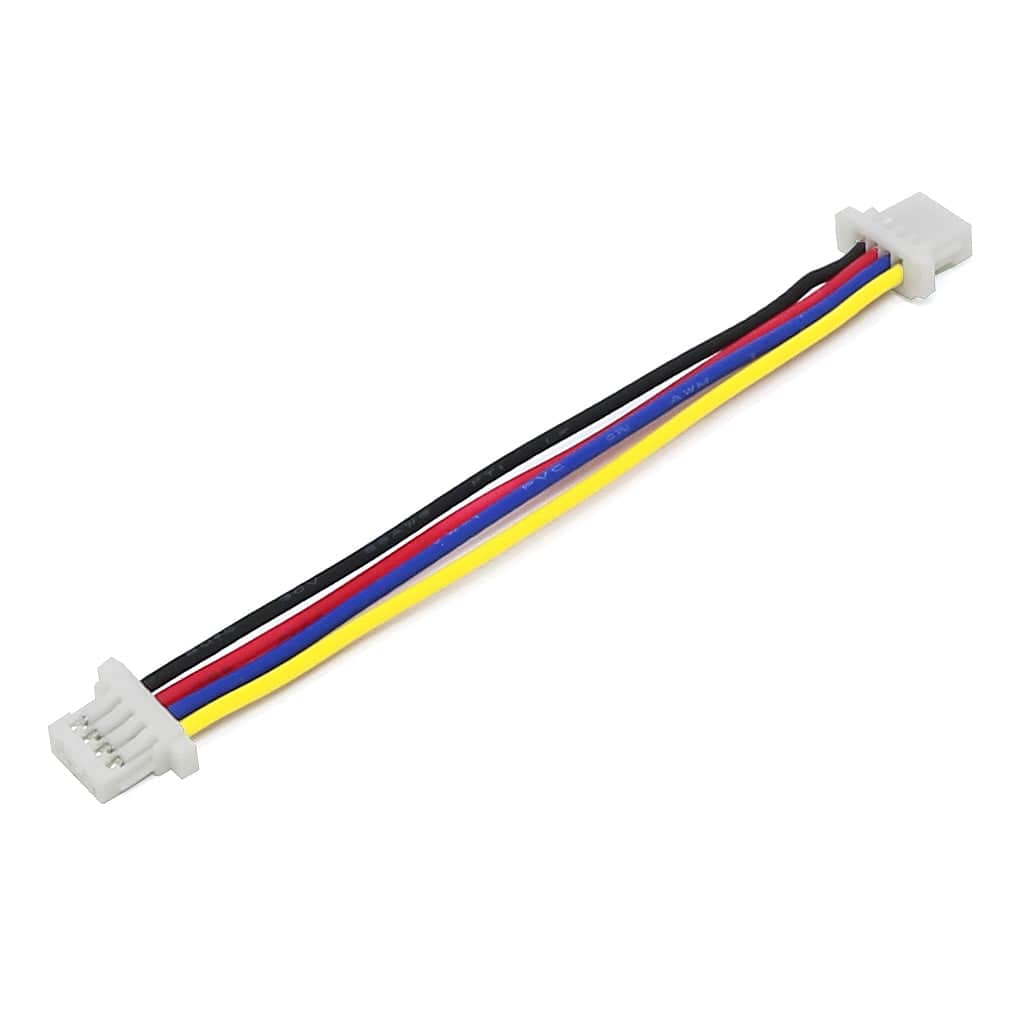
Qwiic Port / I2C
The Baguette C3 includes a Qwiic port for connecting 3.3V Qwiic sensors and devices. The Qwiic port uses GPIO5 for SDA and GPIO6 for SCL - both of which are available from the main header - allowing you to manually connect non-Qwiic I2C devices.
To show these pins, we are going to use the simple I2C scanner example available from randomnerd tutorials. We're going to use their code example, but we need to tweak it to work with our board first.
Start by adding our I2C pin definitions as new lines (after the #include line is good):
#define I2C_SDA 5
#define I2C_SCL 6
Then we need to specify the pins by modifying the existing Wire.begin(): line to the following:
Wire.begin(I2C_SDA, I2C_SCL);
With those in place, if you have a device plugged into the Qwiic port, or into the dedicated header pins, when you run your code, the Serial Monitor should now display something similar to this:
I2C Scanner
Scanning...
I2C device found at address 0x77
done
The address shown will differ depending on the device you have connected (many Qwiic devices have a fixed address and are sometimes printed on the PCB).
If you see no addresses, check your wiring and make sure you have 'USB CDC on boot enabled' in the IDE (which we set earlier).
ESPHome via Home Assistant
Working with ESPHome can be a little more intricate, but also a lot simpler in some ways.
The examples below are using version 2025.8.3. As new versions are released, things may change, look different or just plain ol' break! Let us know in the comments if you experience any issues.
For our example, we are going to add the board from within the Home Assistant ESPHome addon. We're assuming that you already have ESPHome running on your Home Assistant host device, if not, you can follow the instructions here.
Add Baguette C3 to ESPHome
To begin, we navigate to the ESPHome Add-on page and click “New Device” (bottom right corner currently):

You will be asked for a new name for your device. For our example, we'll name the board “baguette-c3”:

At this point, we'll be asked to connect the Baguette C3 board to the computer we are running the configuration from, and select “Connect”:

We then need to select the serial port, which will show up as USB JTAG/Serial or similar, depending on the platform you are using.

After clicking connect, it will then show “Preparing Installation”. This can take some time.
If you receive a warning that the operation was successful but the board could not be reconnected, pressing the RESET button usually resumes communication.

Once the process has finished, you will now have a new entry for the board in your ESPHome dashboard within Home Assistant:

From here, you can click edit and view the default YAML config. It’s recommended to add it in this manner as the items, such as the api key and OTA password, are unique for your setup.
Board definition
The board definition we require is installed by default; however, we need to specify the board by configuring the following in our example:
esp32:
  board: esp32-c3-devkitm-1
  framework:
    type: esp-idf
We also need to set the web server to be active so we can see our options and interact with the board. This can be achieved by inserting the following into our config:
web_server:
  port: 80
Onboard RGB LED (Addressable WS2812C)
To use the onboard RGB LED, we need to define which pin we are using and the number of LEDs, like this:
light:
  - platform: esp32_rmt_led_strip
    rmt_symbols: 96
    chipset: ws2812
    rgb_order: GRB
    is_rgbw: False
    pin: GPIO08
    num_leds: 1
    name: "Neopixel LED"
    id: leds
    color_correct: [80%, 80%, 80%]
    default_transition_length: 2s
With this configuration, we can visit the board in ESPHome, which will give us the following webpage, where we can see the RGB LED state and toggle it as well as set the brightness level:
![]()
Qwiic Port / I2C
The Baguette C3 includes a Qwiic port for connecting 3.3V Qwiic sensors and devices. The Qwiic port uses GPIO5 for SDA and GPIO6 for SCL - both of which are available from the main header - allowing you to manually connect non-Qwiic I2C devices.
We are going to configure the pins required and then run a scan for connected I2C devices. We need to include the following config:
Web_server:
  port: 80

i2c:
    sda: 5
    scl: 6
    scan: True
It's as simple as that, and if you now visit the board in ESPHome or bring up the logs, you will see output similar to below (but with the address of your device):
[16:54:31][C][i2c.idf:081]: I2C Bus:
[16:54:31][C][i2c.idf:082]: SDA Pin: GPIO5
[16:54:31][C][i2c.idf:082]: SCL Pin: GPIO6
[16:54:31][C][i2c.idf:102]: Results from bus scan:
[16:54:31][C][i2c.idf:108]: Found device at address 0x77
MicroPython
As usual, we'll be using Thonny as our IDE for MicroPython. Not the most fashionable, but it's widely used by beginners and experienced alike.
Install the software
The first step is to ensure you have Thonny installed and ready to go - you can download Thonny here. Setup is straightforward and well-documented.
Install Thonny, open the program, then move on to the next step once you're ready.
Install MicroPython on the Baguette C3
Connect your Baguette C3 to your PC via USB-C, then put your board into boot/programming mode as we showed you earlier.
In Thonny, click this section at the bottom-right corner of the interface, then select 'Configure Interpreter'.

You now need to select 'MicroPython (ESP32)' in the first drop-down box, automatic detection in the second box (usually defaults to this):

WAIT! Don't click 'OK' yet! You now need to select the 'Install or update MicroPython (esptool)' link:

This will bring up another window where you need to select the following options:
-
Target port: Usually, the 'USB JTAG' option
- If you see multiple options, come out, disconnect other devices, and try again.
- MicroPython family: ESP32-C3
- Variant: Espressif-ESP32-C3
- Version: Select the latest version (1.26.1 at the time of writing)

Now select 'Install' and Thonny will install the correct flavour of MicroPython to work with your Baguette C3.
You'll see a progress bar at the bottom-left of the window, which will eventually show 'Done!'. You can now close that window, then select 'OK' to close down the interpreter window, returning you to the main Thonny interface.
Your board should now be automatically selected and showing at the bottom-right of Thonny like this (if not, click on that text and select the correct port/ESP32 option):

Your Baguette C3 is now ready with MicroPython installed!
Onboard RGB LED (Addressable WS2812C)
A Neopixel library is already built into MicroPython for our use. Below you'll find some example code to try this out.
Paste the code below into Thonny, then select the little green triangle (run button) or Select Run > Run current script from the menu:
from machine import Pin
from time import sleep_ms

import machine, neopixel, time

np1 = neopixel.NeoPixel(machine.Pin(8), 1)

while True:
    np1.fill((255,0,0)) # set to red, full brightness
    np1.write()
    sleep_ms(500)
    np1.fill((0,0,255)) # set to blue, full brightness
    np1.write()
    sleep_ms(500)
As a quick breakdown of the main elements here, the following line defines that we have one neopixel on pin 8, which we are calling np1:
np1 = neopixel.NeoPixel(machine.Pin(8), 1)
The following line sets the neopixel to full brightness with blue:
np1.fill((0,0,255)) # set to blue, full brightnessAnd this line then instructs the neopixel to set the colour we have selected.:
np1.write()Qwiic Port / I2C
The Baguette C3 includes a Qwiic port for connecting 3.3V Qwiic sensors and devices. The Qwiic port uses GPIO5 for SDA and GPIO6 for SCL - both of which are available from the main header - allowing you to manually connect non-Qwiic I2C devices.
The code below will scan for connected I2C devices. This is a nice and simple, self-contained example. We set up the I2C pins that the Baguette C3 is using, then use the built-in i2c.scan() command, which will scan for any I2C devices and report their addresses:
from machine import Pin, I2C
import time

# Setup I2C on I2C0
i2c = I2C(0,
          scl=Pin(6),
          sda=Pin(5),
          freq=100000)

# Scan for devices
devices = i2c.scan()
if devices:
    print("I2C devices found:", [hex(d) for d in devices])
else:
    print("No I2C devices found.")
    raise SystemExit
Over to you!
This guide walks you through everything you need to start using your Baguette C3. Time to get making!
Share your projects with us – breadboard builds, embedded ideas or tidy soldering jobs – and we’ll repost our favourites for inspiration.
Need a hand? Just leave a comment and we’ll help out.

7 comments
The Pi Hut
@Peter Baxendale – A schematic will be added shortly.
Re the 5v pin, this feeds into the LDO input and also the onboard RGB-LED, this works down to 3.7v.
Re powering via a 3.7v battery (LiPo?), the LDO has a dropout of around 100mV at 100mA, but increases as the current is increased, so could be as high as 260mV at a 200mV difference. Depending on the draw the battery is going to work from about 4.2v down to 3.4v/3.5v.
The Pi Hut
@Daniel – We’ve updated the guide to show a full pinout including shared pins, and update the GPIO section wording to offer more detail here. A schematic will be added shortly. We’re working on having dedicated board definitions, including formally adding to CircuitPython as well.
@Daniel – We’ve updated the guide to show a full pinout including shared pins, and update the GPIO section wording to offer more detail here. A schematic will be added shortly. We’re working on having dedicated board definitions, including formally adding to CircuitPython as well.
Peter Baxendale
Any chance of a circuit diagram? I notice you say that to power the board from pins the 5V pin should be a regulated 5V. Does it supply something else as well as the regulator then? Or could I supply the board from a 3.7V battery via this pin (as I do, for example, for the little waveshare esp32 boards)? I’d have thought the on board LDO regulator would be ok with this…
Any chance of a circuit diagram? I notice you say that to power the board from pins the 5V pin should be a regulated 5V. Does it supply something else as well as the regulator then? Or could I supply the board from a 3.7V battery via this pin (as I do, for example, for the little waveshare esp32 boards)? I’d have thought the on board LDO regulator would be ok with this…
Daniel
Nice introduction. It would be good to include a full pinout description, noting which pins have special uses, are strapping pins, etc. I am particularly interested in which pins are used by hardware SPI.
I note that the pins_arduino.h for the ESP32C3 DevKit are NOT right for this board. There should really be a board definition specifically for the Baguette as it doesn’t seem to correspond to any standard C3 board.
Richard Sunderland
If possible it would be good to see a rust programming example. Bit niche perhaps, but would be appreciated.
If possible it would be good to see a rust programming example. Bit niche perhaps, but would be appreciated.
The Pi Hut
@Leon – Good spot, thanks for the comment! We’ve updated the article. Enjoy your Baguette C3 🥖
@Leon – Good spot, thanks for the comment! We’ve updated the article. Enjoy your Baguette C3 🥖
Leon Heller
In the Neopixel example this line should have ‘blue’ instead of ‘red’:
np1.fill((0,0,255)) # set to red, full brightness
np1.write()
In the Neopixel example this line should have ‘blue’ instead of ‘red’:
np1.fill((0,0,255)) # set to red, full brightness
np1.write()