How to assemble the Slice of Pi kit

First of all, solder the 26-pin header. You need to put the header on the bottom of the board, with the pins poking through to the top. Use a blob of blutack to hold the header in place then solder the pins from the front side. I recommend soldering the two pins on opposite corners (as below) first and then making sure that the header is on straight and at right angles. If it isn’t, just hold the header and reheat the solder to adjust it.

You will eventually end up with all 26 pins soldered. If you accidentally put too much solder on, use a solder sucker or solder braid to get rid of the excess. 
It’s now that you need to make some decisions. The board is very versatile and comes with several female headers that you can fix to the board. You do not need to solder these on, depending on what you want to use the board for. If you want to use the board with an XBee-style board, you’ll need to solder on the smaller headers. Place the headers onto the board and hold them in place with blutack. Solder them on the underside

If you want to use the board to breakout the GPIO pins to convenient headers then use the larger female headers, hold them in place using blutack and solder them on the underside of the board
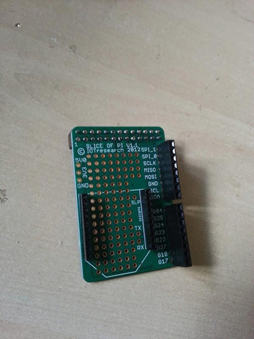
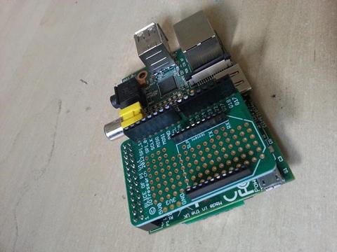
Once you’re finished, you can plug the board into your Raspberry Pi. Always do this while the Pi is turned off! You now have a great platform for doing some prototyping or just plugging things into the female headers! Do not solder onto the board while it is plugged into your Raspberry Pi. It’s just not very sensible! 
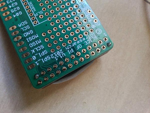
You will notice that there is a gap between the bottom of the board and the Raspberry Pi. This has advantages because it means it’s not covering the DSI port (the thin white port in the picture below) but also means that there is no support on the opposite side to which it is plugged in to the Raspberry Pi. Just be careful not to exert too much pressure on the board – you could end up damaging the GPIO pins if you do