Pololu CT220BMV-HS5 Contactless Current Sensor Carrier (±1.5mT/15G)
Price:
Sale price
£4.80
Stock:
Quantity:
Login / Signup
Cart
Your cart is empty


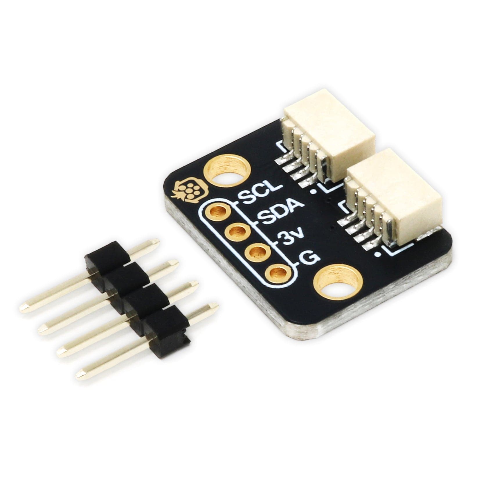
This board from Pololu is a simple carrier of Allegro’s CT220BMV-HS5 TMR-based, contactless current sensor, which measures the magnetic field of the current flowing through a nearby conductor without needing to be connected in series with the circuit. With calibration, its analog voltage output can be converted into an accurate current measurement.
We are offering these breakout boards with support from Allegro Microsystems as an easy way to use or evaluate their CT220 tunnelling magnetoresistance (TMR), contactless current sensors; we therefore recommend careful reading of the CT220 datasheet before using this product..
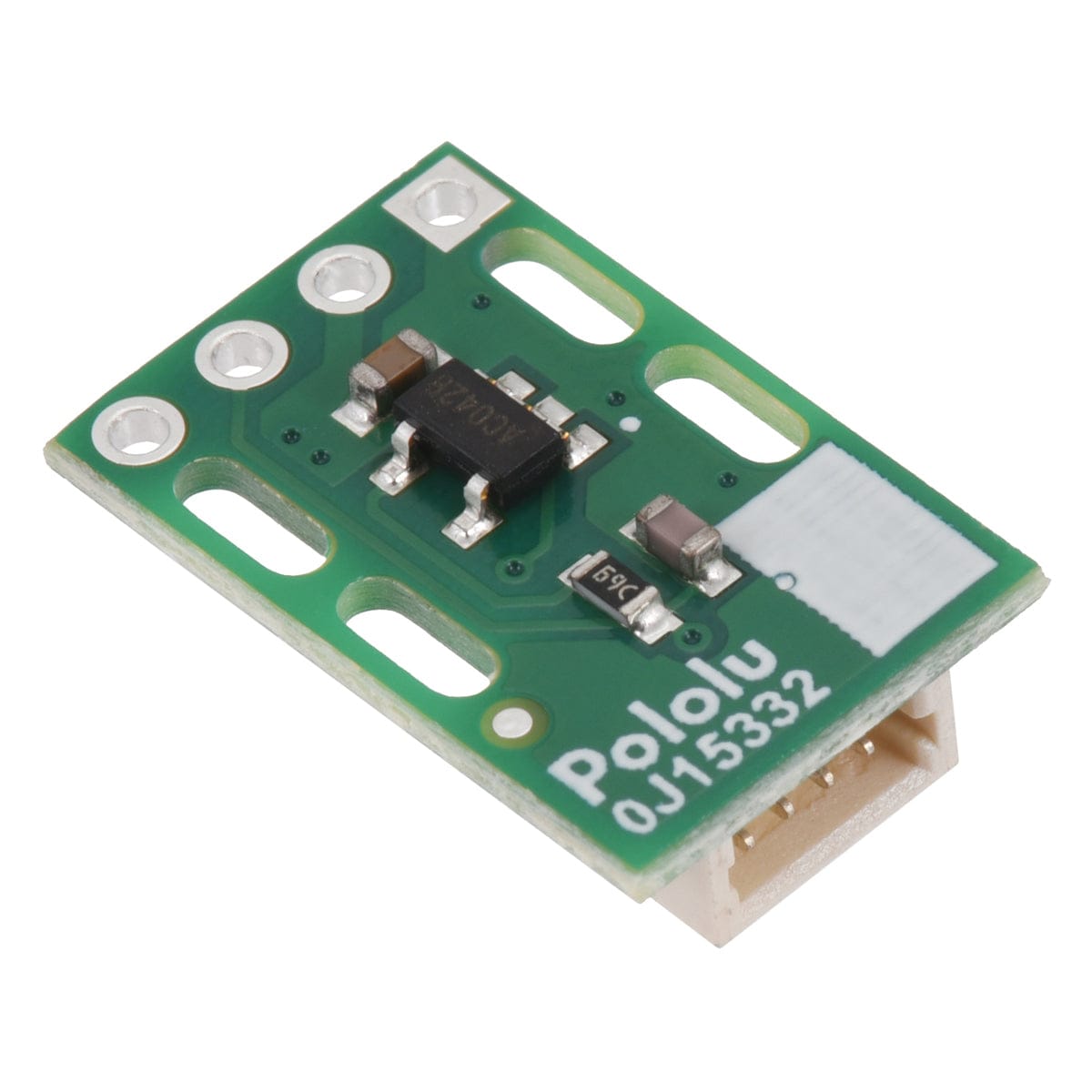
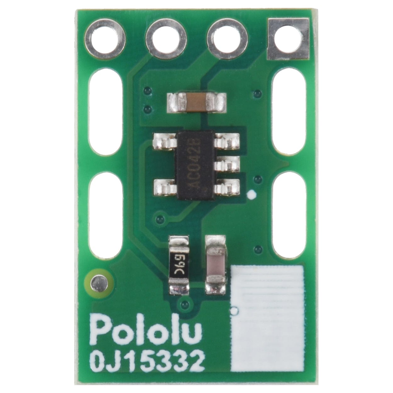
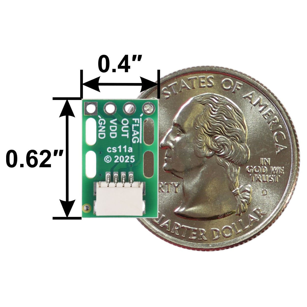
This version of the carrier board features the CT220BMV-HS5, which has a magnetic field range of ±1.5 mT (±15 G). Its output sensitivity is 1500 mV/mT when VDD is 5 V (or 990 mV/mT when VDD is 3.3 V). This version can be visually distinguished from the other versions by a marking that starts with AC printed on the sensor IC, as shown in the images (the silkscreen also has a blank white box that can be used for adding customised identifying markings).
The sensor’s current range and current sensitivity depend on its distance from the conductor, along with other parameters like the conductor’s geometry and angle relative to the board. When the board is tied to a round wire as pictured below, the overall diameter of the wire (with insulation) will be the main factor, and these graphs can help you estimate the sensor’s range and sensitivity for wires of different thicknesses. However, you should calibrate the sensor in your particular setup for best results (see Converting the sensor output into a current reading below).

The following list details some of the sensors’ key features:
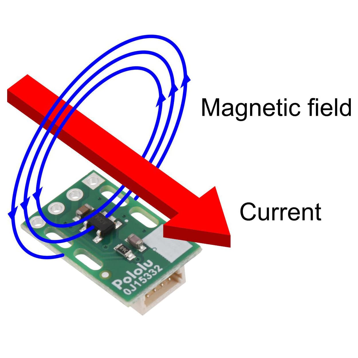
This CT220 carrier board is designed to measure a current running parallel to the long axis of the board, which generates a magnetic field forming concentric circles around the current conductor. Two pairs of slots along the sides of the board provide a good way to attach the board to a wire with small zip ties (cable ties) or similar fasteners.

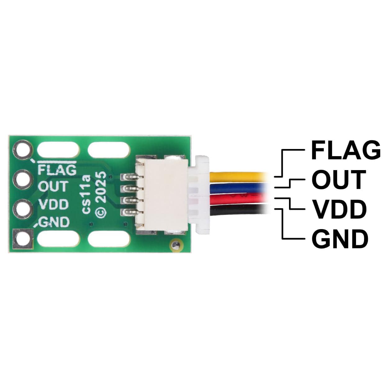
The sensor requires a supply voltage of 2.7 V to 5.5 V to be connected across VDD and GND. The sensor outputs a ratiometric analog voltage on OUT that is centred at VDD/2 and changes according to the magnetic field it senses.
When measuring current in a conductor on the same side of the board as the sensor (over the IC, such as with the sensor tied to a wire as shown above), current flowing in the direction of the red arrow in the picture above increases the output voltage, while current flowing in the opposite direction decreases the output voltage. If the conductor is instead on the opposite side of the board from the sensor (under the IC), these directions are flipped.
The FLAG pin is normally high and drives low when the magnetic field is above 90% or below 10% of the full field range.
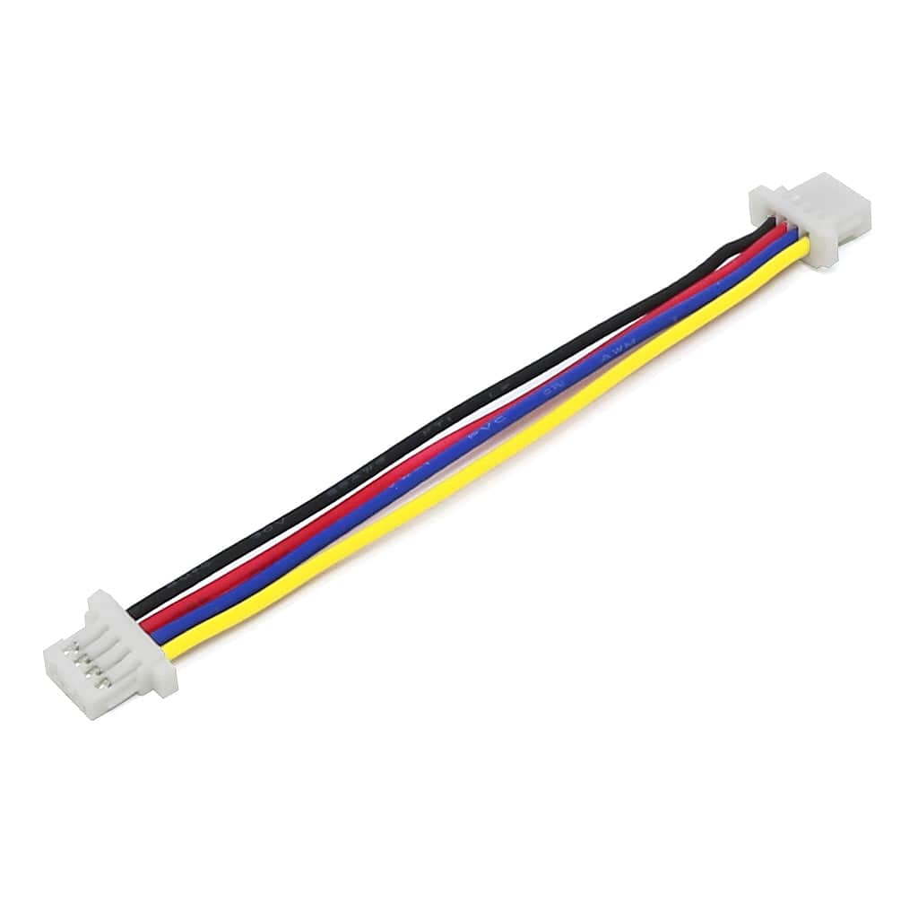
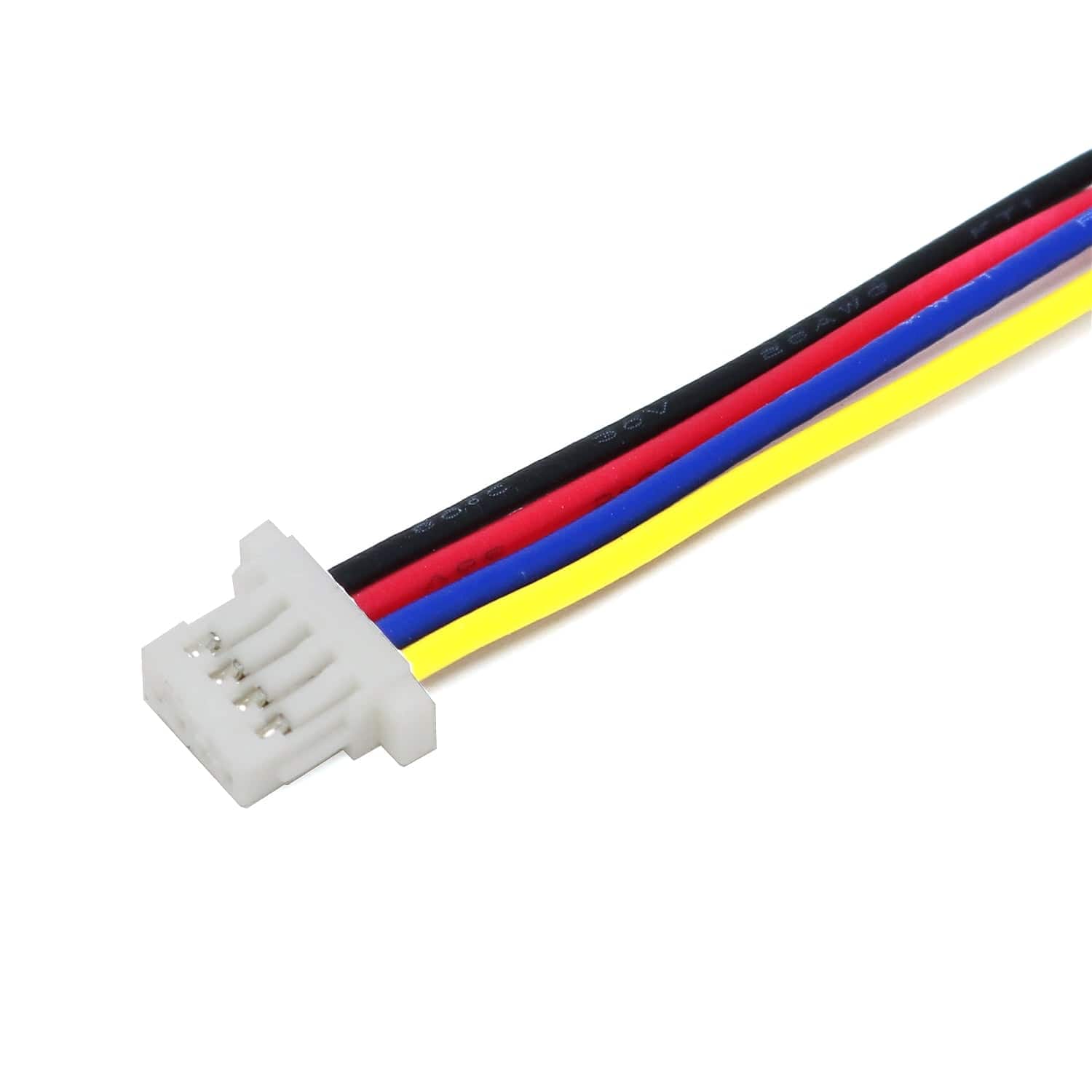
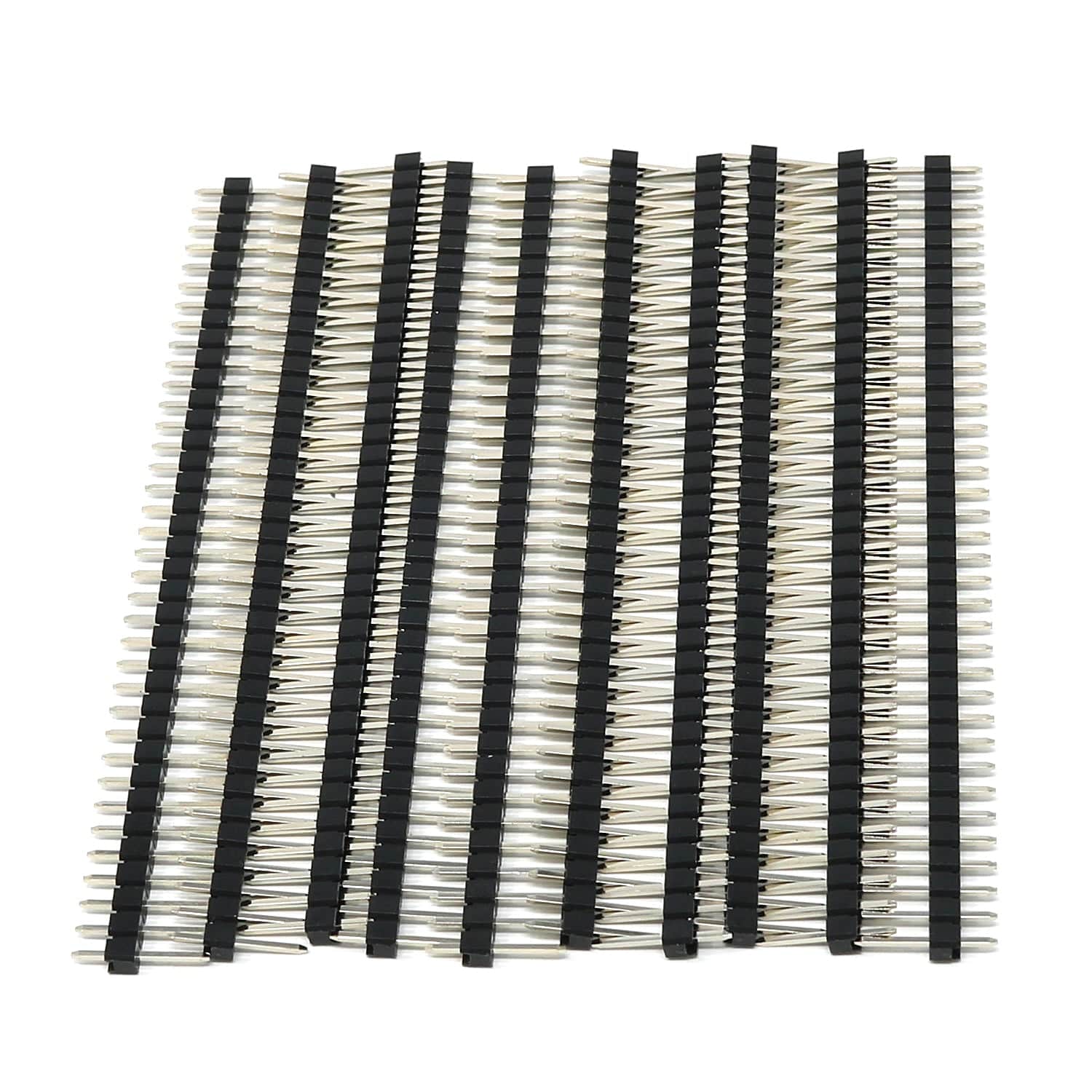
These connections can be made through the board’s JST SH-style 4-pin connector, which works with our 4-pin JST SH-style cables, or with a set of through-holes that are spaced with a 0.1″ (2.54 mm) pitch and compatible with 0.1″ male headers and solderless breadboards.

To get accurate current readings from the CT220, it is necessary to calibrate it in your application setup. A simple way to do this involves the following two steps:
Then, given a voltage VOUT measured from the sensor, you can calculate the corresponding current with the gain a and offset b:
To illustrate this with an example, let’s say you measure your sensor with no current flowing in the wire and get 2.5 V. Next, you put 10 A through your wire and measure the sensor voltage again, this time getting 2.8 V. That means the output voltage changed by 0.3 V for 10 A, so the sensitivity is 0.03 V/A, or 30 mV per A.
Note: For better accuracy in bidirectional current applications, Allegro recommends a slightly more thorough calibration procedure that involves applying a known current in both directions; see the CT220 datasheet for details.
| Size | 0.4″ × 0.62″ × 0.2″ |
| Weight | 0.4 g |
| Magnetic field sensitivity | 1500 mV/mT1 |
| Minimum logic voltage | 2.7 V |
| Maximum logic voltage | 5.5 V |
| Supply current | 1.2 mA2 |
| Magnetic field range | -1.5 mT to +1.5 mT |
| Current sensor | Allegro CT220BMV-HS5 |
| PCB dev codes | cs11a |
| Other PCB markings | 0J15332 |
Your payment information is processed securely. We do not store credit card details nor have access to your credit card information.