Login / Signup
Cart
Your cart is empty
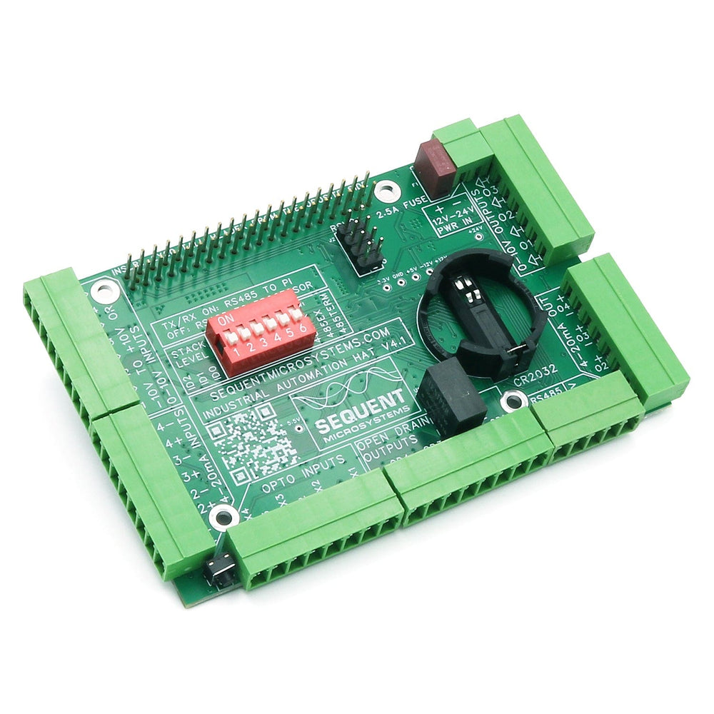
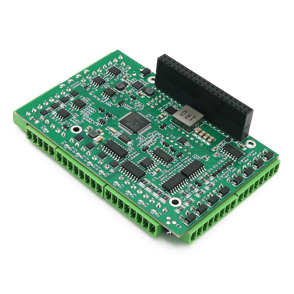
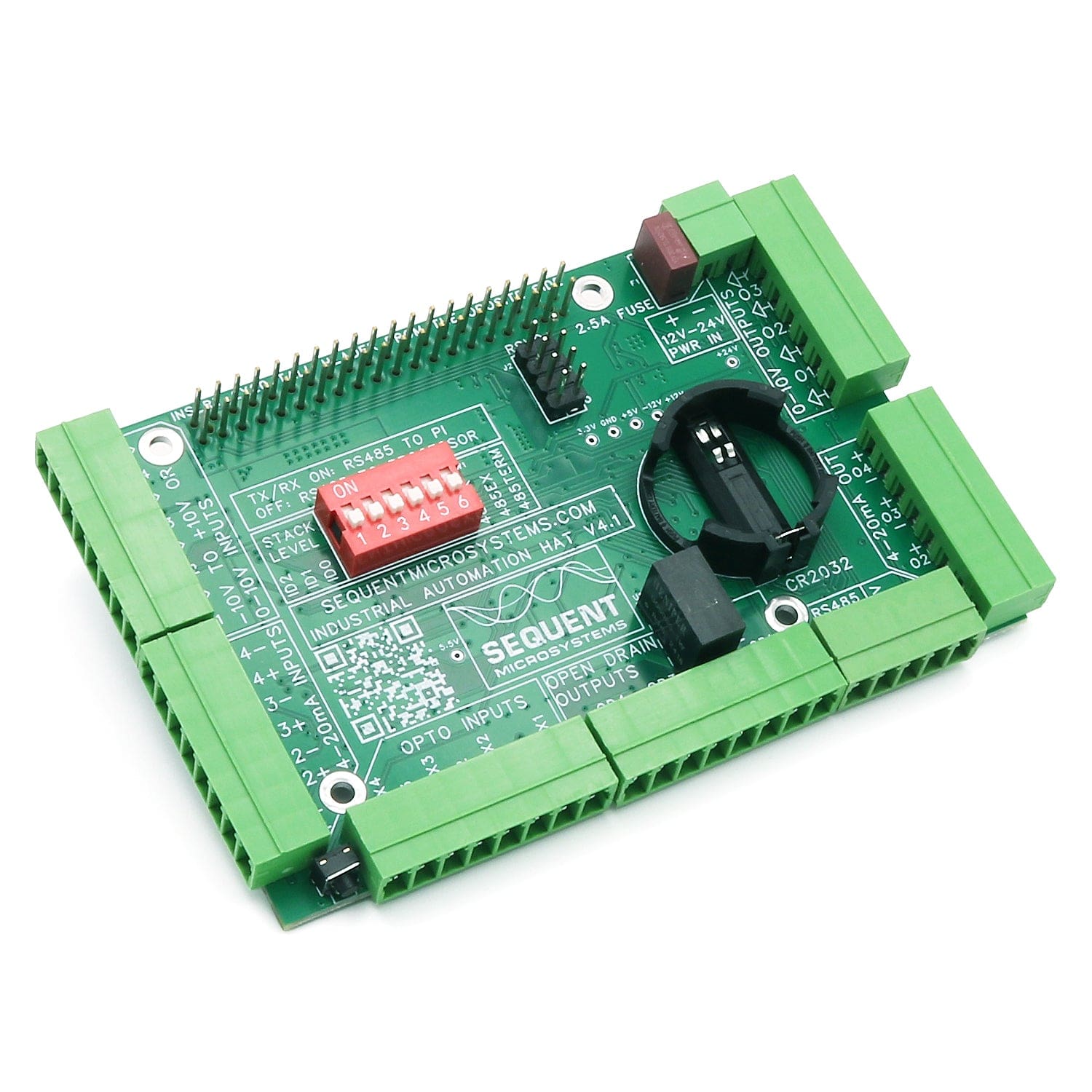
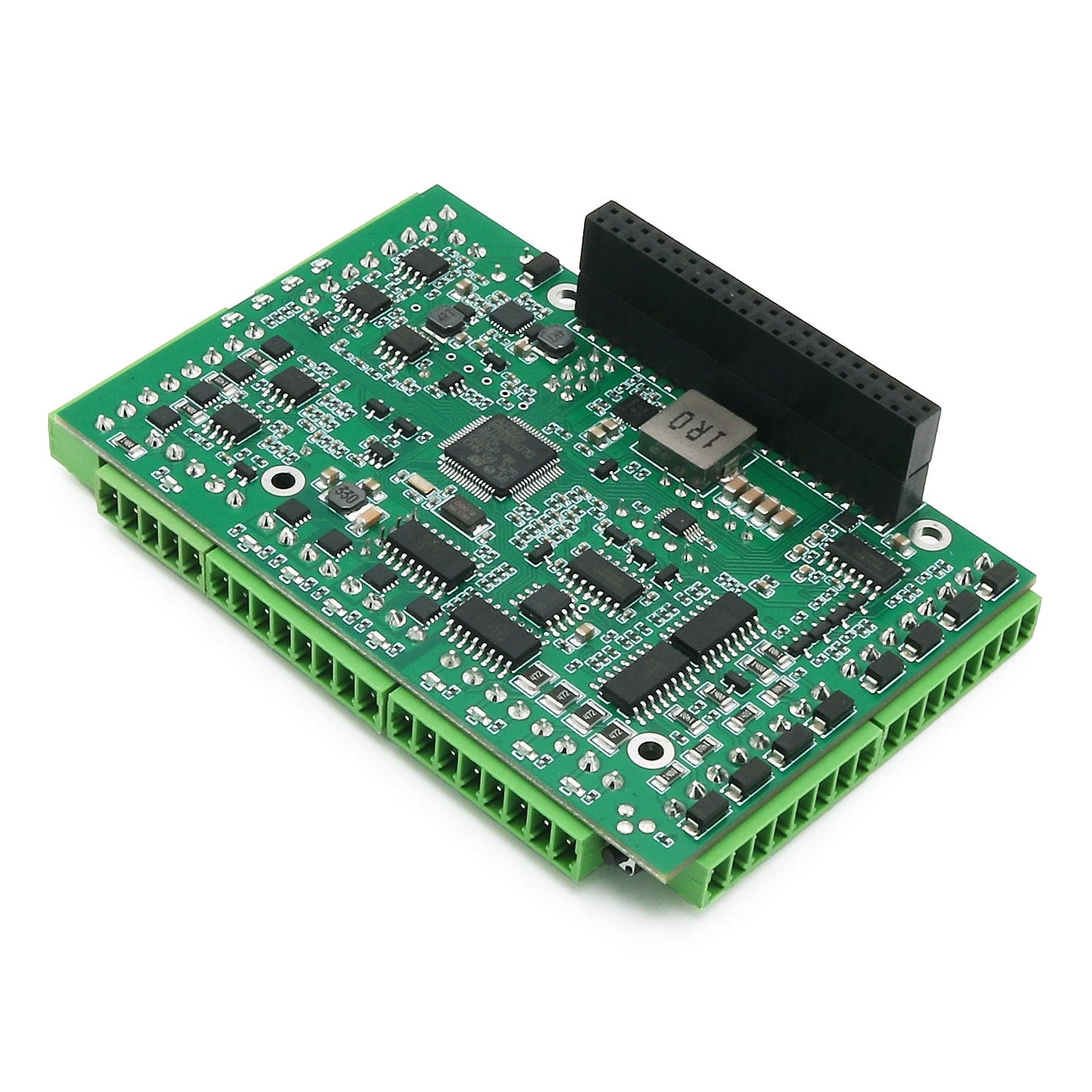
The Industrial Automation HAT for Raspberry Pi features a wide 12-30V power supply, optically isolated digital inputs and outputs, 16-bit 0-10V inputs, 14-bit 0-10V outputs, 4-20mA analog inputs and outputs, RS485 port, 1-Wire interface, hardware watchdog, and real-time clock with battery backup, making it ideal for industrial Raspberry Pi applications.
New version with major enhancements!
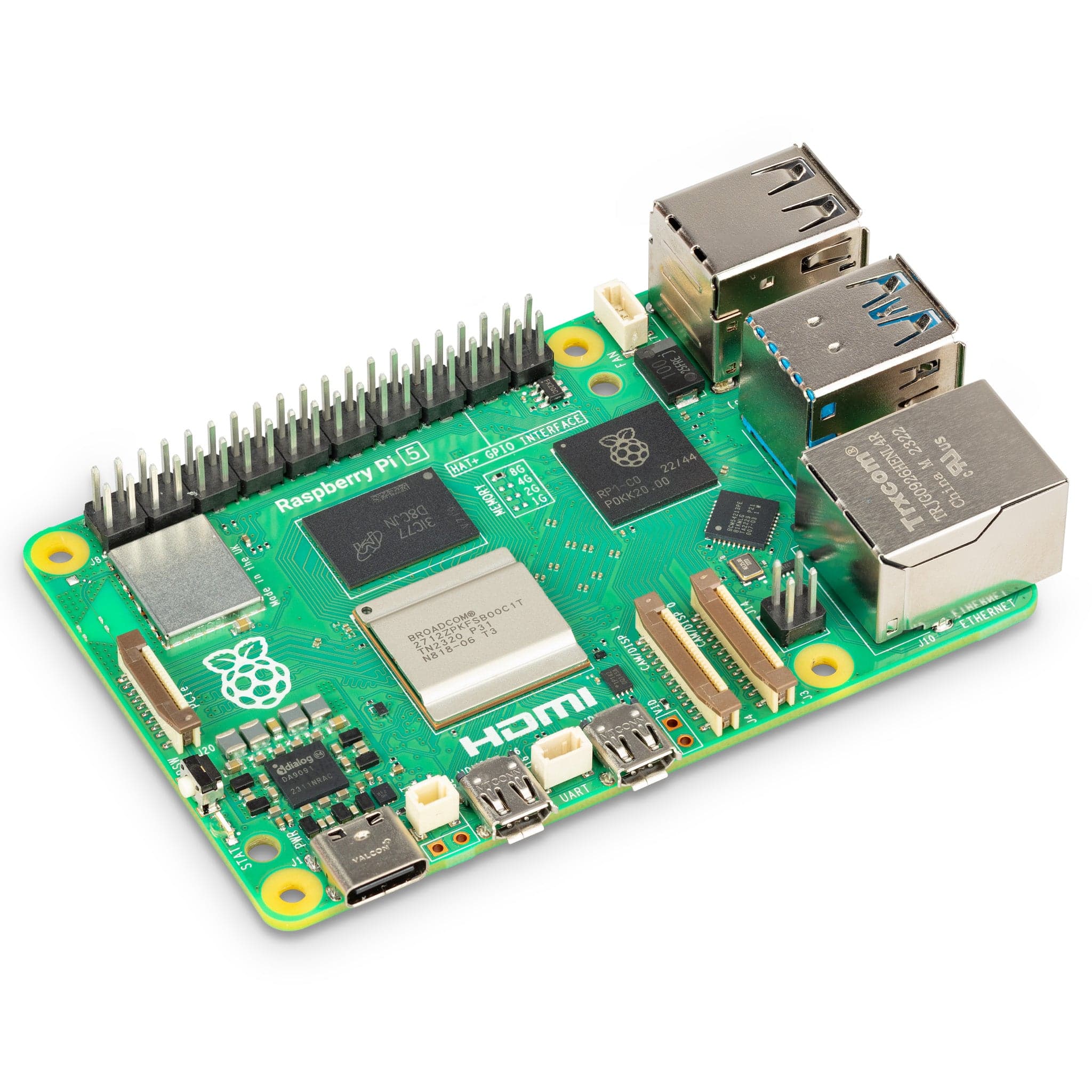
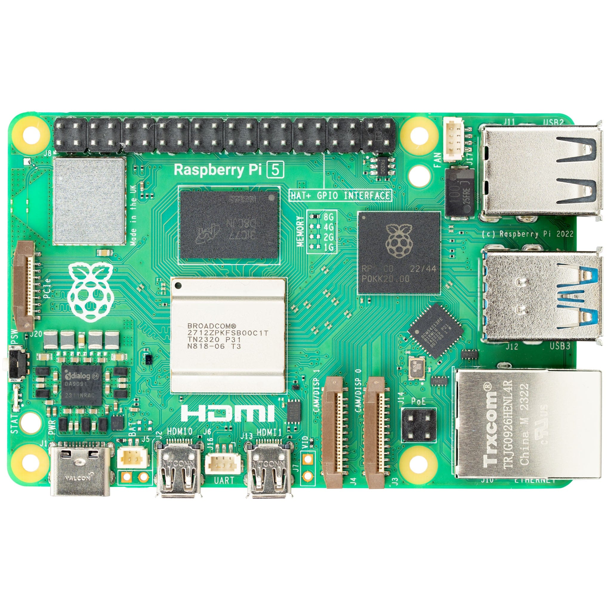
Note: Raspberry Pi not included
For any technical questions about this product please email support@sequentmicrosystems.com
You can write your control system in C, C++, PERL , or the language of your choice using the Command Line system or Python Drivers. Or you can implement everything in Node-Red and display it in the browser using the Node-Red node.
All the analog inputs and outputs are calibrated at the factory, but firmware commands permit the user to re-calibrate the board, or to calibrate it to better precision.
All inputs and outputs are calibrated in two points; select the two points as close to possible to the two ends of scale. To calibrate the inputs, you must provide analog signals. (Example: to calibrate 4-20mA inputs, you must provide a 4mA and 20mA current source).
To calibrate the outputs, you must issue a command to set the output to a desired value, measure the result and issue the calibration command to store the value.
The Industrial Automation card contains a built-in hardware watchdog which will guarantee that your mission-critical project will recover and continue running even if Raspberry Pi software hangs up. After power up the watchdog is disabled, and becomes active after it receives the first reset.
The default timeout is 120 seconds. Once activated, if it does not receive a subsequent reset from Raspberry Pi within 2 minutes, the watchdog cuts the power and restores it after 10 seconds.
Raspberry Pi needs to issue a reset command on the I2C port before the timer on the watchdog expires. The timer period after power up and the active timer period can be set from the command line. The number of resets is stored in flash and can be accessed or cleared from the command line. All the watchdog commands are described by the online help function.
The card contains a standard RS485 transceiver which can be accessed both by the local processor and by Raspberry Pi. The desired configuration is set from three bypass jumpers on configuration connector J3.
If jumpers are installed, Raspberry Pi can communicate with any device with an RS485 interface implementing any protocol it needs, Modbus, Profibus, PTZ control, etc. In this configuration the card is a passive bridge which implements only the hardware levels required by the RS485 protocol. To use this configuration, you need to tell the local processor to release control of the RS485 bus:
~$ megaind [0] rs485wr 0 0 0 0 0
If jumpers are removed, the card operates as MODBUS slave and implements the MODBUS RTU protocol. Any MODBUS master can access all the card's inputs, and set all the outputs using standard MODBUS commands. A detailed list of commands implemented can be found on GitHub.
In both configurations the local processor needs to be instructed to release (jumpers installed) or control (jumpers removed) the RS485 signals. See the command line online help for further information.
The card firmware can be updated in the field by running a command. The update is made with the latest firmware version located on our servers. More instructions about the process can be found on GitHub. Please make sure there is no process, like Node-Red or python scripts, that tries to access the card during the update process.
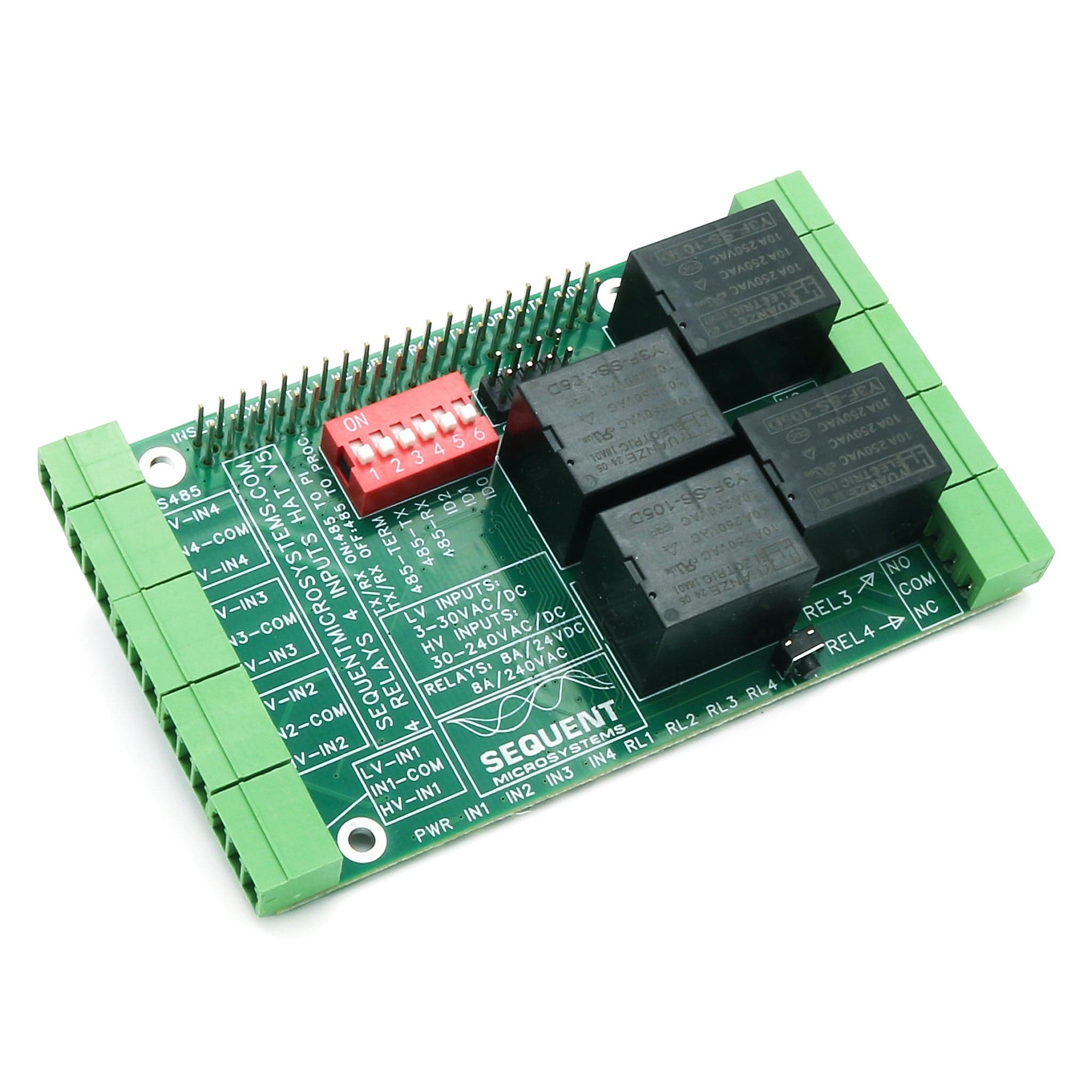
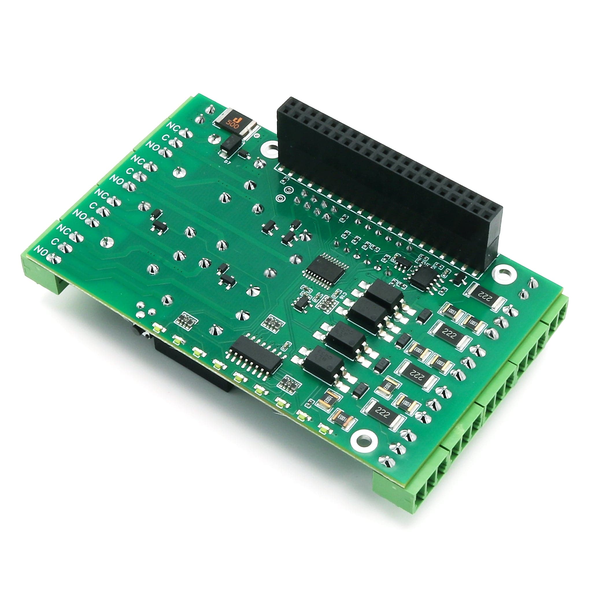
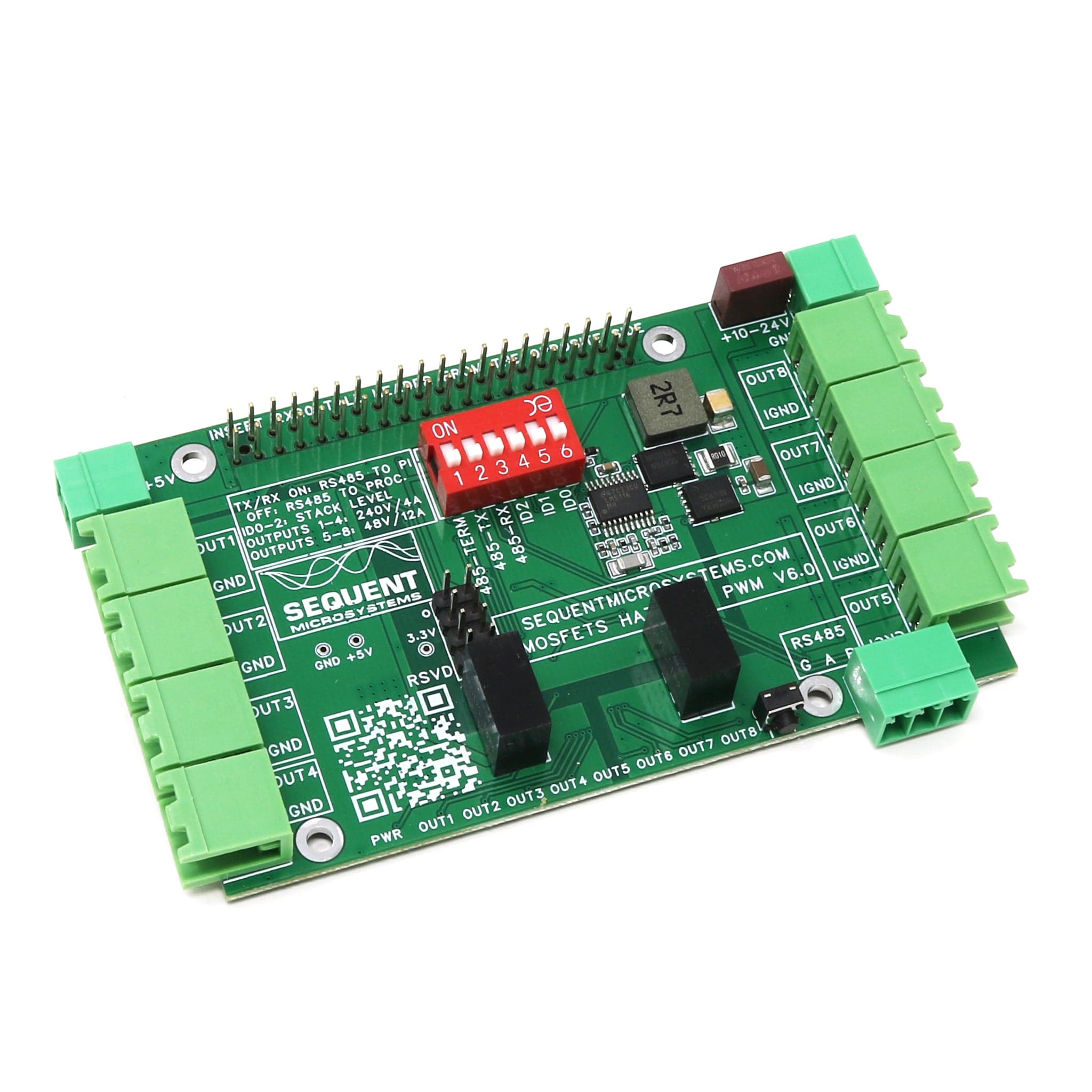
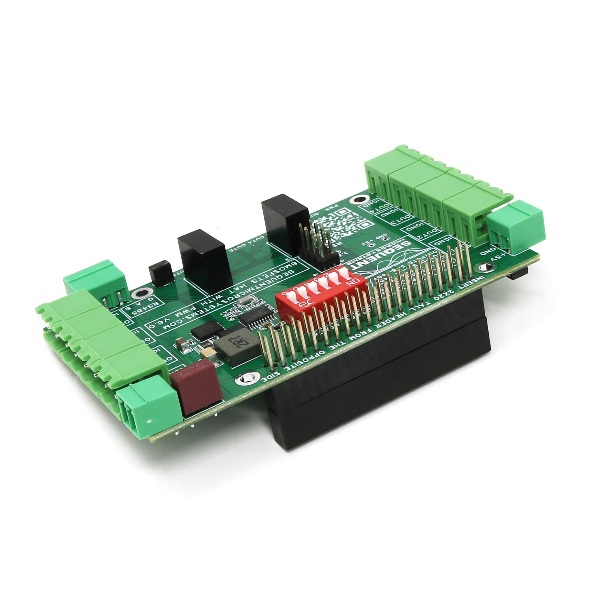
Heavy loads of up to 8A and 250VAC can be driven by adding one or more 4-RELAYS HATs. High DC loads of up to 10A and 250V, with fast response time and unlimited endurance can be driven by adding one or more 8-MOSFETS cards.
Connect the card to other Industrial Automation Systems using RS485/Modbus and 1-Wire communication ports. The RS485 can be driven either from the local processor through I2C commands, or directly from the Raspberry Pi using the dedicated pins on the GPIO connector, which are routed on the Industrial board to the RS485 driver.
NEW: 1-Wire Interface. Read DS18B20 Temperature sensors using the 1-Wire interface.
The Industrial Raspberry Pi Automation Cards share the I2C bus using only two of the Raspberry Pi’s GPIO pins to manage all eight cards. This feature leaves the remaining 24 GPIOs available for the user. It is compatible with all Raspberry Pi versions from Zero to 5 and has all the necessary I/Os for your Industrial Automation projects.
The Industrial Automation card needs an external 12 to 30VDC power supply and has to be powered from it's own pluggable connector. The card supplies 5V and up to 3A to the Raspberry Pi on the GPIO bus. A local 3.3V regulator powers the rest of the circuitry. The card needs 50mA to operate.
All the IO's are connected to heavy duty (8A), 3.5mm pitch pluggable connectors which make field wiring very convenient for installation and debugging.
Up to eight Industrial Automation cards can be stacked on your Raspberry Pi. Cards can be installed in any order. Each card is identified by jumpers you install to indicate the level in the stack.
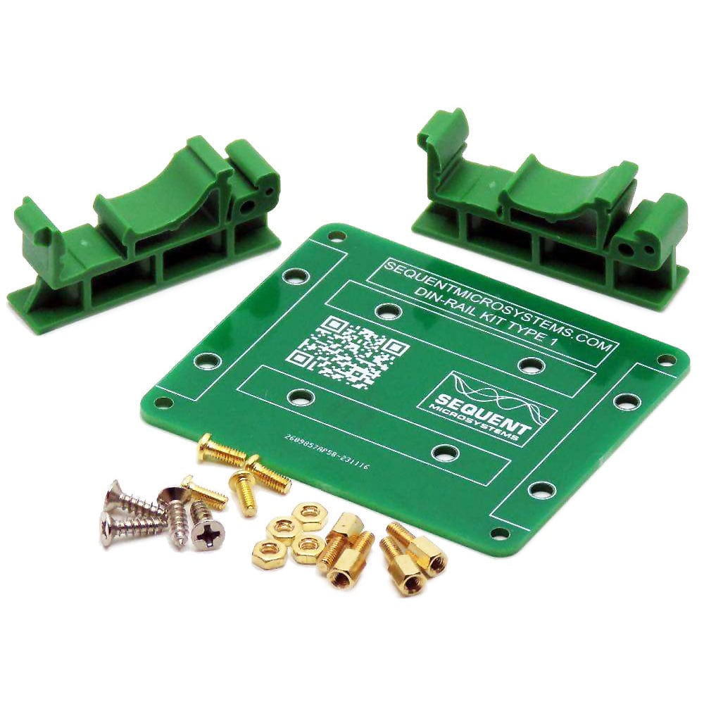
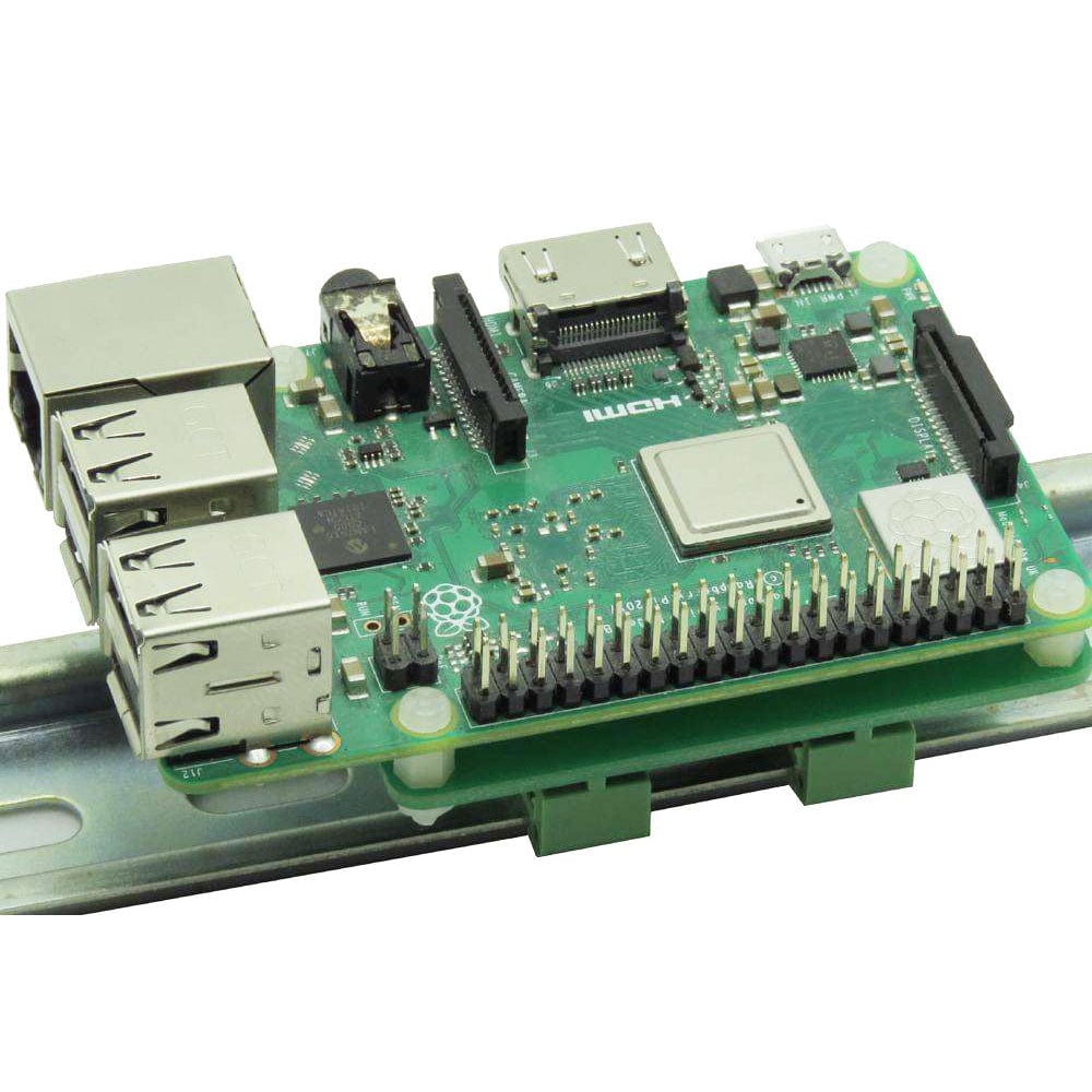
The Industrial Automation card can be installed parallel on a DIN-Rail using the DIN-Rail Kit Type 1, or perpendicular using the DIN-Rail Kit Type 2.
Raspberry Pi NOT included


