Challenger RP2040 UWB (DWM3000)
Price:
Sale price
£58.90
Stock:
Cart
Your cart is empty

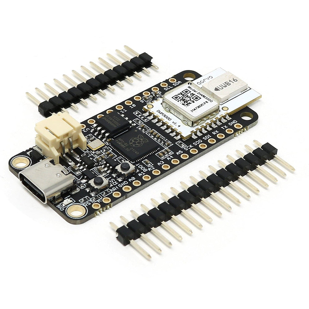
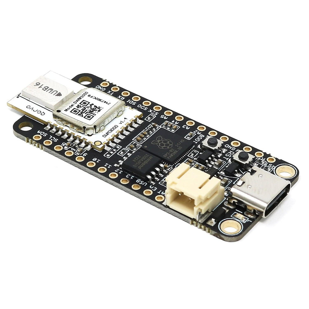
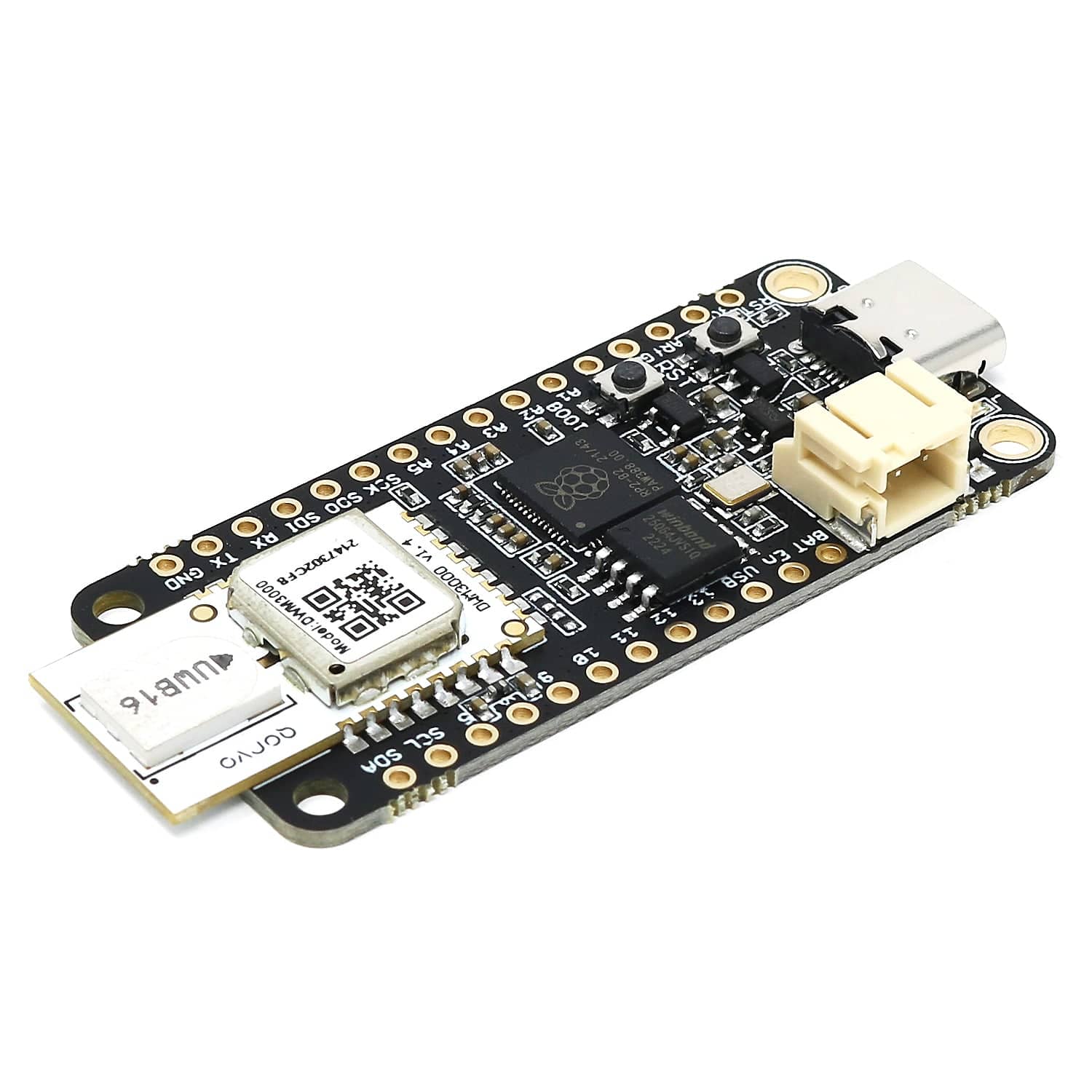
The Challenger UWB from iLabs is a small embedded computer equipped with a DWM3000 UWB module in the popular Adafruit Feather form factor. It's based on an RP2040 microcontroller chip from Raspberry Pi which is a dual-core Cortex M0 that can run on a clock up to 133MHz.
We wanted to start playing around with ultra-wide band (UWB) radios and positioning so we created a new Challenger board based on our proven RP2040 technology and added a DWM3000 UWB module. This module is compatible with Apple’s U1 chip and supports channels 5 (6.5GHz) and 9 (8GHz).
As usual, we paired the RP2040 microcontroller with 8MByte high-speed flash capable of supplying data up to the max speed. The flash memory can be used both to store instructions for the microcontroller as well as data in a file system and having a file system available makes it easy to store data in a structured and easy-to-program approach.
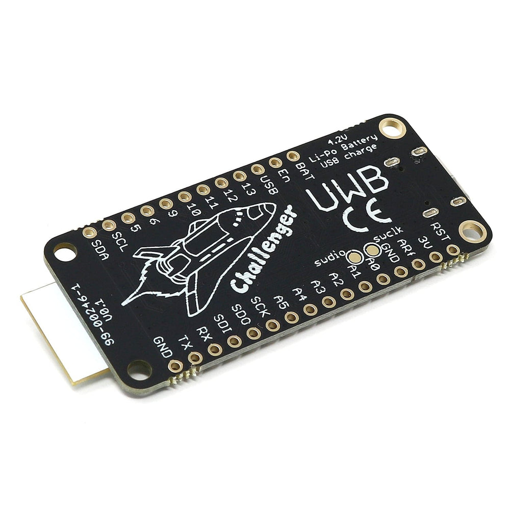
The board is based on a popular form factor called “Feather” which is created and maintained by an American company called Adafruit. The entire specification for the Feather format is available here. The size of the PCB for the module is 50.80mm x 22.86mm but the entire module is a little bit bigger as the Type C USB connector protrudes about 1 mm outside the board and on this particular board the antenna of the radio module also stick out about 4.4mm’s on the other side of the board.
The DWM3000 is an ultra-wideband (UWB) transceiver module developed by Qorvo Inc. It operates in the frequency range of 3.1 GHz to 10.6 GHz and has a maximum output power of 4 dBm. The module uses the IEEE 802.15.4a standard for UWB communication, which enables highly accurate ranging and positioning with an accuracy of up to 10 cm.
The DWM3000 module integrates a Qorvo DW3110 chip, which provides UWB communication capabilities. The module measures 21mm x 16mm x 2.5mm and has a power consumption of approximately 75mA during active mode and 1.5μA during sleep mode. It supports SPI and UART(Not supported on the Challenger board) interfaces for communication with external devices and has a built-in antenna for wireless communication.
It is designed for use in a variety of indoor positioning and communication applications, such as asset tracking, inventory management, and personnel tracking. It also features a small form factor and low power consumption, making it suitable for battery-powered devices.
Overall, the DWM3000 is a highly accurate UWB transceiver module designed for indoor positioning and communication applications that require high precision and low power consumption.
It is IEEE 802.15.4a and IEEE 802.15.4z BPRF mode compliant and allows location of objects to a precision of 10 cm. The module has worldwide UWB support through its operation on UWB channel 5 (6.5 GHz) and channel 9 (8 GHz). The module is also interoperable with the Apple U1 chip and is designed to be compliant to the FiRa™ PHY and MAC specifications enabling interoperability with other FiRa™ compliant devices.
Here’s a simple table with a few of the highlights of the module listed:
| UWB Channels | 5, 9 |
| Integrated Antenna | Yes |
| MCU | Customer supplied |
| MCU Flash (KB) | N/A |
| Bluetooth | No |
| Motion Sensor | None |
| Intended Applications | TWR Tag or Anchor, TDoA Tag or Anchor |
| Number of Tags | 100s (TWR), 1000s (TDoA) |
| Battery Life | Months (TWR), Years (TDoA) |
| Location Accuracy (cm) | < 15 (2D), < 30 (3D) |
| Voltage (V) | 2.4 to 3.6 |
| Package (mm) | 23xx x 13mm x 2.9mm |
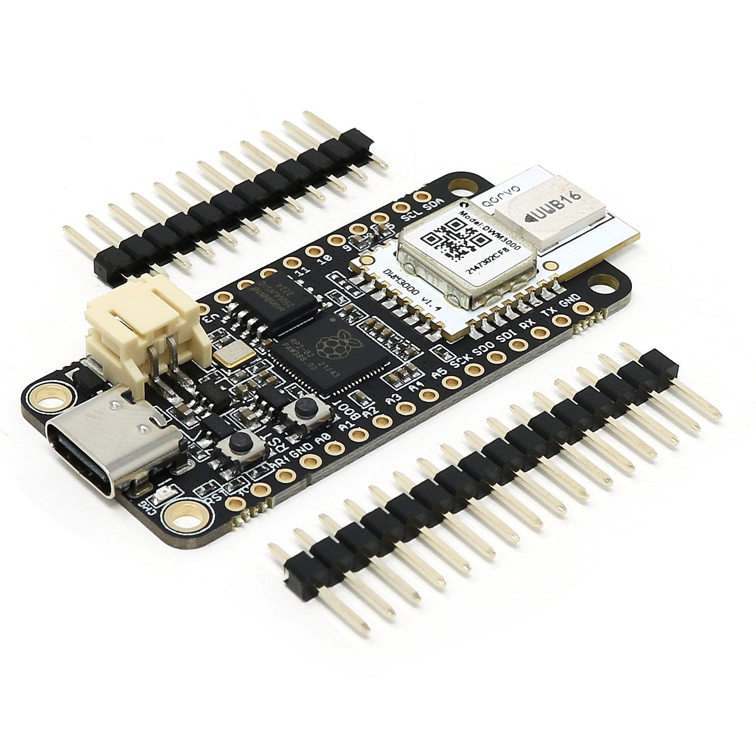
On each of the longer sides of the PCB there are holes intended for soldering pin header connectors. If you don’t want to use connectors for some reason you can also solder a wire directly into the hole, making a permanent connection to your external device. If you go this way please make sure that the wires are fixed in place, otherwise vibrations can cause the wire to brake at the soldering point.
On each side of the USB connector there is a small indicator LED placed. The LED which is marked CHG is the charge control indicator. This red LED will shine whenever the connected battery is being charged, and when the battery is fully charged the LED will turn off again. If you haven’t connected a battery to the board this LED will not come on at all.
On the other side of the USB connector there is a user programmable green LED. This LED is connected to pin D18 (BUILTIN_LED) and can easily be controlled by the user program.
The board can be powered from multiple sources. The most obvious way to run the board is by plugging it in to a USB cable and attach it to your computer. In this mode you can write software and test the board with all its functionality.
There is also a third way to supply the board. This way is more invasive and will disable the onboard 3.3V power regulator.
You will have to pull the EN header pin low and then supply your own 3.3V voltage on the 3.3V header pin. Please note that when disabling the onboard power regulator you will have to supply the 3.3V also when running the system on battery power.
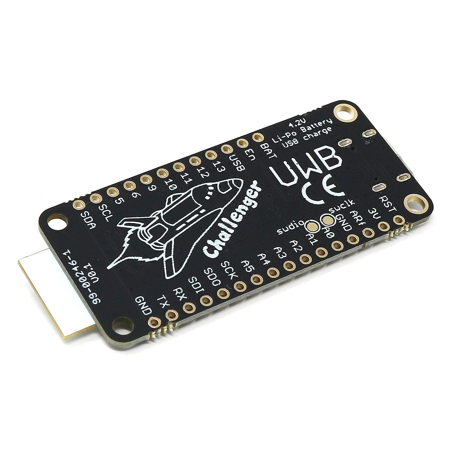
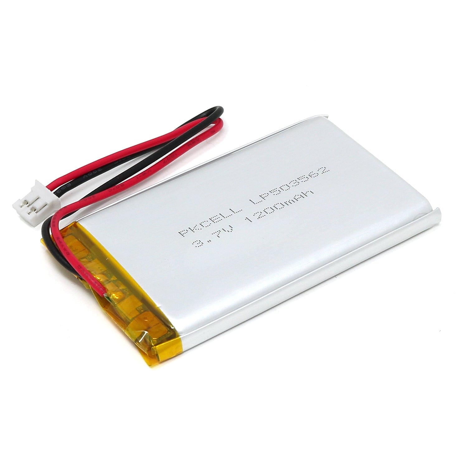
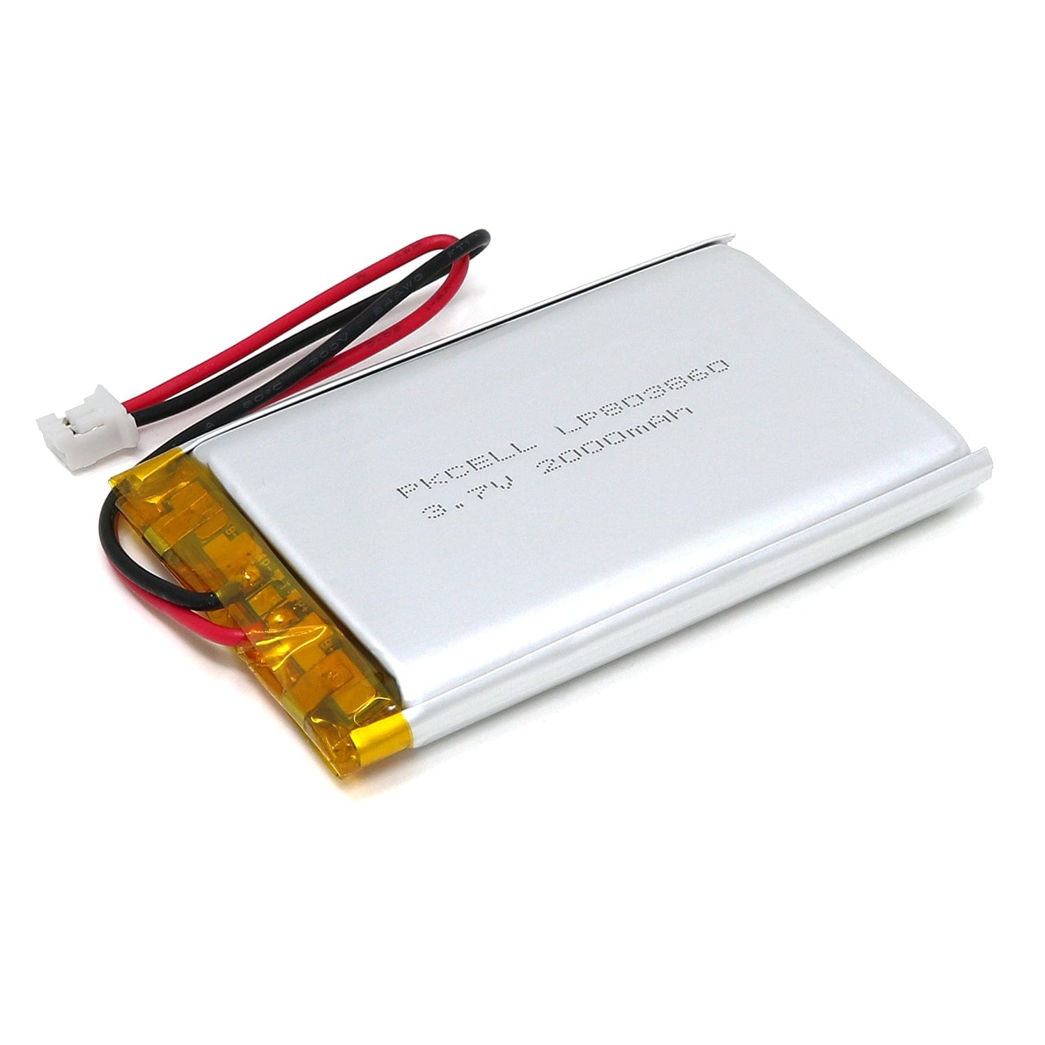
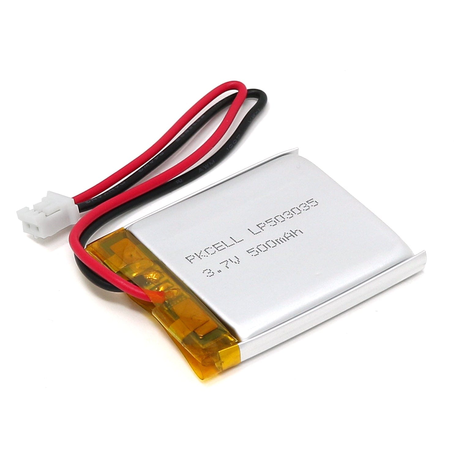
As described earlier the board can be powered from a LiPo battery. The battery can be connected using a standard 2.0mm JST connector through the battery connector on the right side of the board or off the battery is an integral part of the system that you are designing it is possible to connect the battery through the BAT pin instead.
Switching between the battery voltage and the applied USB voltage or external 5V is done seamlessly by the onboard circuitry.
Charging of the battery is done by either connecting a USB cable or by connecting a 5V power source to the header pin marked USB on the board. If you do this make sure you connect your voltage through a 1A schottky diode to avoid any excessive current draw in the system when the two levels are slightly different.
Please note that providing external charger circuitry could destroy the internal charger on the Challenger board.
| Description | Value | Comment |
| Board Size | 50,80 mm x 22,86 mm x 3,20 mm | USB protrudes by ~1mm |
| Microcontroller | RP2040 | 133MHz dual core Cortex M0 |
| SPI | One SPI channel configured | |
| I2C | One I2C channel configured | |
| UART | One UART channel configured | |
| Analog inputs | 4 analog input channels | |
| FLASH Memory | 8MByte 133 MHz | |
| SRAM Memory | 264KByte | Divided into 6 banks |
| USB 2.0 controller | Up to 12MBit/s full speed | Integrated USB 1.1 PHY |
| JST Battery connector | 2.0mm pitch | |
| On board LiPo charger | 500mA standard charge current | |
| Radio | DWM3000 | Ultra Wide Band Radio (UWB) |
Using the Arduino environment - iLabs have teamed up with Earle F. Philhower over at his Github page to provide Arduino support for our RP2040-based boards. You can follow the instructions on Earle’s GitHub page or you can check out our instructions here on how to install the package.
Library support for the UWB transceiver - iLabs has created an Arduino support library which can be found here.
CircuitPython - The Challenger RP2040 UWB board is compatible with Adafruit's CircuitPython, however to date there does not exist a support library in Python for the DWM3000 module.
The onboard microcontroller (RP2040) has a number of communication channels that have been routed out to the side (header connector) connectors.
The pin chart below shows the placement of all pins and their respective functions. When working in an Arduino environment (or Platform IO) use the blue pins when writing your code and when working with CircuitPython use the orange marked pin assignments.

The processor connects to the SD card via the second spi (SPI1) communication channel.
SPI1 Pin usage (Arduino pin names within parenthesis):
In addition to the SPI bus signals, a reset, a interrupt and a wakeup signal is also connected to the module, these are mapped to the pins as follows:
Note to Arduino users: The support library takes care of all the necessary configuration so you really don’t need to worry about the pins.
Your payment information is processed securely. We do not store credit card details nor have access to your credit card information.