Challenger RP2040 Sub-GHz (915MHz, U.FL Connector)
Price:
Sale price
£16
Stock:
Quantity:
Login / Signup
Cart
Your cart is empty


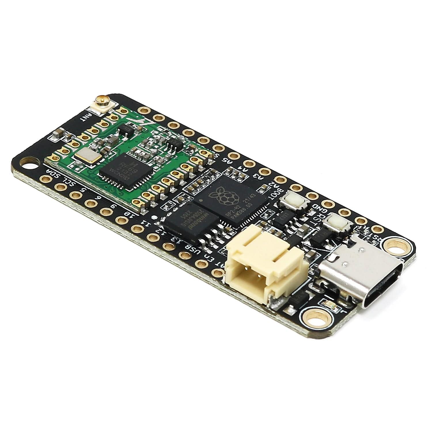
The iLabs Challenger RP2040 Sub-GHz 915MHz board is an Arduino/Micropython compatible Adafruit Feather format microcontroller board based on the RP2040 chip used in the Raspberry Pico.
This is a spin-off from our Challenger RP2040 LoRa board, but in this case, we've replaced the LoRa module with a low-power Sub-GHz radio module also from Hope RF. The transceiver features a proprietary long-range modem that provides ultra-long-range spread spectrum communication and high interference immunity whilst minimizing current consumption.
This is the Sub-GHz 915MHz version. We also offer a Sub-GHz 868MHz option...or view the entire Challenger range here!
The RFM69HCW is a transceiver module capable of operation over a wide frequency range, including the 315, 433, 868 and 915MHz license-free ISM (Industry Scientific and Medical) frequency bands. Currently, we are only supporting the 868 and 915MHz bands but this may change in the future.
All major RF communication parameters are programmable and most of them can be dynamically set. The RFM69HCW offers the unique advantage of programmable narrow-band and wide-band communication modes.
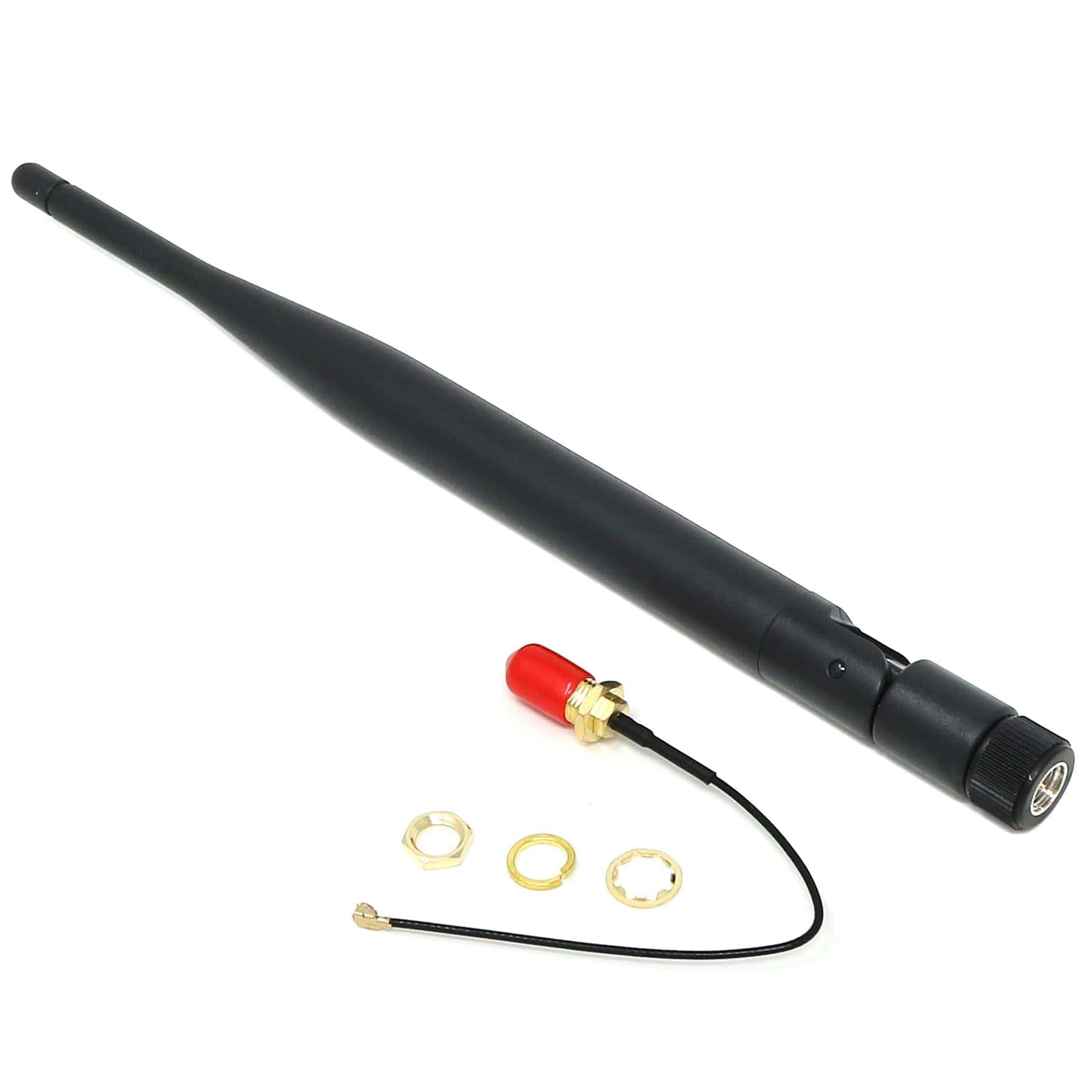
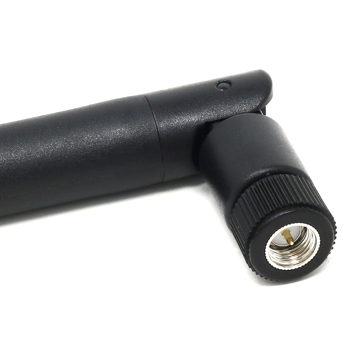
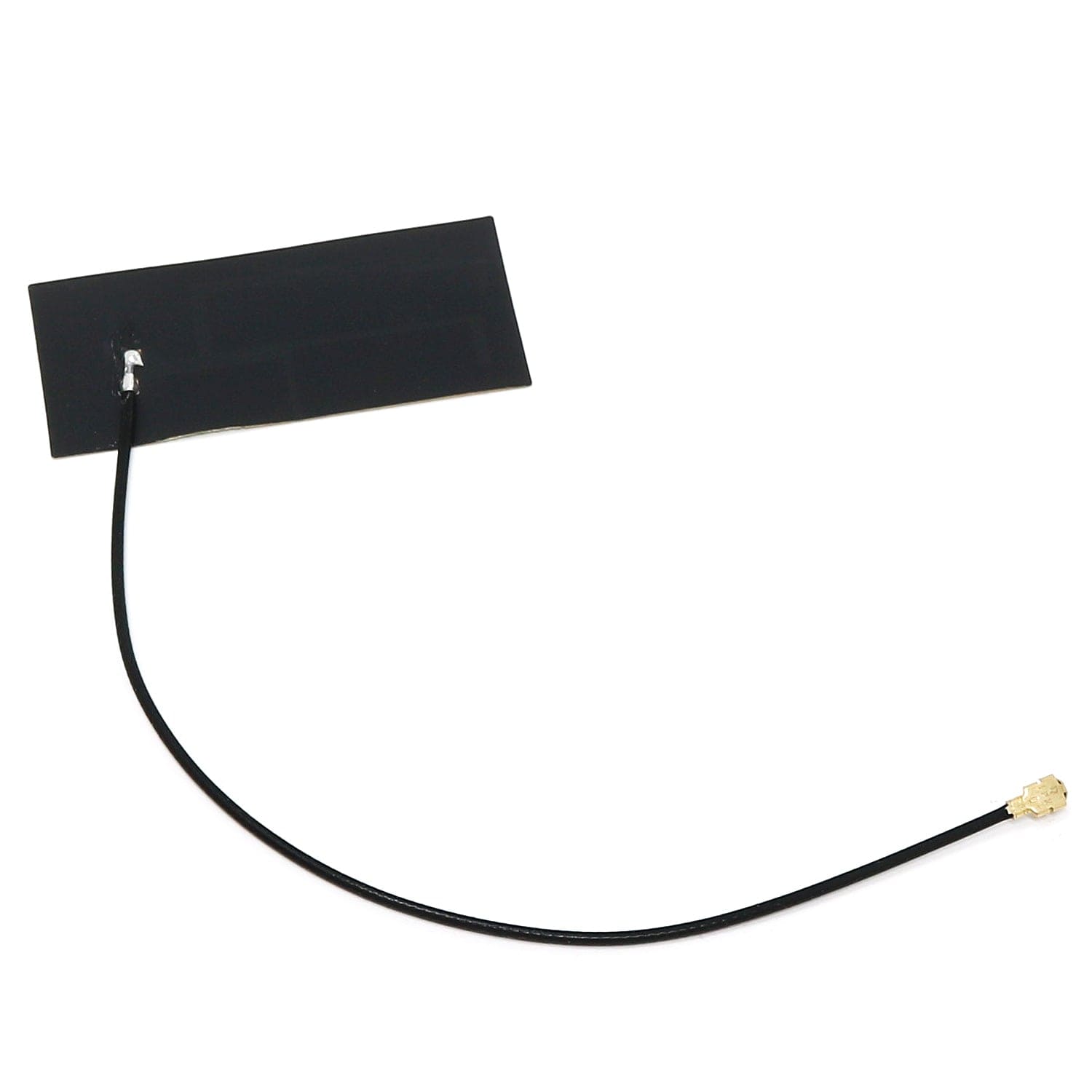
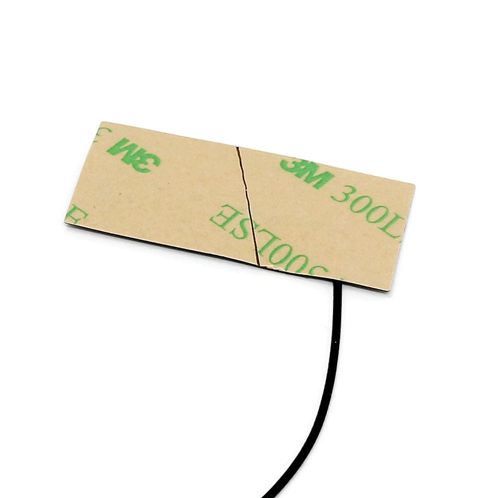
The RFM69HCW is connected to the RP2040 via SPI channel 1 and a few GPIOs that are required for signalling. A U.FL connector is used to attach your antenna to the board.
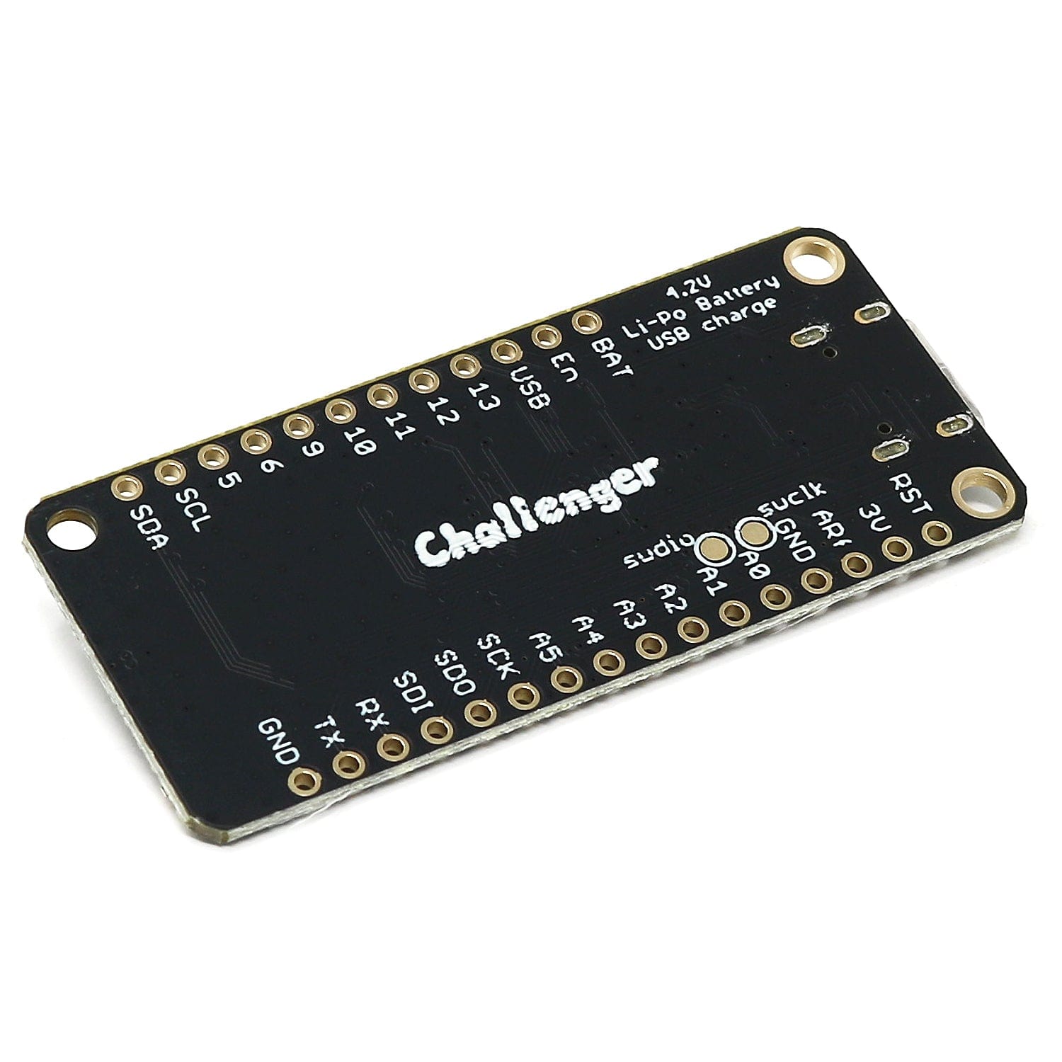
The board can be powered by multiple sources. The most obvious way to run the board is by plugging it into a USB cable and attaching it to your computer. In this mode, you can write software and test the board with all its functionality.
You can also supply the board with 5V via the header connectors on the PWR pin.
There is a third way to supply the board too. This way is more invasive and will disable the onboard 3.3V power regulator. When doing this you will have to pull the EN header pin low and then supply your own 3.3V voltage on the 3.3V header pin. Please note that when disabling the onboard power regulator you will have to supply the 3.3V also when running the system on battery power.
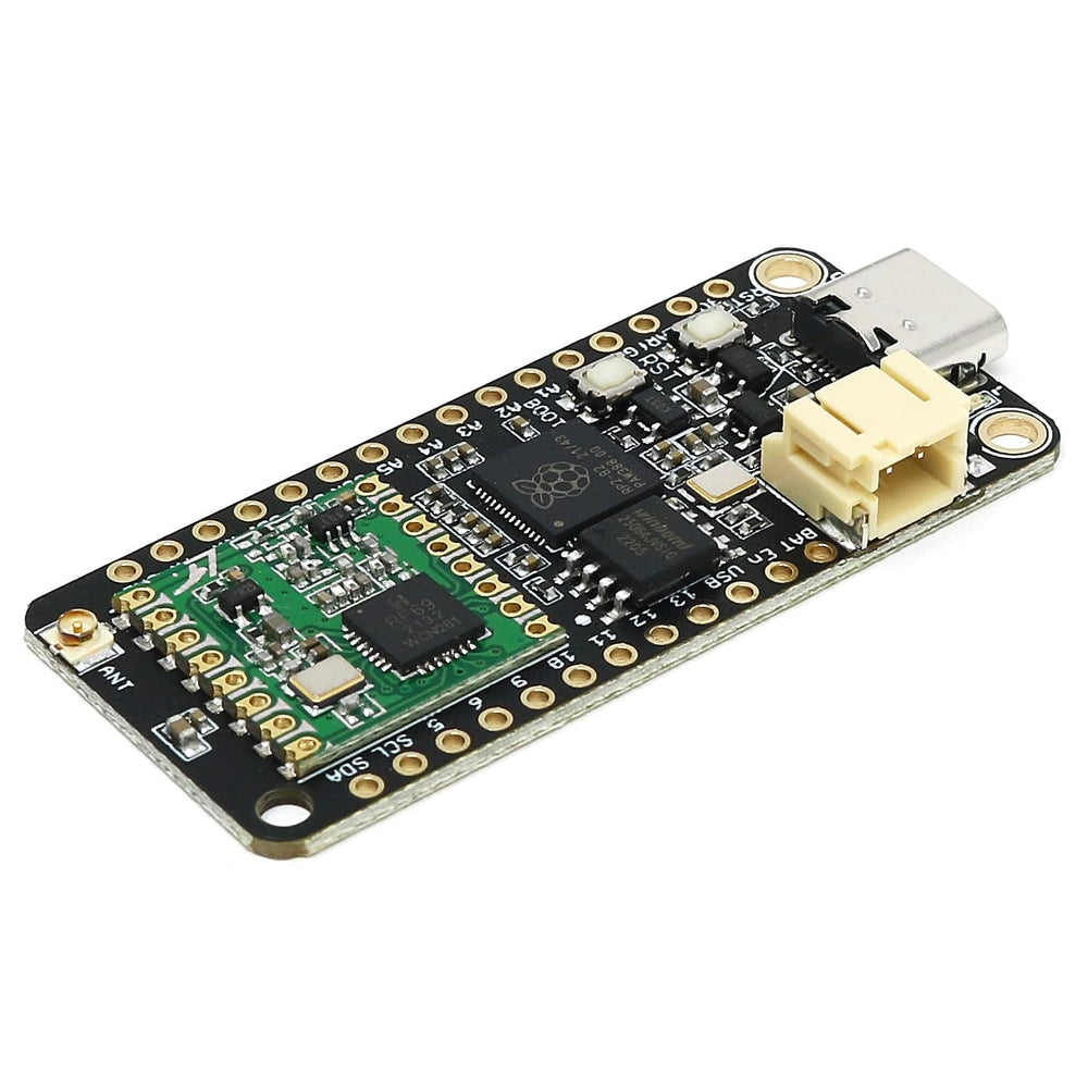
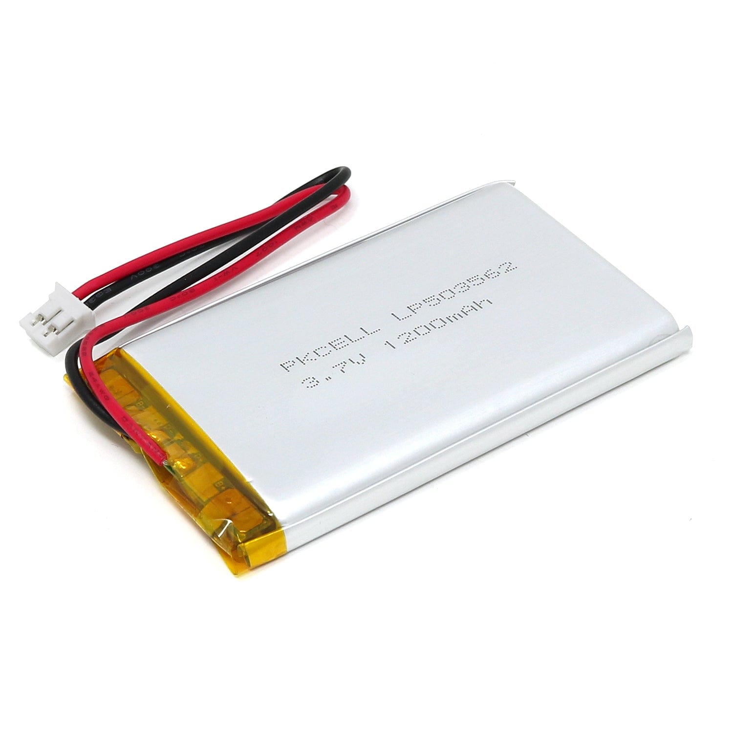
As described earlier the board can be powered by a LiPo battery. The battery can be connected using a standard 2.0mm JST connector through the battery connector on the right side of the board or if the battery is an integral part of the system that you are designing it is possible to connect the battery through the BAT pin instead.
Switching between the battery voltage and the applied USB voltage or external 5V is done seamlessly by the onboard circuitry.
Charging of the battery is achieved by either connecting a USB cable or by connecting a 5V power source to the header pin marked USB on the board. If you do this make sure you connect your voltage through a 1A schottky diode to avoid any excessive current draw in the system when the two levels are slightly different.
Please note that providing external charger circuitry could destroy the internal charger on the Challenger board.
On each side of the USB connector, there is a small indicator LED. The LED which is marked CHG is the charge control indicator. This red LED will light whenever the connected battery is being charged, and when the battery is fully charged the LED will turn off again. If you haven’t connected a battery to the board this LED will not come on at all.
On the other side of the USB connector, there is a user-programmable green LED. This LED is connected to pin D15 and can easily be controlled by the user program.
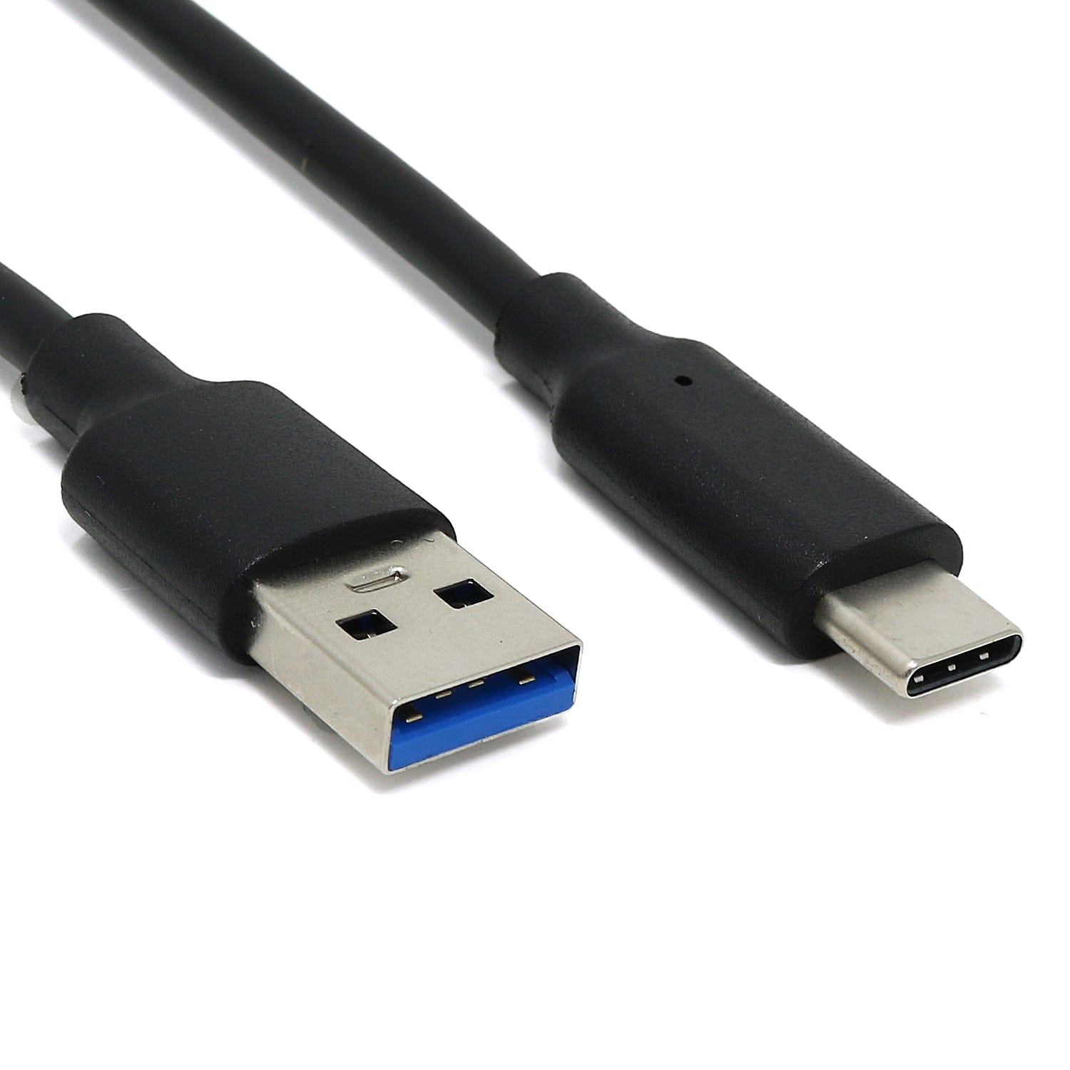
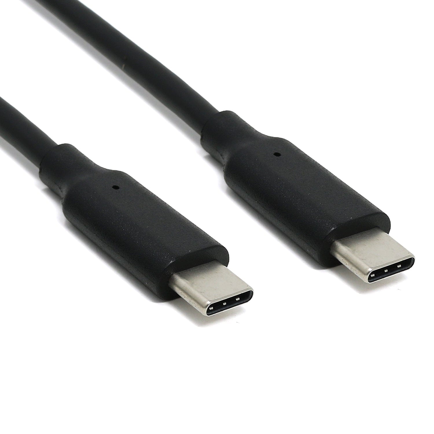
In recent years we have noticed that we are seeing more and more USB Type-C cables laying around the lab due to the fact that most new phones and accessories use them. So iLabs decided to go for a USB Type-C connector for this board. A bonus of this is that they are more durable and you don’t have to fiddle with the cable before plugging it in!
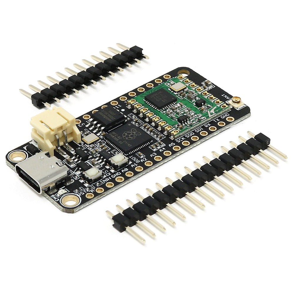
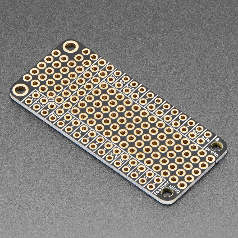
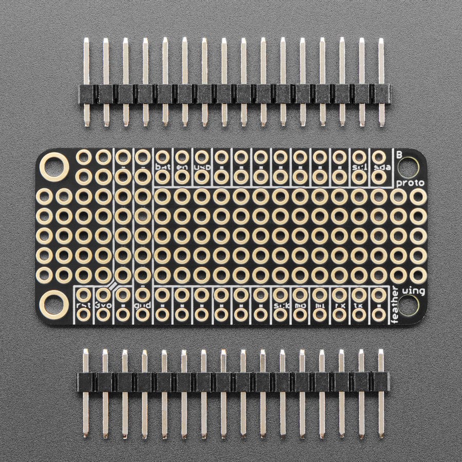
The board comes with loose headers that can be soldered to the board if your application requires it.

| Board Size | 50,80 mm x 22,86 mm x 3,20 mm |
| Main microcontroller | RP2040 from Raspberry Pi |
| SPI | Two SPI channels configured |
| I2C | One I2C channel configured |
| UART | One UART channel configured |
| Analog inputs | 4 analog input channels |
| Radio module | RFM69HCW from Hope RF |
| FLASH Memory | 8MByte 133 MHz |
| SRAM Memory | 264KByte |
| USB 2.0 controller | Up to 12MBit/s full speed |
| JST Battery connector | 2.0mm pitch |
| On board LiPo charger | 450mA standard charge current |
The Challenger is fully compatible with both the micropython package found at the Raspberry Pi site as well as Adafruit's CircuitPython. Instruction on how to install the python interpreter of your choice is available on the respective websites.
iLabs teamed up with Earle F. Philhower over at his Github page to provide Arduino support for their RP2040/Pico based boards. All instructions on how to install the board support package as well as multiple examples on how to use the Raspberry Pi Pico processor.
Your payment information is processed securely. We do not store credit card details nor have access to your credit card information.