Building Automation 8-Layer Stackable HAT for Raspberry Pi (v5.0)
Price:
Sale price
£92.50
Stock:
 Skip to content
Login / Signup
Cart
Your cart is empty


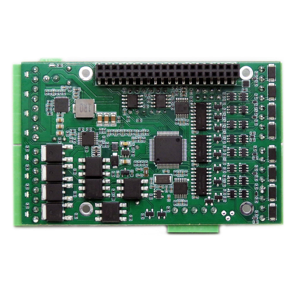


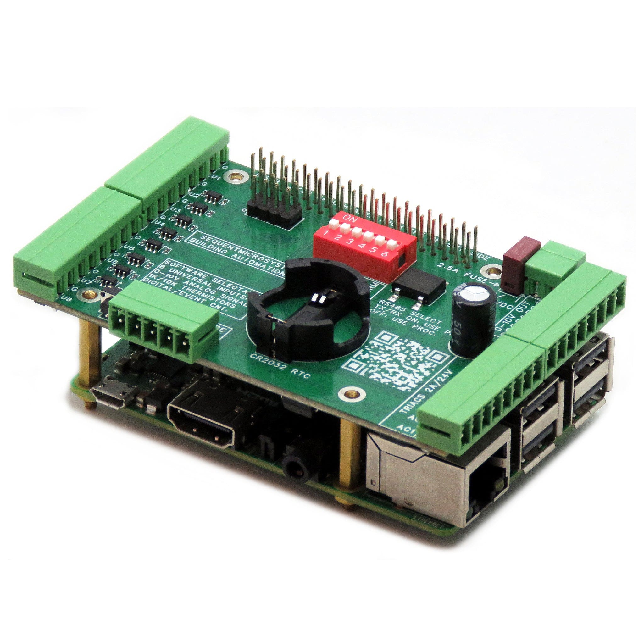
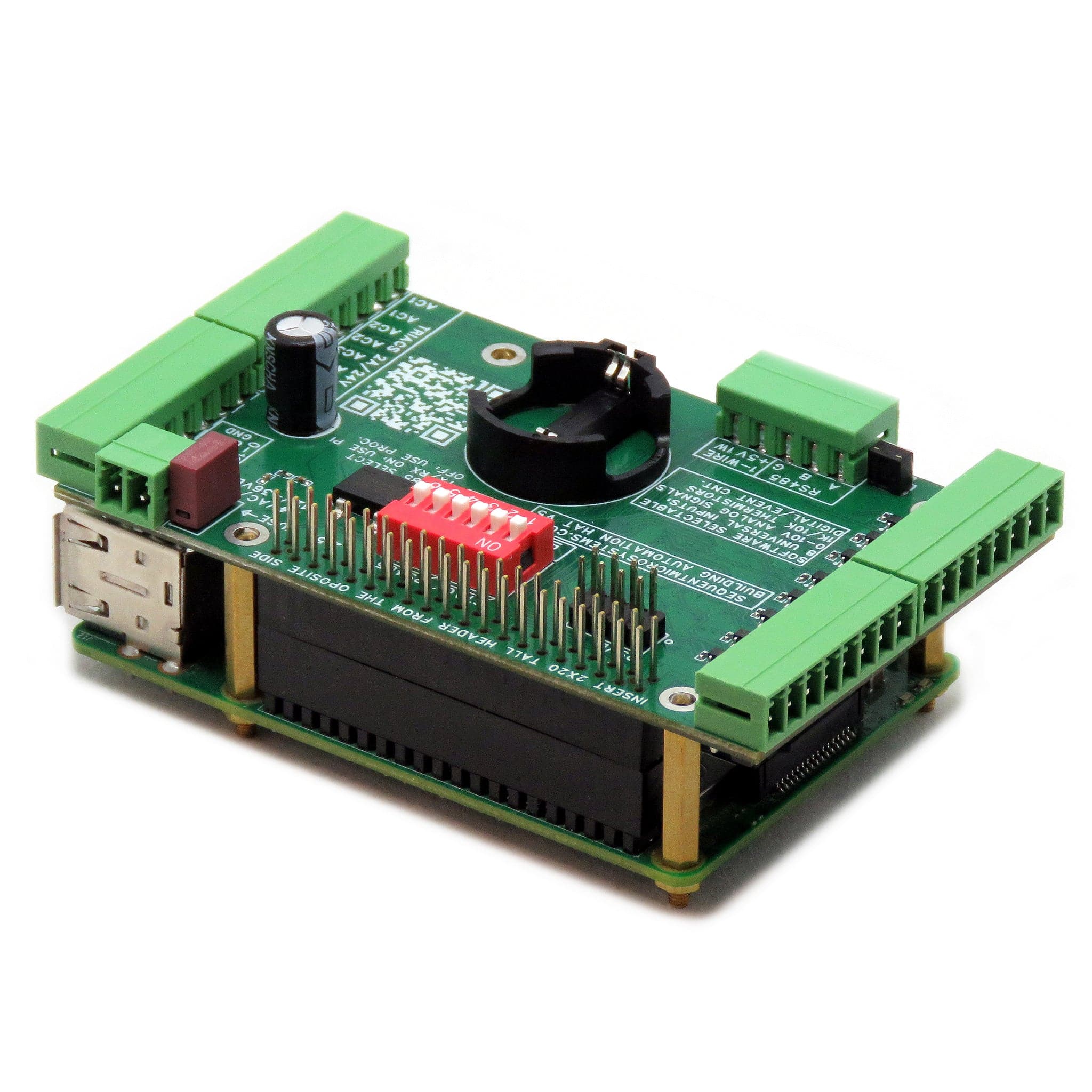
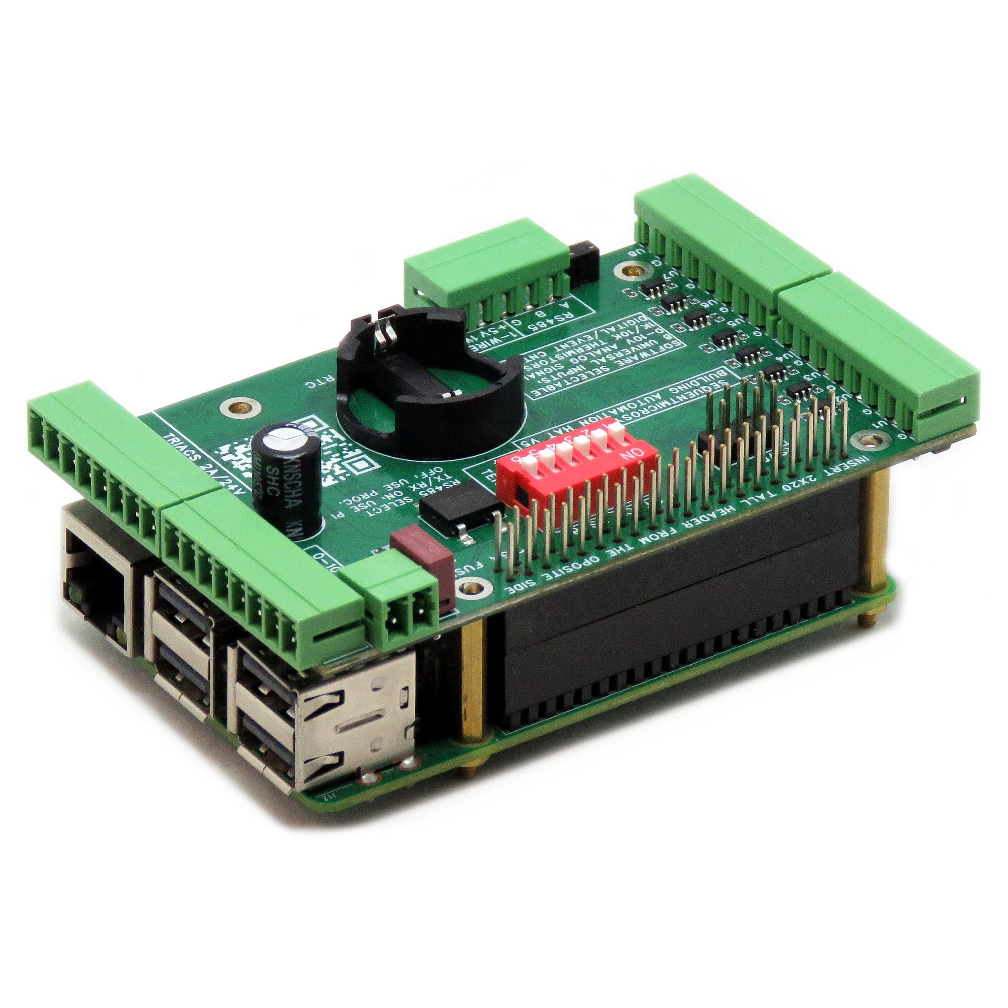
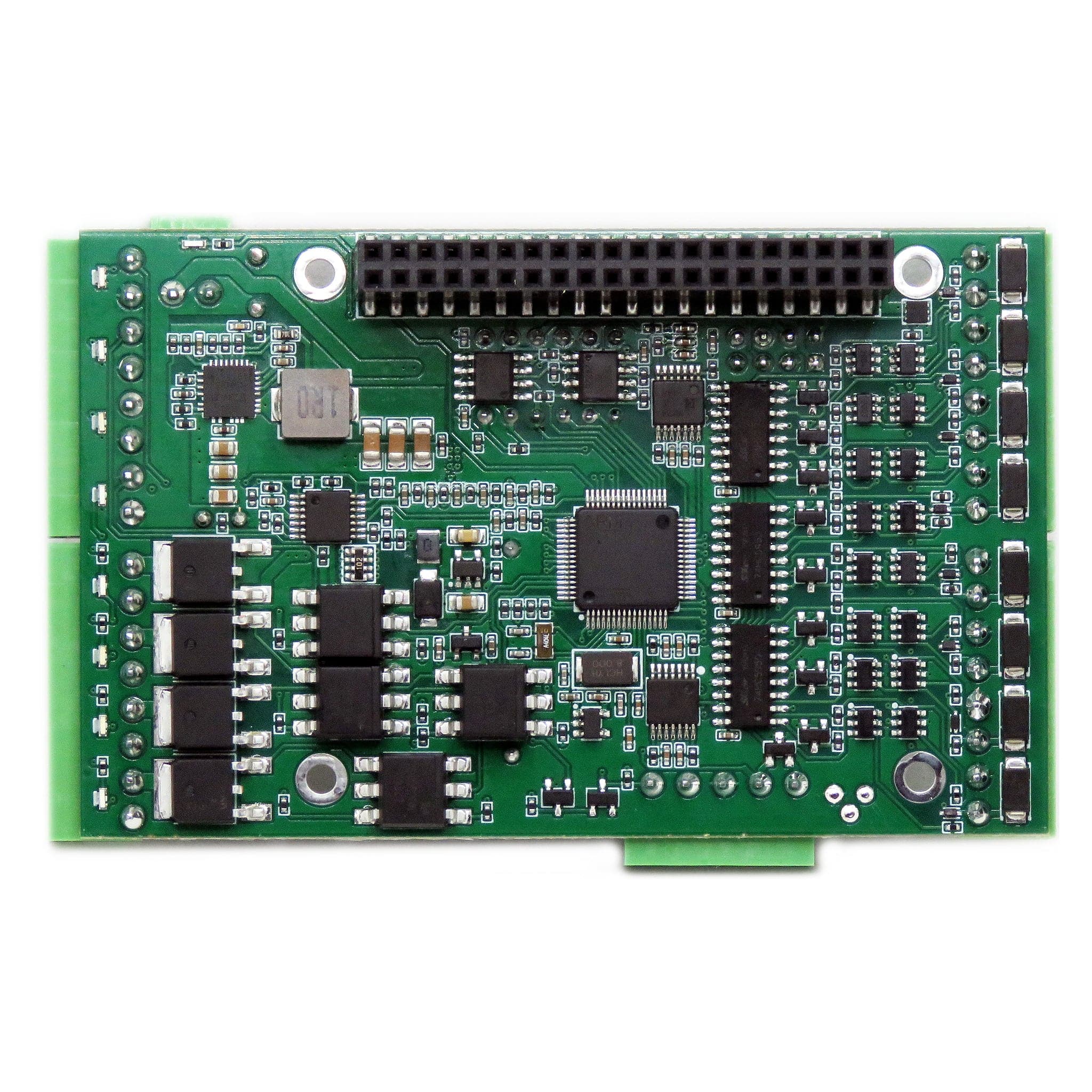
This HAT gives your Raspberry Pi all IO needed for Building Automation Systems.
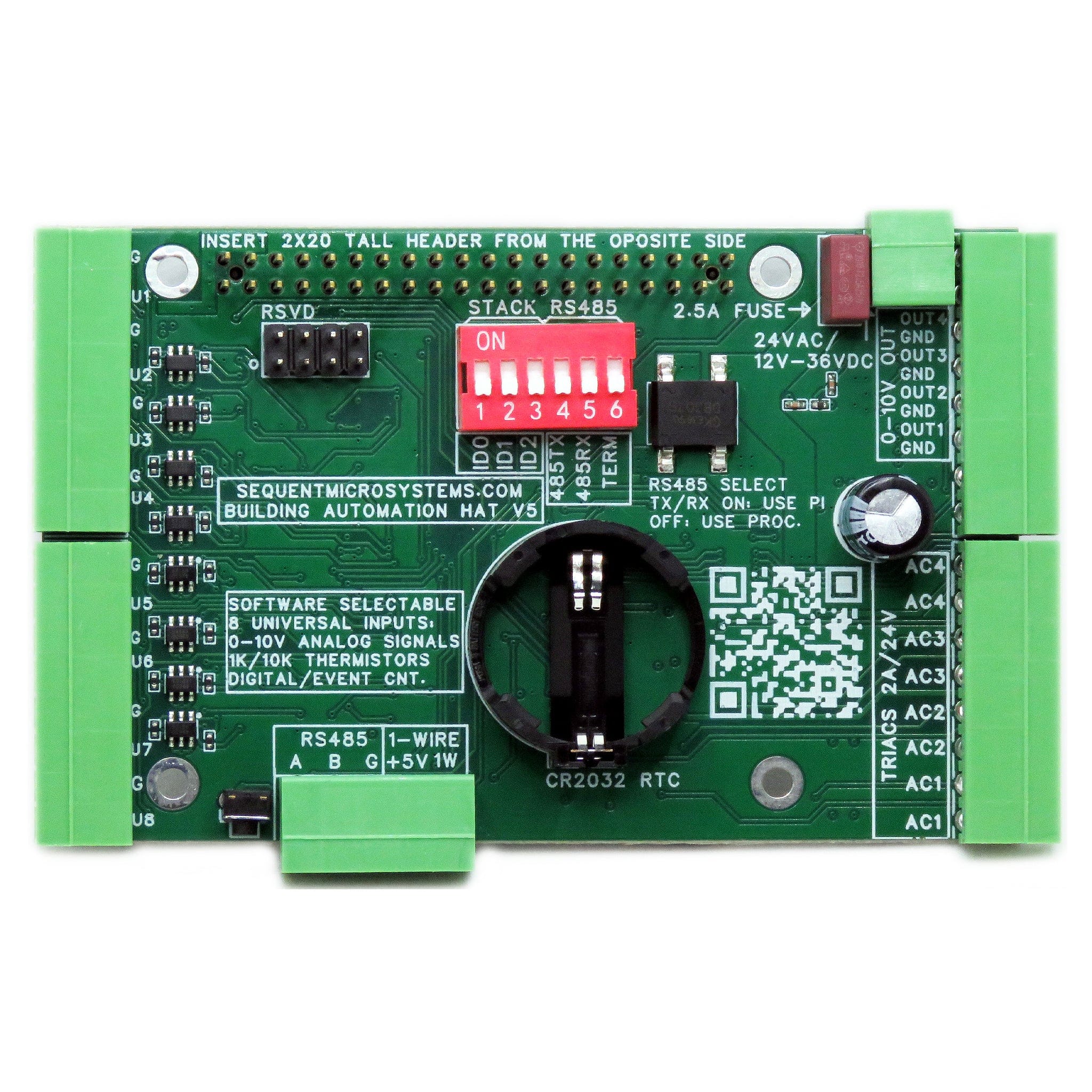
Eight universal inputs can be software selected to process 0-10V signals, read 1K or 10K temperature sensors or dry contact counters.
Four TRIAC outputs can drive loads up to 1A at 24VAC, and four 0-10V outputs can control light dimmers. Status LEDs display the state of all outputs.
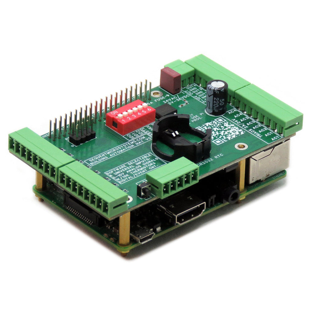
Keep time indefinitely, even during a power failure, using the Real Time Clock with battery backup (CR2032).
Connect up to 16 DS18B20 temperature measurement devices on the 1-Wire interface.
Activate the hardware watchdog to monitor and power cycle the Raspberry Pi in case of software lockup.
TVS diodes on all inputs protect the card from external ESD, and the onboard resettable fuse protects it from accidental shorts.
Heavy loads of up to 8A and 250VAC can be driven by adding one or more 4-RELAYS cards. High DC loads of up to 10A and 250V, with fast response time and unlimited endurance can he driven by adding one or more 8-MOSFET cards.
The latest version of the HAT has also a standard 1-Wire interface. Up to 16 DS18B20 temperature measurement devices can be connected in parallel. Devices can be accessed from the command line of from the MODBUS interface.
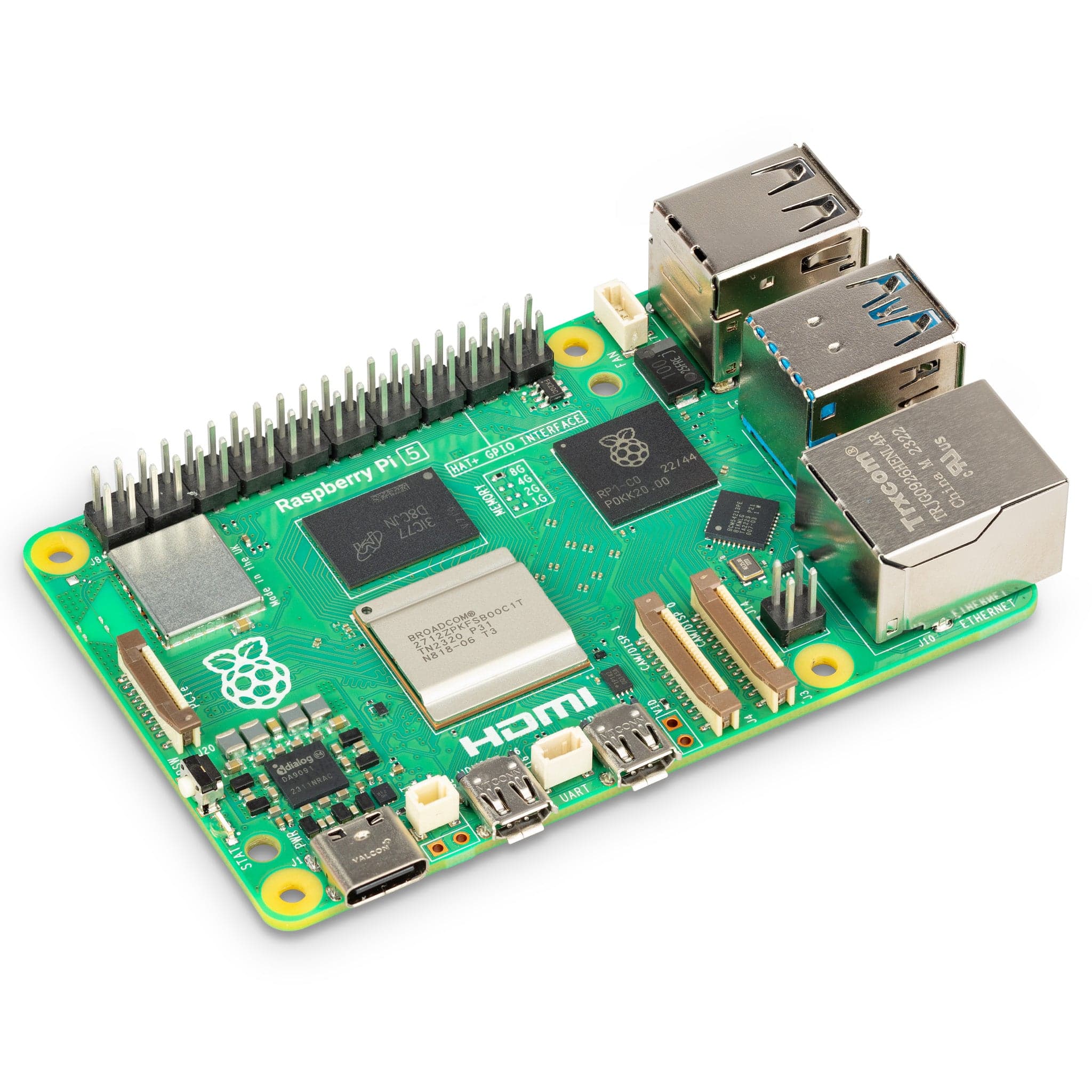
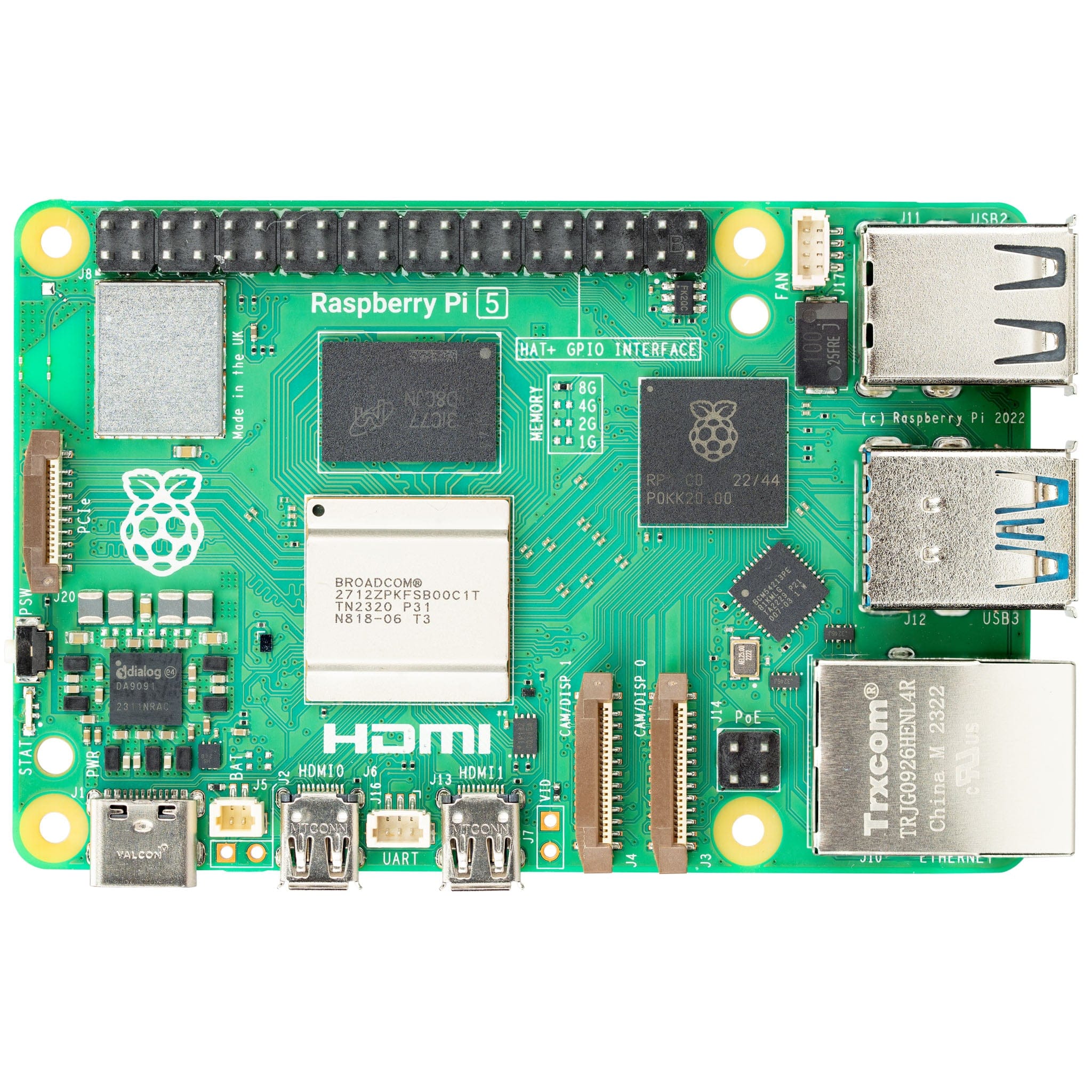
The card shares the I2C bus using only two of the Raspberry Pi’s GPIO pins to manage all eight cards. This feature leaves the remaining 24 GPIOs available for the user. The card is compatible with all Raspberry Pi versions from Zero to 5 and has all the necessary I/Os for your Building Automation projects.
The card requires a 24VAC/1A external transformer to operate and has to be powered from its own pluggable connector. The card supplies 5V and up to 3A to the Raspberry Pi on the GPIO bus. A local 3.3V regulator powers the rest of the circuitry. The card needs 50mA to operate.
All the IO's are connected to heavy-duty (8A), 3.5mm pitch pluggable connectors which make field wiring very convenient for installation and debugging.
A six-position DIP switch is used to select the source of the RS485 port and the position of the card in the stack, if multiple cards are used.
Up to eight cards can be stacked on your Raspberry Pi. Three positions of the configuration DIP Switch labeled ID0, ID1, ID2 are used to select the stack level. Cards can be stacked in any order.
The card has an RS485 port which can be driven from the Raspberry Pi, or from the local processor. Leave the TX and RX switches in the OFF position to connect the port to the local processor. Set both to ON to connect to USART1 on the Raspberry Pi GPIO connector.
When DIP Switches are ON, Raspberry Pi can communicate with any device with an RS485 interface. In this configuration, the card is a passive bridge which implements only the hardware levels required by the RS485 protocol. To use this configuration, you need to tell the local processor to release control of the RS485 bus:
~$ megabas [0] rs485wr 0 0 0 0 0
When DIP Switches are OFF, the card operates as MODBUS slave and implements the MODBUS RTU protocol. Any MODBUS master can access all the card's inputs and set all the outputs using standard MODBUS commands. A detailed list of commands implemented and parameter addresses can be found on GitHub:
In both configurations the local processor needs to be programmed to release (jumpers installed) or control (jumpers removed) the RS485 signals. See the command line online help for further information.
The last position on the DIP switch is the RS485 line terminator. Set it to ON if the card is last on the RS485 chain.
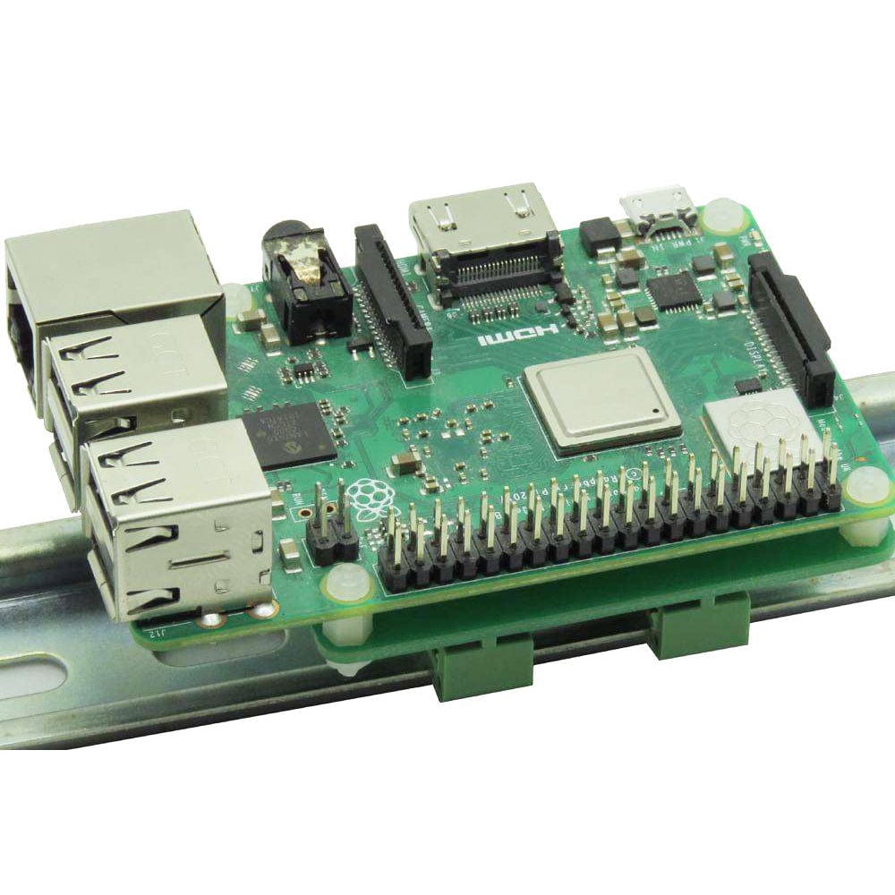
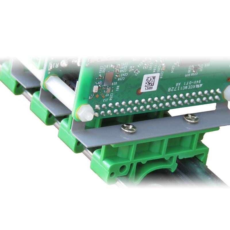
DIN-Rail Mounting
The card can be installed parallel on a DIN-Rail using the DIN-Rail Kit Type 1, or perpendicular using the DIN-Rail Kit Type 2.
~$ git clone https://github.com/SequentMicrosystems/megabas-rpi.git
~$ cd /home/pi/megabas-rpi
~/megabas-rpi$ sudo make install
~/megabas-rpi$ megabas
The program will respond with a list of available commands.
The default setting of the Universal Inputs is 0-10V. To change it:
For more info on the commands type "megabas -h incfgwr" and "megabas -h incfgrd"
You can write your own application using the Command Line or Python Libraries provided. No programming is required if you use the Node-Red nodes provided. You can drag-and-drop the functional blocks to design your application. Examples are provided at GitHub. CODESYS drivers also provided.
All the analog inputs and outputs are calibrated at the factory, but firmware commands permit the user to re-calibrate the board, or to calibrate it to better precision. All inputs and outputs are calibrated in two points; select the two points as close to possible to the two ends of scale. To calibrate the inputs, the user must provide analog signals. (Example: to calibrate 0-10V inputs, the user must provide a 10V adjustable power supply). To calibrate the outputs, the user must issue a command to set the output to a desired value, measure the result and issue the calibration command to store the value. Calibration process can be done using command line interface provided, type "megabas -h" for a complete list of command options
The card contains a built-in hardware watchdog which will guarantee that your mission-critical project will recover and continue running even if Raspberry Pi software hangs up. After power up the watchdog is disabled, and becomes active after it receives the first reset or first period set.
The default timeout is 120 seconds. Once activated, if it does not receive a subsequent reset from Raspberry Pi within 2 minutes, the watchdog cuts the power and restores it after 10 seconds.
Raspberry Pi needs to issue a reset command on the I2C port before the timer on the watchdog expires. The timer period after power up and the active timer period can be set from the command line. The number of resets is stored in flash and can be accessed or cleared from the command line. All the watchdog commands are described by the online help function.
The card firmware can be updated in the field by running a command. The update is made with the latest firmware version located on our servers. More instructions about the process can be found on GitHub. Please make sure there is no process, like Node-Red or python scripts, that tries to access the card during the update process.
Your payment information is processed securely. We do not store credit card details nor have access to your credit card information.