Servo 2040 - 18 Channel Servo Controller
Price:
Sale price
£24
Stock:
Quantity:
 Skip to content
Login / Signup
Cart
Your cart is empty

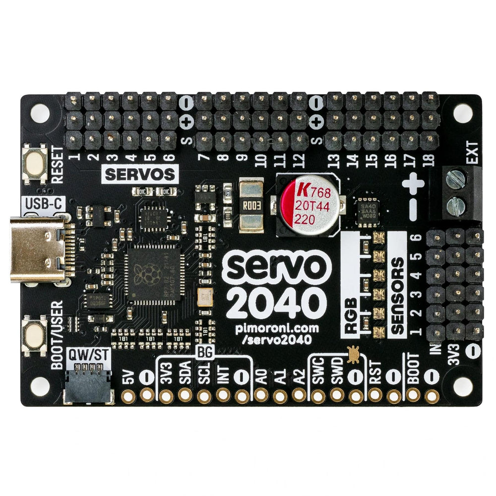

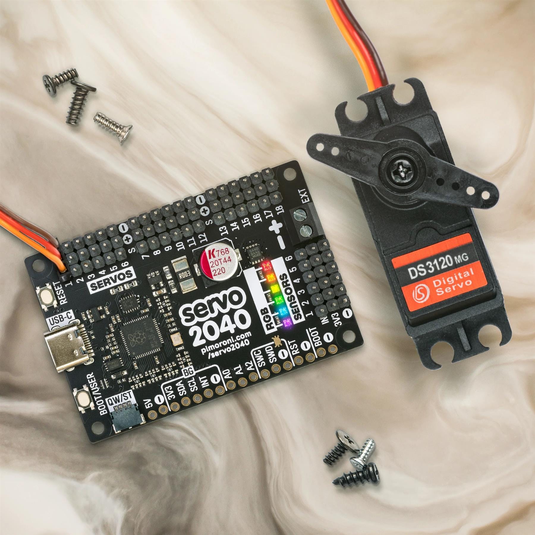
Build the hexapod/robot arm/other articulated contraption of your dreams with this all-in-one RP2040 powered servo controller with current measurement, sensor headers and RGB LEDs.
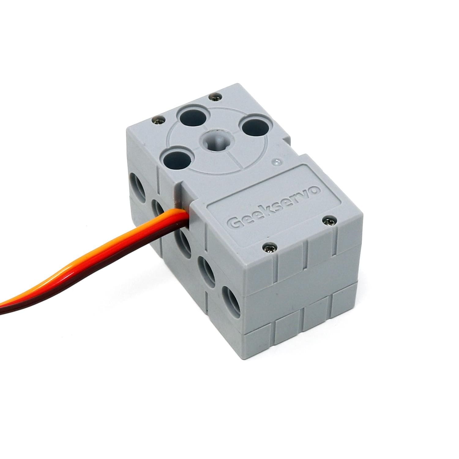
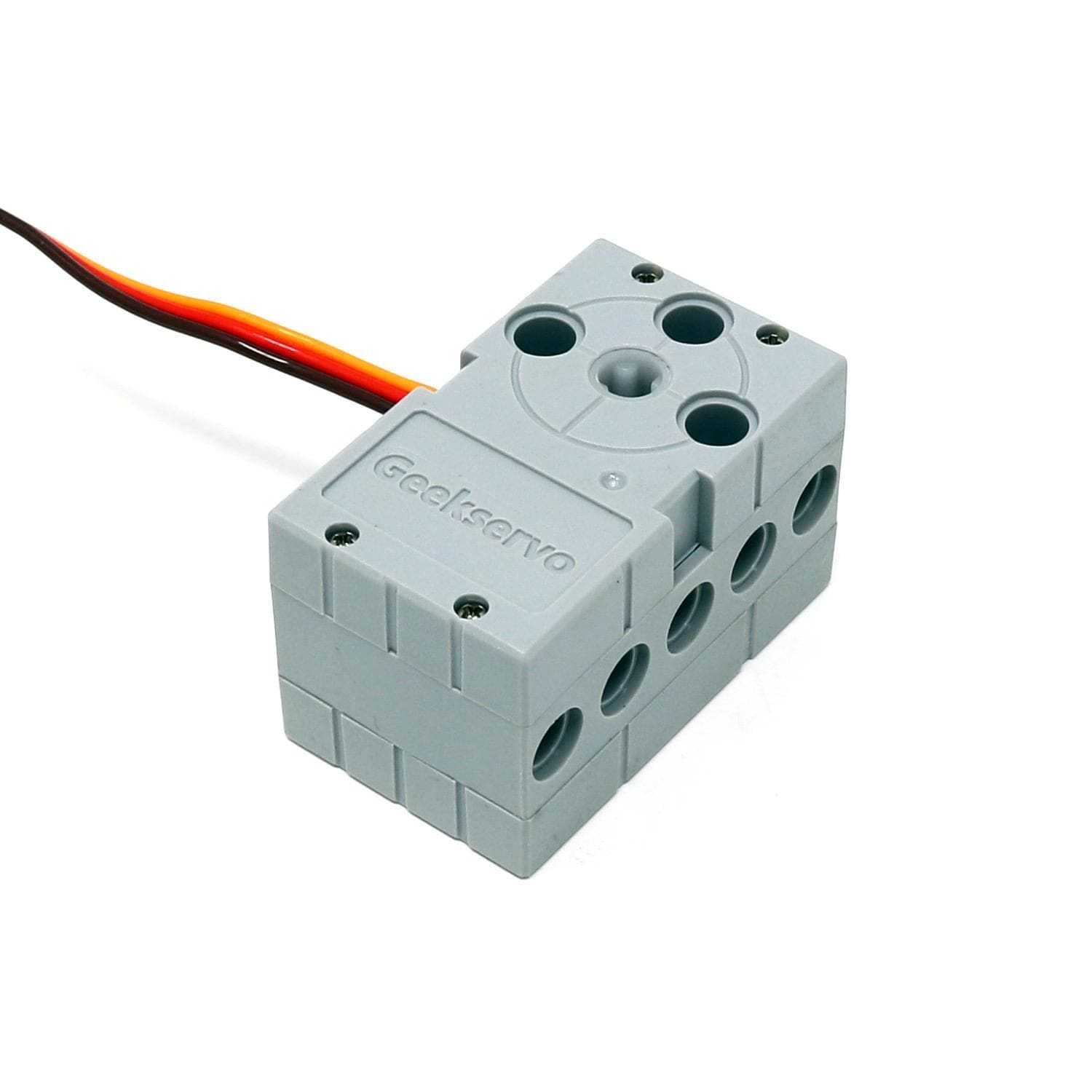
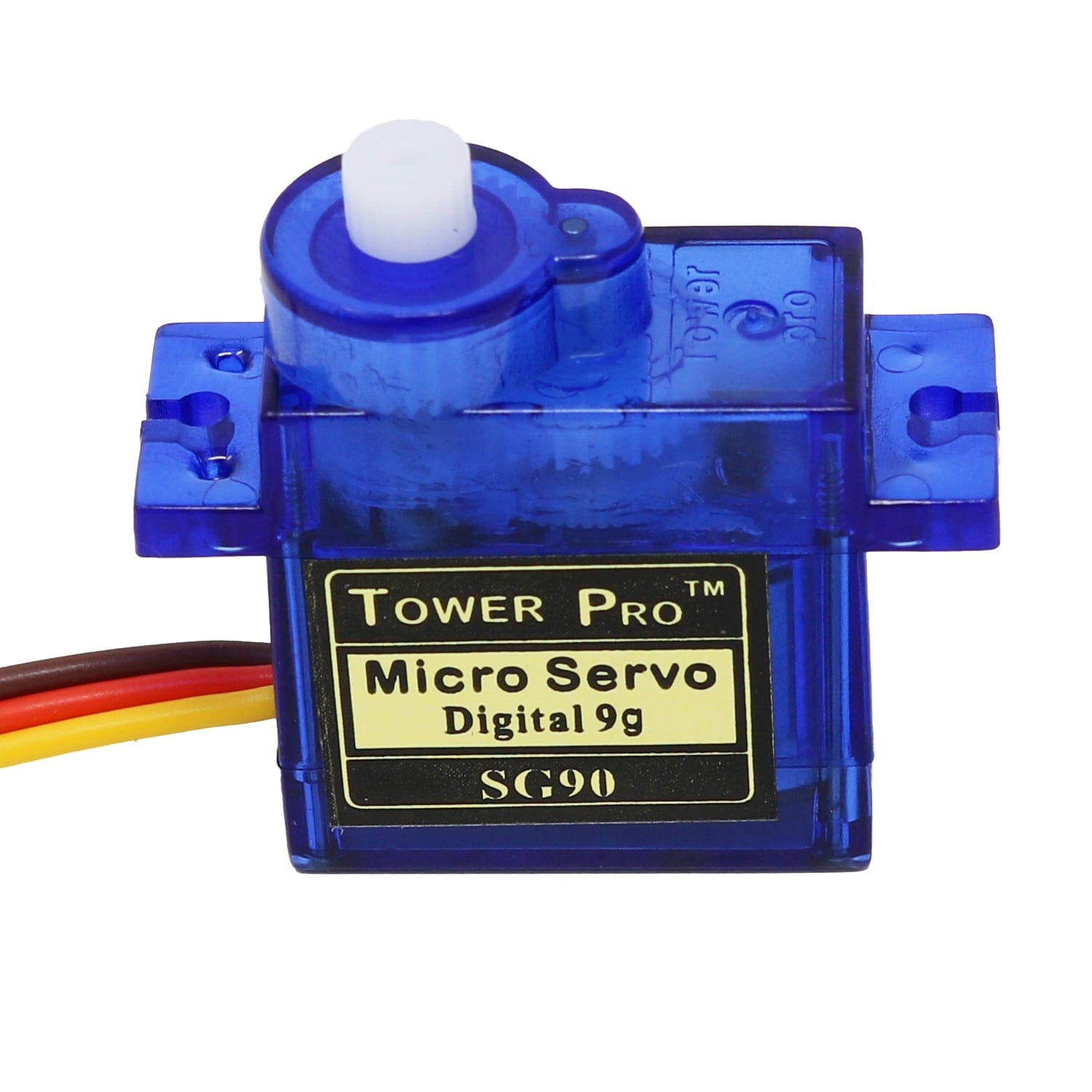
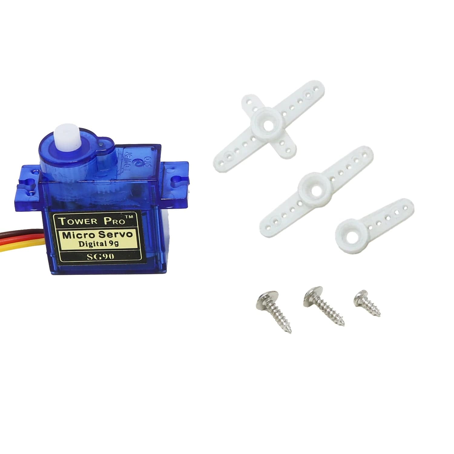
Servo 2040 is a standalone servo controller for making things with lots of moving parts. It has pre-soldered pin headers for plugging in up to 18 servos - enough for the leggiest of hexapod walkers or plenty of degrees of freedom for your robotic arms, legs or tentacles (servos not included). Servos can be pretty power-hungry, especially the chunky ones, so we've added some neat current monitoring functions so you can keep an eye on power consumption.
There are six addressable RGB LEDs (AKA Neopixels) for visual feedback and status reports, plus pin headers to connect up to six analog sensors - useful for sensing where the ground is, if you're about to crash into a wall, or how much pressure The Claw is exerting on your hapless test subject. We've also popped a QW/ST connector on there, to make it super easy to add a Qwiic or STEMMA QT breakout or two.
Servo 2040 is supported by a well documented C++/MicroPython servo library with lots of examples to show you how to use the individual features (and everything together).

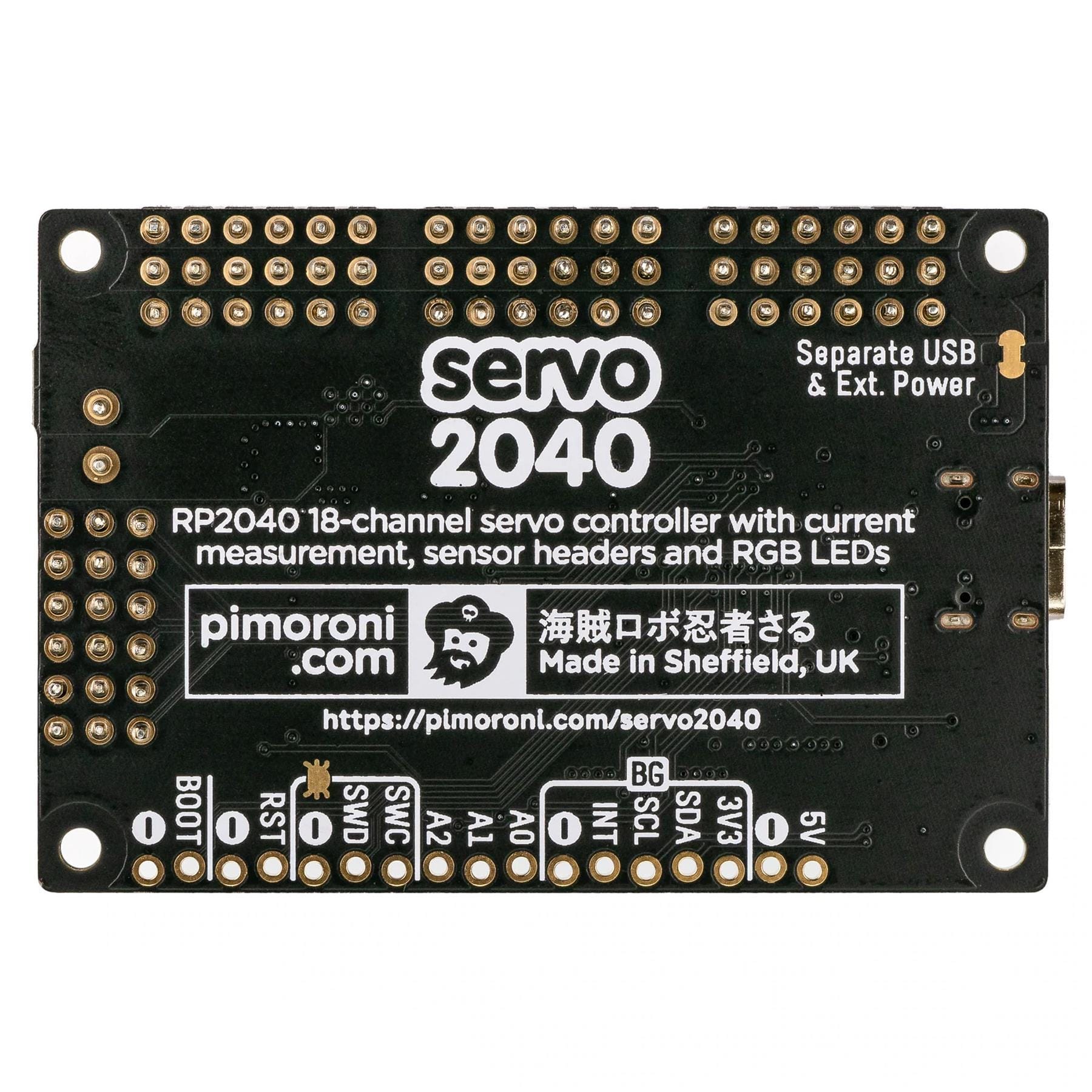
We've used the RP2040 as the core of this board because of the flexibility of its Programmable IOs (PIOs). Traditionally, each servo needs to be connected to its own PWM capable channel on the microcontroller. RP2040 only has 16 PWM channels, but it's possible to drive up to 30 servos using the magic of PIOs (if you're canny with wiring). RP2040's PIOs are also super fast, so they can drive servos with sub microsecond resolution.
We've built the RP2040 microcontroller right into Servo 2040, so you don't need a separate microcontroller and servo driver boards. This makes for nice compact builds - perfect for small robots!
Because it's an RP2040 board, Servo 2040 is firmware agnostic! You can program it with C/C++, MicroPython or CircuitPython.
Our C++/MicroPython libraries will help you get the most out of Servo 2040, they're packed with powerful features for working with servos. You'll get the best performance using C++, but if you're a beginner we'd recommend using our batteries included MicroPython build for ease of getting started.
You can also use CircuitPython on your Servo 2040, if you want access to all the nice conveniences of Adafruit's ecosystem (note that you will only be able to control up to 16 servos with CircuitPython).
If your breakout has a QW/ST connector JST-SH to JST-SH cable, or you can easily connect any of our I2C Breakout Garden breakouts with a JST-SH to JST-SH cable; coupled with a Qw/ST to Breakout Garden adaptor.
Your payment information is processed securely. We do not store credit card details nor have access to your credit card information.