Using a Tactile Switch with the Raspberry Pi
Buttons and switches are a fundamental part of ‘physical’ computing. This beginner’s tutorial is designed to teach the basics of physical operation with the Raspberry Pi using a simple momentary switch setup. It requires a few simple components, available from ModMyPi (scroll to the bottom to see the products):
- Medium Breadboard
- Male to Female Jumper Wires
- PCB Mount Switch
- ModMyPi’s Ridiculous Resistor Kit:
- 10K? Resistor: Brown, Black, Black, Red, Brown
- 1K? Resistor: Brown, Black, Black, Brown, Brown
- Breadboard Jumper Wire Kit
Step 1 - Building the circuit
The circuit enables the Raspberry Pi detect a change in voltage when the button (Switch 1) is pressed and requires three GPIO pins. The first will provide a signal voltage of 3.3V (Vcc), the next will ground the circuit (GND), and the third will be configured as an input (GPIO IN) to detect the voltage change.
When a GPIO pin is set to input, it doesn’t provide any power and consequently has no distinct voltage level; defined as ‘floating’. We need the pin to be capable of judging the difference between a high and low voltage, however in a floating state it can incorrectly detect states due to electrical noise. To enable the pin to perceive the difference between a high or low signal we must ‘tie’ that pin, calibrating it to a defined value; 3.3V in this case!
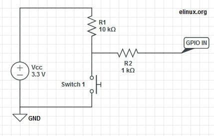
To tie the input pin, we connect it to the Vcc 3.3V pin, hence when Switch 1 is open, the current flows through GPIO IN and reads high. When Switch 1 is closed, we short the circuit and the current is pulled to GND; the input has 0V, and reads low! As we are connecting Vcc directly to GND, which could allow are dangerous current to flow, the large R1 (10kΩ) resistor ensures that only a little current is drawn. To make the circuit even safer, we add the R2 (1kΩ) resistor to limit the current to and from GPIO IN.
The Switch
Four point switches are wired in a very similar manner to two point switches. They’re simply more versatile, as you can have multiple isolated inputs into the same switching point. Checking the diagrams, Pins 1 & 2 are always connected, as are Pins 3 & 4. However, Pins 1 & 2 are isolated from Pins 3 & 4. When the button is pressed the two sides are linked and Pins 1, 2, 3 & 4 are all connected!
In ‘momentary’ switches the circuit disconnects when pressure is removed from the button, as opposed to ‘toggle’ switches when one push connects and the next push disconnects the internal switch circuit.


Where does it all go?
WARNING. When hooking up to GPIO points on your Raspberry Pi care must be taken, as connecting the wrong points could permanently fry your Pi. Please use a GPIO cheat-sheet, and double check everything before switching it on. Each GPIO point will be denoted by name and physical location. For example, GPIO P17 is actually located at Pin 11, denoted: GPIO P17 [Pin 11]. The irregularities are a result of the pin names being referenced by the on board chip rather than their physical location.
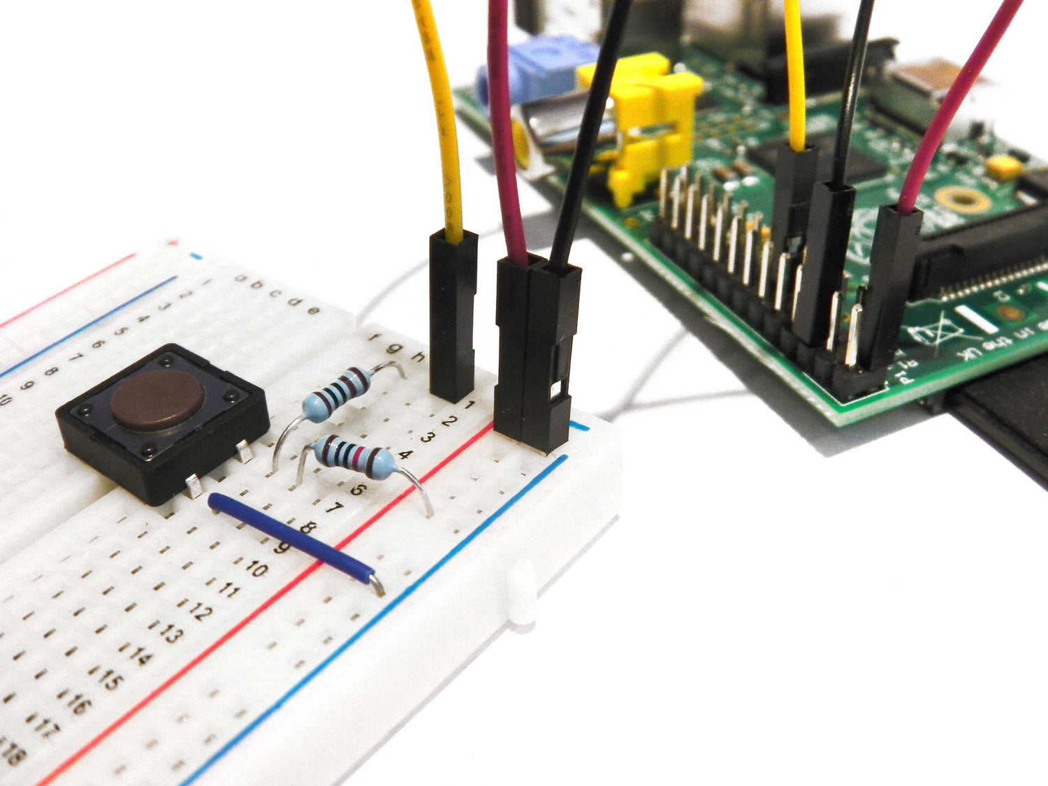
1. Connect Pi to Ground Rail. Use a black jumper wire to connect GPIO GND [Pin 6] on the Pi to the Negative (-) rail on the breadboard.
2. Connect Pi 3.3V to Positive Rail. Use a red jumper wire to connect GPIO 3.3V [Pin 1] on the Pi to the Positive (+) rail on the breadboard.

3. Plug your switch in. When breadboarding, make sure all of the legs are in separate rows. To achieve this straddle the central channel on the breadboard.
4. Add 10kΩ Resistor. Connect from Switch Pin 1, to the Positive (+) rail. Orientation of standard film resistors is unimportant.

5. Connect Switch to Ground. Use a breadboard jumper wire to hook Switch Pin 3 to the Negative (-) rail.

6. Connect Switch to 1kΩ Resistor. Add this resistor between Switch Pin 1 and the 10kΩ Resistor, and take it to a clear rail.

7. Connect Switch to Signal Port. We’ll be using GPIO P17 to detect the 3.3V signal when the switch is pressed. Simply hook up a jumper between GPIO P17 [Pin 11] on the Pi and the 1kΩ Resistor rail.
That’s our circuit built! Next we’ll write a simple program in Python to run when we press the switch!
Step 2 - Making a program in Python
In this part, we’ll go through the steps of programming and interacting between the Pi and our components. The coding part of this tutorial will be completed on Python, a widely used general purpose language. It’s also very readable, so we can break down and explain the function of each line of code. The purpose of our code will be to read the I/O pin when the switch is pressed!

Install the GPIO Python Library
Before we can get started we need to install the RPi.GPIO Python library. Please follow the link here for a guide on how to so then come back here once your done!
Making a Program in Python
With the GPIO library installed, we’re all ready to start our Python project! Load up the Raspian GUI with startx, and load the program IDLE 3 into which we’ll type our code. As we’re starting a new project, open up a new window File>>New Window. Remember that Python is case sensitive, and indentation is fundamental. Indentation, which is used to group statements, will occur automatically as you type commands, so make sure you stick to the suggested layout.
The first line of our code imports the Python library we’ve just downloaded into our project.
import RPi.GPIO as GPIO
We next need to set our GPIO pin numbering, as either the BOARD numbering or the BCM numbering. BOARD numbering refers to the physical pin numbering of the headers. BCM numbering refers to the channel numbers on the Broadcom chip. Either will do, but I personally prefer BCM numbering. If you’re confused, use a GPIO cheat sheet to clarify which pin is which!
GPIO.setmode(GPIO.BCM)
Now you need to define the GPIO pins as either Inputs or Outputs. In Part 1, we set BCM Pin 17:BOARD Pin 11 (GPIO P17 [Pin 11]) as our input pin. So our next line of code tells the GPIO library to set this pin as an input.
GPIO.setup(17, GPIO.IN)
In part 1 of the tutorial the input pin was tied high by connecting it to our 3.3V pin, and the purpose of our Python programme is to check to see if the if the input pin has been bought low e.g. when the button has been pressed. To check the high/low status of the pin we’re going to use a True or False statement running on an infinite loop.
We need to tie our true statement to the high value of our input pin. To do so we create a new variable called input_value and set it the current value of GPIO P17 [Pin 11].
while True:
input_value = GPIO.input(17)
Next we'll add some code so that the program will display a message when the button is pressed. For this, we’ll use the False statement e.g. when the input_value (which is tied high) is no longer equal to the input_value, which occurs when the button is pressed and it’s pulled low, execute a command.
If input_value == False
print(''Who pressed my button!")
When the button is pressed the program will now display the text: “Who pressed my button!”, feel free the change this to anything you want.
while input_value == False:
input_value = GPIO.input(17)
The last two lines in the above code are very important, they create a loop that tells Python to keep checking the status of GPIO P17 [Pin 11] until it's no longer low (button released). Without this, the program would loop while the button is still being pressed meaning the message will be printed multiple times on the screen before you release the button.
The final program should look like this in python:

Save the file as button.py. In order to run the program, open a new terminal window on the Pi and type the following command:
sudo python button.py
At first nothing will happen, but if you press the button the program will print the defined message.

To exit a running Python script, simply hit CTRL+C on the keyboard to terminate.
If it hasn't worked don't worry. First check the circuit is connected correctly on the breadboard as defined in part 1, then that the jumper wires are connected to the correct pins on the GPIO port. If it still fails to work, double check each line on the program is correcting remembering that python is case-sensitive and indentation is correct. I find that typing the code out by hand will give better results than a simple copy/paste.
This is a deceptively simple program that can be used for many purposes. The same code could be used to read when the pins of separate devices, such as a sensor or external micro-controller, have been pulled high or low. Next time we’ll add an LED to our circuit, and make it flash on command from our button!




2 comments
The Pi Hut
@Keith – It’s a common addition yes, but it needs a bit of trial & error to get the delay just right for the application/user. You can also look into ‘interrupts’ which may be another useful method.
@Keith – It’s a common addition yes, but it needs a bit of trial & error to get the delay just right for the application/user. You can also look into ‘interrupts’ which may be another useful method.
Keith
It is worth putting in a time.sleep(x) line where x is a suitable interval to prevent bouncing
It is worth putting in a time.sleep(x) line where x is a suitable interval to prevent bouncing