Raspberry Pi GPIO Sensing: Motion Detection
In previous tutorials, we outlined the basics behind physical computing and the Raspberry Pi by activating LEDs and scripts using a simple one button circuit. If you haven’t read the previous tutorials please do so, as they include a few points (such as basic Python programming and Board/BCM GPIO numbering) that will be skipped in this tutorial.
In this tutorial, we’ll expand on previous lessons by transplanting a button with a PIR sensor (to sense motion). This tutorial will outline how to assemble the circuit with a PIR sensor, and devise a simple script to print a message when the sensor detects movement. In the next tutorial we’ll add a buzzer and LEDs to our sensing circuit to raise an alarm when an intruder is detected!
PIR Sensors
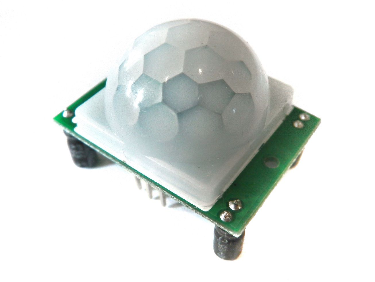
PIR sensors, often referred to as, "Passive Infrared" or "IR motion" sensors, enable you to sense motion. Everything emits a small amount of infrared radiation, and the hotter something is, the more radiation is emitted. PIR sensors are able to detect a change in IR levels of their detection zone (e.g. when a human enters a room) and hence sense motion.
The PIR sensors we’ll be using in this tutorial have three pins: ground, digital out and 3-5VDC in. At idle, when no motion has been detected, the digital out will remain low, however when motion is detected, the digital out will pulse high (3.3V) and we’ll use our Raspberry Pi to sense this! The PIR sensors we’ll be using in this tutorial have a range of approximately 7 meters, and a 110° x 70° detection range, so it’s great for monitoring a door or the corner of a room.
For this exercise you will require:
- Breadboard
- 6 x Male to Female Jumper Wires
- PIR Sensor
Assemble the Circuit
Note. We could hook the PIR directly to the Pi’s GPIO pins (and it would work well!) however, as we’re going to add extra features later, we’ll construct it on a breadboard.
1. Plug three of your male to female jumper wires into the three pins on the PIR sensor. The three pins are labelled as the following: Red; PIR-VCC (3-5VDC in), Brown; PIR-OUT (digital out) and Black; PIR-GND (ground).

2. Plug PIR-VCC into the positive rail of your breadboard, plug PIR-GND into your negative rail, and plug PIR-OUT into any other blank rail.
3. Use a black jumper wire to connect GPIO GND [Pin 6] on the Pi to the negative rail of your breadboard. This is the same rail that we’ve added out PIR-GND wire.
4. Use a red jumper wire to connect GPIO 5V [Pin 2] on the Pi to the positive rail of your breadboard. This is the same rail that we’ve added our PIR-VCC and will power our PIR sensor.
5. We’ll be using GPIO 7 [Pin 26] as an input to sense when our PIR detects motion. Therefore the final step is to connect GPIO 7 [Pin 26] to the same rail as our PIR-OUT.

Sensing with Python
Now that we’ve hooked our PIR up to our Pi, we need to program a Python script to register when the PIR senses movement!
In our switch tutorial, we had to tie our input high and then have our Python programme define the difference between whether the input was high or low. The PIR on the other hand will always output low (0V) unless movement is detected, in which case it will output high (3.3V). We can therefore simply set our PIR-OUT GPIO pin as an input, and use Python to detect any voltage change.
First, import the Python GPIO library, import our time library (so we make our Pi wait between steps) and set our GPIO pin numbering.
import RPi.GPIO as GPIO
import time
GPIO.setmode(GPIO.BCM)
Next, we need to give our input pin a name, so that we can refer to it later in our Python code. Naming it “PIR_PIN” will enable us to read if the PIR is outputting a signal (e.g. movement has been detected). You can name a pin variable almost anything, so try playing around to see what you can get away with.
PIR_PIN = 7
We then need to define our GPIO pin that we just named PIR_PIN as an input.
GPIO.setup(PIR_PIN, GPIO.IN)
The next step is to add some cool text so that we know our PIR, Pi and Python programme are ready to detect movement. You can leave this out, or change it to anything you want! The following will print two lines of text with a two second gap between them.
print “PIR Module Test (CTRL+C to exit)”
time.sleep(2)
print “Ready”
To check the input status of PIR_PI we’re going to use a True statement running on an infinite loop.
while True:
if GPIO.input(PIR_PIN):
print “Motion Detected!”
time.sleep(1)
The code will then continuously check the PIR_PIN input, and will print a line of text if the input goes high. The time limit between each loop means that you should only have one output when movement is detected, as the PIR_PIN will switch low once the movement has stabilised.
That’s it! We can wrap our programme in a short piece of clean-up code to ensure that it exits cleanly. This isn’t compulsory, but it’s good practice.
import RPi.GPIO as GPIO
import time
GPIO.setmode(GPIO.BCM)
PIR_PIN = 7
GPIO.setup(PIR_PIN, GPIO.IN)
try:
print “PIR Module Test (CTRL+C to exit)”
time.sleep(2)
print “Ready”
while True:
if GPIO.input(PIR_PIN):
print “Motion Detected!”
time.sleep(1)
except KeyboardInterrupt:
print “ Quit”
GPIO.cleanup()

That’s it, a very simple method of connecting and coding a low cost movement sensor with the Raspberry Pi.
If you message just keep looping and looping you might have your PIR’s sensitivity set too high. Our PIRs have potentiometers on board which can adjust this. Clockwise increases sensitivity, so work backwards until you get the sensitivity you require!
Interrupt Driven Sensing
The code above utilises GPIO “polling” to detect the state of the pin. Polling consists of an infinite loop, which continually checks the status of the pin until we see the high signal. Polling utilises a lot of CPU power unfortunately, and you will most likely see some system slowdown whilst performing other tasks.
Adding the “time.sleep” line in our code means that our Pi checks the pin less frequently which should reduce performance problems. The issue with using a time break in your code is that you could miss a pin event (during the sleep cycle), so it’s not ideal, and we’re still looping the function rapidly! There is another way. . .
GPIO interrupts allow a program to wait for GPIO events. Instead of repeatedly checking a pin, the code waits for a pin to be triggered, essentially using zero CPU power. Interrupts are known as “edge detection”; an edge defining the transition from high to low “falling edge” or low to high “rising edge”. A change in state, or transition between low and high, is known as an “event”.
Interrupts are single event functions, so we need some way to loop it. Obviously looping our interrupt code would defeat the point of using it, e.g. we’d be “polling” the interrupt function instead of the GPIO pin. We’re therefore going to loop some low resource code instead, and link our interrupt to a “call-back” function. Call-backs are functions that are only started when an event takes place.
If you envisage waiting for a letter: polling is the act of you waiting at home all day, holding open the letter box and peering out waiting for the postman to arrive. An interrupt in this scenario would be a camera that watches the street for the postman. When it spies the postman it calls your mobile phone (the call-back) to let you know the postman is 10 minutes from your doorstep. This would free you up, allowing you to get on with other things and even leave the house!
PLEASE NOTE. RPi.GPIO version 0.5.1 (or greater) is required for this code to work. “sudo apt-get update” and “sudo apt-get dist-upgrade” will upgrade everything!
The first step is to define (def) our call-back function. We’re going to name our call-back “MOTION” and link it to our PIR_PIN. As before, we want this function to print some text when we detect motion.
def MOTION(PIR_PIN):
print “Motion Detected!”
Adding the following line enables interrupts on the pin, and tells the code to wait until an event occurs e.g. when our PIR_PIN detects a signal. The pin can be configured to wake when shifting low to high (GPIO.RISING), high to low (GPIO.FALLING) or either one (GPIO.BOTH). We then tell it which call-back to use!
GPIO.add_event_detect(PIR_PIN, GPIO.RISING, callback=MOTION)
As mentioned previously we need to add a simple and non-intensive looping function to ensure our event detection stays live. We can therefore loop a sleep function! We could use the “while True” function here; however due to the ability to redefine “True” to a different value it increase the code load slightly (whilst it looks up the variable). Using an integer “while 1” skips that variable check.
while 1:
time.sleep(100)
That’s it! We’ve coded a low resource program with integrated interrupt and call-back function that senses the output from a Motion Detector!
Final Code
import RPi.GPIO as GPIO
import time
GPIO.setmode(GPIO.BCM)
PIR_PIN = 7
GPIO.setup(PIR_PIN, GPIO.IN)
def MOTION(PIR_PIN):
print “Motion Detected!”
print “PIR Module Test (CTRL+C to exit)”
time.sleep(2)
print “Ready”
try:
GPIO.add_event_detect(PIR_PIN, GPIO.RISING, callback=MOTION)
while 1:
time.sleep(100)
except KeyboardInterrupt:
print “ Quit”
GPIO.cleanup()


