

MicroPython Skill Builders - #7 SPI OLED Displays
Welcome to the seventh instalment of our MicroPython Skill Builders series by Tony Goodhew, aiming to improve your coding skills with MicroPython whilst introducing new components and coding techniques - using a Raspberry Pi Pico!
In this episode, Tony will teach you how to use OLED displays with the Raspberry Pi Pico using SPI communication. We covered I2C communication with OLEDs in a previous article, however Tony is tackling SPI today!
Need to catch up? Check out our tutorials section for the previous episodes.
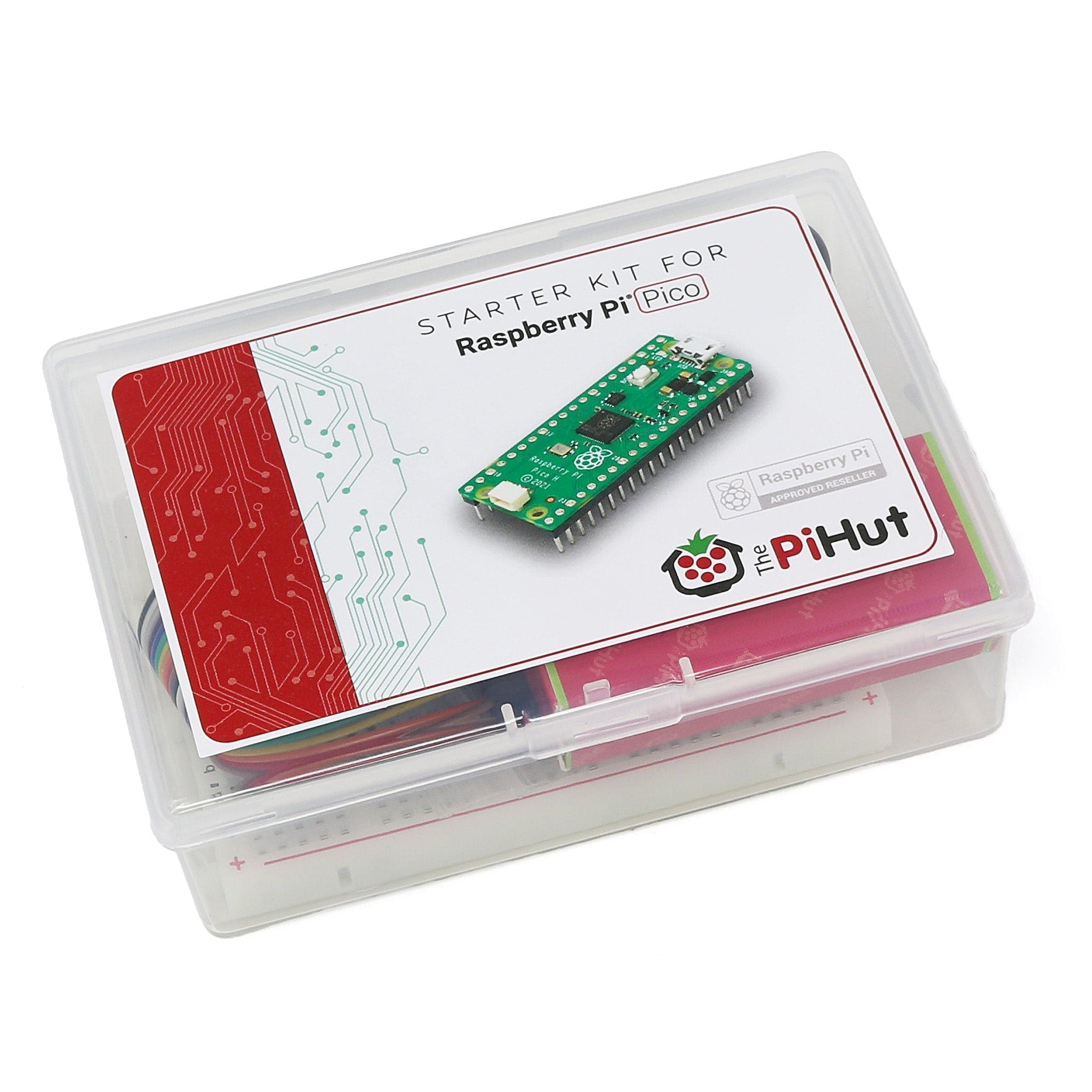
What you will need
We assume that you have installed Thonny on your computer and set up your Raspberry Pi Pico with the most recent MicroPython firmware (UF2). If not, check out our Raspberry Pi Pico Getting Started Guide where this is covered in detail.
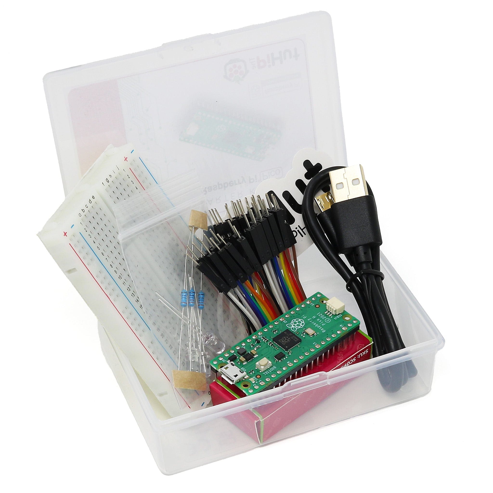
You will need:
- Raspberry Pi Pico with header pins
- A full-size breadboard
- Micro-USB cable (for power and programming the Pico)
- Jumper wires (male/male and male/female, mixed colours ideally)
- Waveshare 0.96” OLED Module (or the blue or white version)

OLED Display options
Colour
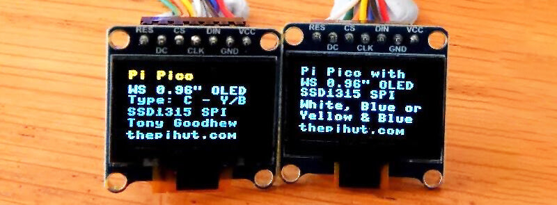
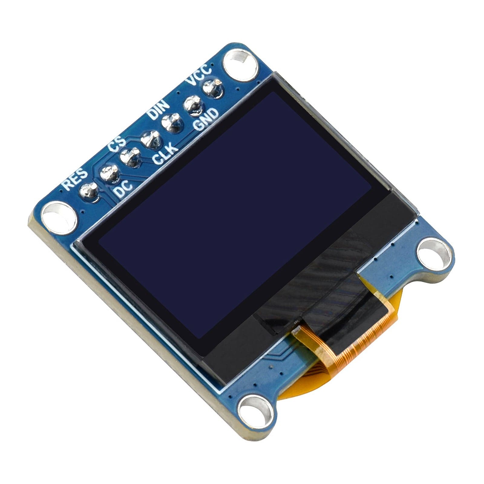
Today we're using the yellow/blue version of Waveshare's 0.96" OLED in our examples - all-white and all-blue are also available. OLED stands for Organic Light-Emitting Diode.
The yellow/blue display has yellow pixels in the top 25% of the screen and blue in the lower 75% of the screen
All versions have 128 pixels across the screen and 64 pixels downward. They are small but very bright and clear. They can be used to display both text and graphics and make an ideal introduction to programming displays.
I2C or SPI
They can be connected by either SPI (default setting, no soldering required) or I2C (needs some soldering skills and library adjustment – see our previous tutorial).
We will use the provided cables to connect via SPI (Serial Peripheral Interface). You can find the Waveshare's own documentation here, however it does not cover connection to a Raspberry Pi Pico - but we have found a way!
SPI Homework!
Unsure on SPI? You can find an excellent introduction here!.
Our article today uses modern language and does not include the same references to the original terms and connection labels, such as MISO and MOSI, from the eighties (this is interesting but very long and complicated - we suggest you come back to it later as you can use the display without fully understanding all of its detail).
In our example, MAIN is the Pico and SUBNODE is the display.
SPI OLED code library
It's very easy to get the display working. What we need is code to drive the display and we can download a library to provide it. Although this display uses a SSD1315 chip it is compatible with the SSD1306 chip, so we can use the SSD1306 library.
Install the code library
We need to install the micropython-ssd1306 library to allow us to use this display. Follow the steps below.
Note - we're installing the library manually as, at the time of writing, the plug-in menu method isn't working.
- Go to this link
- Select all of the code on that page (use Ctrl+A) and copy it over to Thonny
- In Thonny, select File > Save as and choose Raspberry Pi Pico as the destination
- Call the file ssd1306.py
- Select OK
- IMPORTANT - You must now close this ssd1306.py file (use the little X on that tab) then open a new one for your code (File > New)
If this was successful you should see the library name in the bottom left corner of the Thonny screen (files section) showing it has been installed on the Pico.
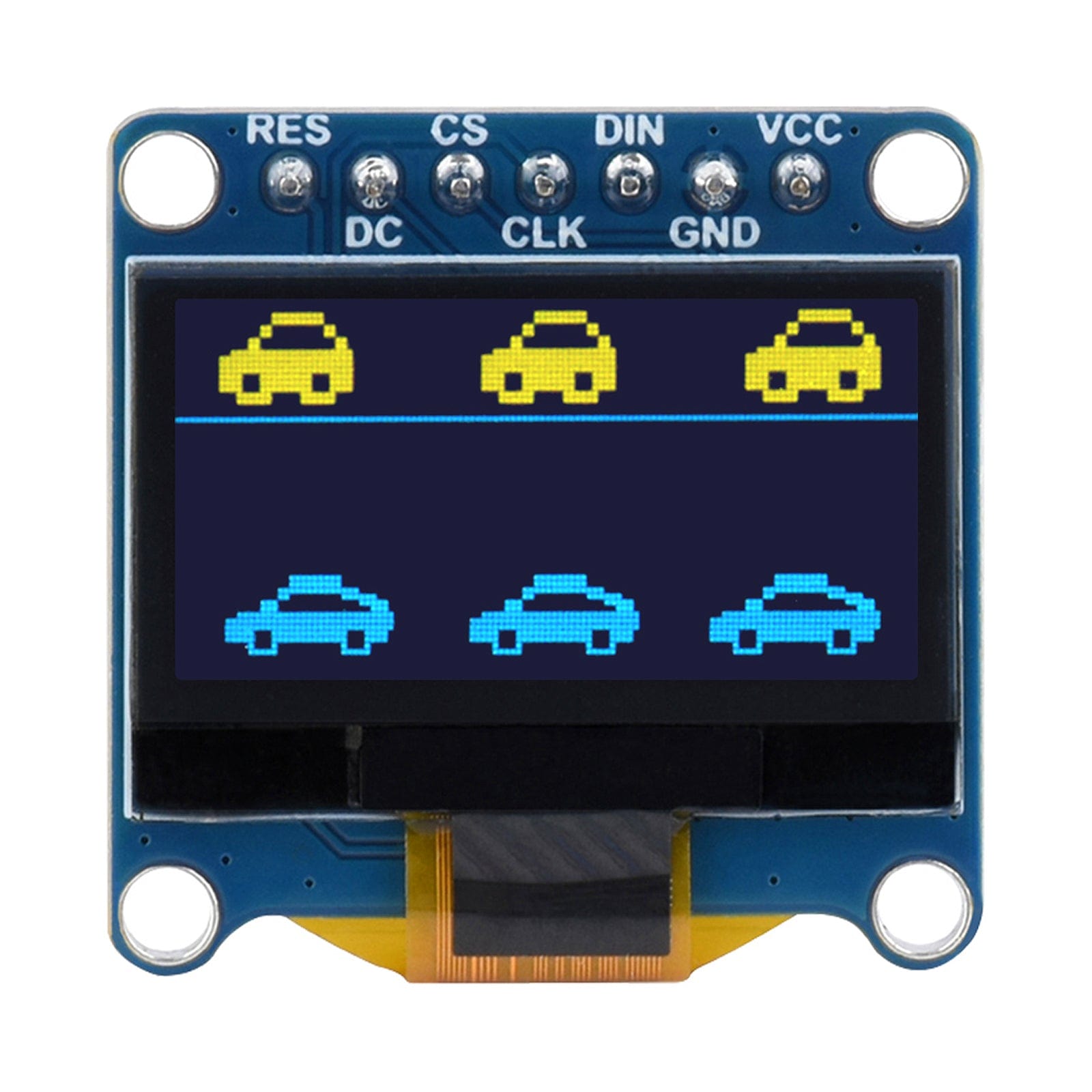
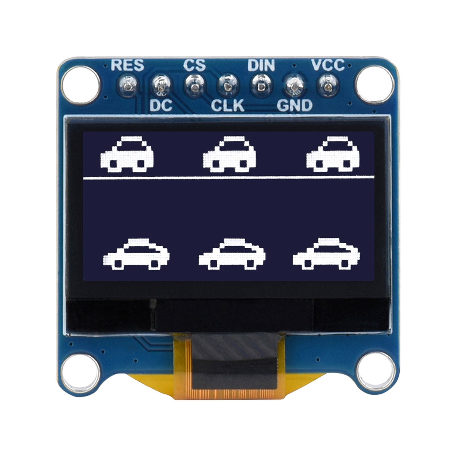
Connecting the display
These displays are supplied with connection cables with a block at one end and single female connectors at the other. Insert the block onto the pins at the rear of the display so that the RED wire is on the VCC pin. The WHITE wire should then be connected to RES (reset).
We can connect the other ends in several different positions on the Pico’s pins. Initially we will use GP16 to GP20, as they are easy to locate. Here is a map of where to wire the pins:
| Wire colour | GPIO Pin # | Name |
| White | 16 | RST reset |
| Orange | 17 | CS – Chip select |
| Yellow | 18 | CLK - Clock |
| Blue | 19 | MOSI / DIN |
| Green | 20 | DC – Data/Command |
| Red | 3.3 Volts | VCC |
| Black | GND | GND |
Pico SPI OLED Test program
The program below will test that everything is working properly. When executed it should light up the display with text and print a line to the Shell window in Thonny, like this:
After copying and trying the code, read on to learn about how it works:
# Waveshare 0.96inch OLED Module via SPI (SSD1315)
# Available in White, Blue or Yellow & Blue
# Tony Goodhew 2 June 2023 - for thepihut.com

# Connect Red to 3.3V and Black to GND
from machine import Pin, SPI
import ssd1306

# Uses SPI port 0
spi_port = 0
MOSI = 19     # blue
CLK = 18      # yellow
CS = 17       # orange
RST = 16      # white   #NB MISO not used
DC = 20       # green

WIDTH = 128
HEIGHT = 64

spi = SPI(
    spi_port,
    baudrate=40000000,
    mosi=Pin(MOSI),
    sck=Pin(CLK))
print(spi) # Not essential - comment out

oled = ssd1306.SSD1306_SPI(WIDTH,HEIGHT,
    spi,
    dc=Pin(DC),
    res=Pin(RST),
    cs=Pin(CS),
    external_vcc=False
    )

# Clear the oled display in case it has junk on it.
oled.fill(0)

# Add some text
oled.text("Pi Pico with", 5, 6, 1)
oled.text('WS 0.96" OLED', 5, 16, 1)
oled.text("SSD1315 SPI", 5, 25, 1)
oled.text('White, Blue or', 5, 36, 1)
oled.text('Yellow & Blue', 5, 46, 1)
oled.text("thepihut.com", 5, 57, 1)

# Finally update the oled display so the text is displayed
oled.show()
How it works
This program gives us some information about the connection. There are two SPI ports on the Pico, 0 and 1, distributed over several different sets of GPIO pins. Here we are using SPI port 0.
It states that this port, in this position, normally uses GP16 for MISO (main in, subnode out). Since this is a display, it only receives data from the Pico (main) and does not send any data from the display (sub node) to the Pico.
We have also used GP16 for reset. We used GP16 for reset so as not to waste it. We could have used any other GPIO pin.
Code Breakdown
This section imports the essential libraries and sets up constants for the connection and the size of the display – 128 pixels wide and 64 pixels high:
from machine import Pin, SPI
import ssd1306

# Uses SPI port 0
spi_port = 0
MOSI = 19     # blue
CLK = 18      # yellow
CS = 17       # orange
RST = 16      # white   #NB MISO not used
DC = 20       # green

WIDTH = 128
HEIGHT = 64
This section sets up the SPI port and the display, which we have called oled:
spi = SPI(
    spi_port,
    baudrate=40000000,
    mosi=Pin(MOSI),
    sck=Pin(CLK))
print(spi) # Not essential - comment out

oled = ssd1306.SSD1306_SPI(WIDTH,HEIGHT,
    spi,
    dc=Pin(DC),
    res=Pin(RST),
    cs=Pin(CS),
    external_vcc=False
    )
The final section below clears the display using oled.fill(0), prints several lines of text and forces the display to show the changes we have made to the screen using oled.show(). Read on for more on this last section.
# Clear the oled display in case it has junk on it.
oled.fill(0)

# Add some text
oled.text("Pi Pico with", 5, 6, 1)
oled.text('WS 0.96" OLED', 5, 16, 1)
oled.text("SSD1315 SPI", 5, 25, 1)
oled.text('White, Blue or', 5, 36, 1)
oled.text('Yellow & Blue', 5, 46, 1)
oled.text("thepihut.com", 5, 57, 1)

# Finally update the oled display so the text is displayed
oled.show()
The pixel at the top left of the screen has coordinate (0, 0) x = 0 and y = 0. The pixel at the top right is at (0, 127). The pixel at the bottom right is (127, 63).
The instruction oled.fill(0) fills the screen with BLACK pixels. Colour 0 represents BLACK while colour 1 represents WHITE (or the colour of your specific screen, white, blue or yellow). If you replace the 0 with 1 it will fill the screen with ‘white’.
The instruction oled.text("Pi Pico with", 5, 6, 1) writes the text within the quotation marks in ‘white’, starting at position (5, 6). Change the final 1 to a 0 and it will write with black pixels which will only show up on a ‘white’ background.
The line oled.text('WS 0.96" OLED', 5, 16, 1) demonstrates how to include quotation marks within the text string which is placed at position x = 5 and y = 16.
The final oled.show() is essential! It tells the display board to update the screen. If you leave it out nothing will appear on the screen. Leaving out this instruction is the most common reason something does not appear.
Extra example - moving text
The following program demonstrates moving black text on a bright background. The connections have been moved to demonstrate a different position on the GPIO pins.
# Waveshare 0.96inch OLED Module(C) via SPI (SSD1315)
# Moving name
# Tony Goodhew 5th July 2023

from machine import Pin, SPI
import ssd1306
import time

# Uses SPI port 0
MOSI = 3     # blue
CLK = 2      # yellow
CS = 1       # orange
RST = 0      # white
DC = 4       # green
spi_port = 0
WIDTH = 128
HEIGHT = 64

spi = SPI(
    spi_port,
    baudrate=40000000,
    mosi=Pin(MOSI),
    sck=Pin(CLK))
print(spi)

oled = ssd1306.SSD1306_SPI(WIDTH,HEIGHT,
    spi,
    dc=Pin(DC),
    res=Pin(RST),
    cs=Pin(CS),
    external_vcc=False
    )

for x in range(64):
    oled.fill(1)
    oled.text("Pico", int(x*1.5), x, 0)
    oled.show()
    time.sleep(0.1)

oled.fill(0)
oled.show()
That's all for today folks, more tutorials from Tony coming soon!
About the Author
This article was written by Tony Goodhew. Tony is a retired teacher of computing who starting writing code back in 1968 when it was called programming - he started with FORTRAN IV on an IBM 1130! An active Raspberry Pi community member, his main interests now are coding in MicroPython, travelling and photography.


5 comments
Dan
If your screen is not working, look on the back of the scree on the pin side. They will normally say what address select they are. I code a bit different than this example as it is easier for me to follow and debug later. When you introduce your display, you need to introduce the address as well as follows:
from machine import Pin,I2C
from ssd1306 import SSD1306_I2C
import time
i2c=I2C,scl=Pin(17),freq=400000)
oled=SSD1306_I2C(128,64,i2c,addr=0×3c)
ian
also, the scrolling example does appear to do anything – it runs from Thonny, but display does not update. basic example seems fine.
also, the scrolling example does appear to do anything – it runs from Thonny, but display does not update. basic example seems fine.
ian
I have 2 of these displays and the displays did nothing. Seems like poor connections on some pins. CS pin
issue possibly. holding the connector down and it works – mostly!
I have 2 of these displays and the displays did nothing. Seems like poor connections on some pins. CS pin
issue possibly. holding the connector down and it works – mostly!
Edward Hanson
A very useful guide. Easy to follow and the explanation of the code was great. I have now managed to programme my Pico to display data from a sensor and figured out how to display simple bar graphs for the data using the rectangle fill and a bit of simple maths.
A very useful guide. Easy to follow and the explanation of the code was great. I have now managed to programme my Pico to display data from a sensor and figured out how to display simple bar graphs for the data using the rectangle fill and a bit of simple maths.
Peter West
A very handy guide to using the SSD1306 via its SPI interface. Up to now have only used one with an I2C interface
A very handy guide to using the SSD1306 via its SPI interface. Up to now have only used one with an I2C interface