

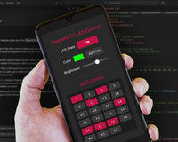
Let it Glow Maker Advent Calendar Day #12: Dazzling Displays!
It’s the final day of the Let it Glow Maker Advent Calendar!
Today we're playing with a Liquid-Crystal Display (LCD), which is a bit of a hybrid as it has an LED backlight (kinda blinky) and can also show information from our program - which makes it double the fun.
It's another component that's hugely popular with makers around the world because of how useful they are as a project display interface to show data and build into projects.
Let’s get it set up!
Box #12 Contents
In this box you will find:
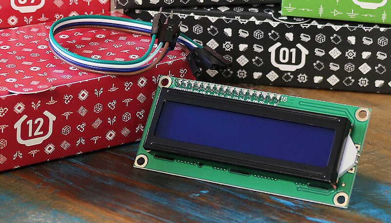
- 1x 16x2 LCD (with I2C backpack)
- 4x Male to female jumper wires
Important: The rear of the LCD should have a 2-pin header with a little black jumper/joiner already fitted to them. If not, check your bag for this and pop it on the 2-pin header.
Today’s Project
Today we’re going to show you how to wire the LCD up, then take you through the library to show you all of the functions you can use to show different data and characters on them.
We'll bring that to life with some fun projects, and then it's over to you to make...whatever you want!
First, let's talk about the display...
What is an LCD?
In your box is an LCD - a Liquid-Crystal Display.
You may have seen displays like these on various terminals and machines on your travels. They're not as common as they used to be as the world continues to switch to little touchscreens for devices, but they're still perfect for maker projects!
We won't get into how the liquid crystals in these displays work or how they show characters, that's heavy stuff and a complete lesson in itself, just know this - it all started with carrots in 1888!
Backpacks make life easier
You'll notice the front of the LCD has lots of pins, sixteen in fact. Traditionally you'd need to wire up most of those pins to your microcontroller which was a bit of a fiddly task, however the LCD in your box includes an I2C backpack.
These backpacks connect to the LCD pins and provide us with a (much easier) I2C interface to control them with. The backpack allows us to connect the LCD to our Pico with just four pins!
Construct the Circuit
As always, make sure your Pico is disconnected from the USB cable when working on the circuit.
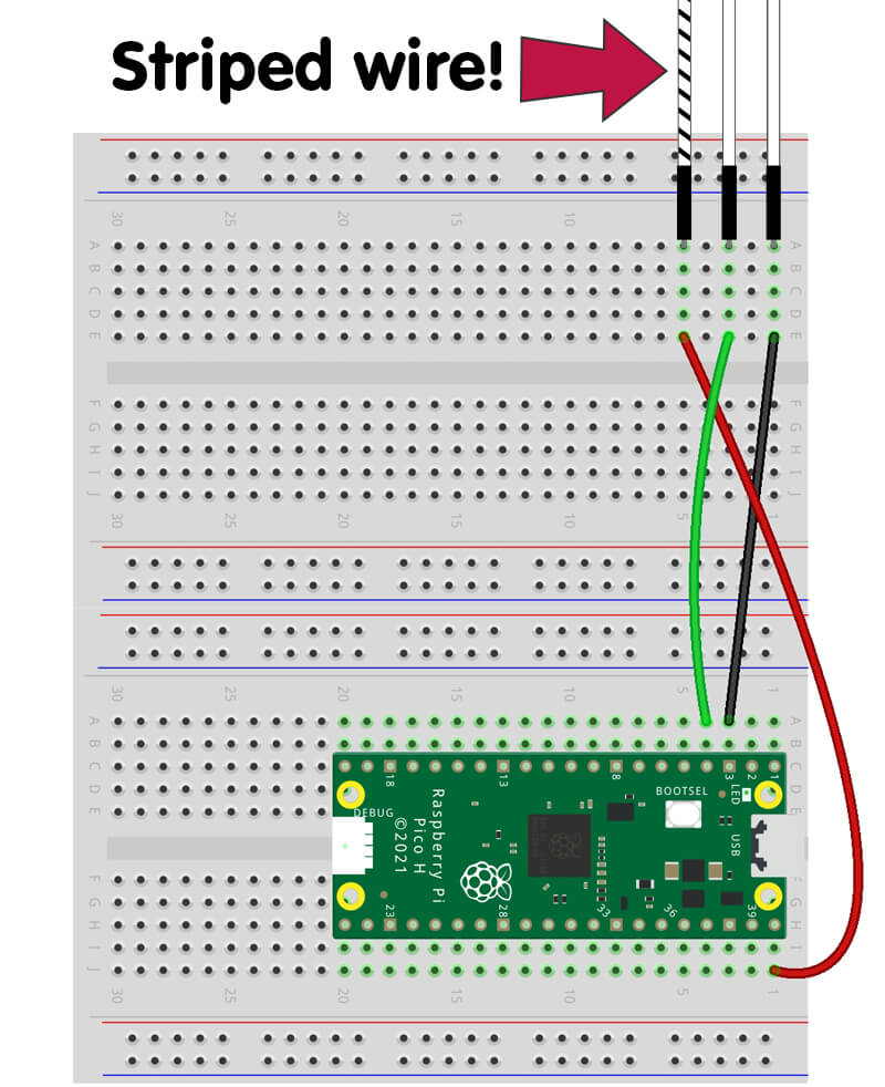
Prepare the breadboard
Remove the membrane keypad and block LED from yesterday, but keep the RGB LED strand in place.
Your starting point should look like this:
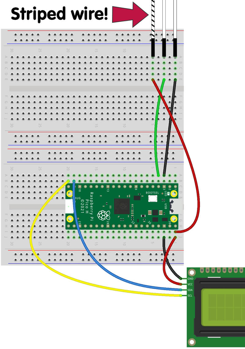
Connect the LCD
Today you have a different set of jumper wires, male to female. We're going to plug the female ends into the LCD backpack, and the male ends into our breadboard. It's usually best to separate the wires to allow them to easily reach the pins we mention below.
We have four pins to connect, GND, VCC (5V), SDA and SCL. These are labelled on the rear of the display which is handy for double-checking where wires are going.
The two pins on the other side of the backpack should have a little black header/joiner on them. This just enables the backlight LED. If that little black jumper is in your bag and not connected, pop it on those two pins now.
Let's get to it - the Pico pinout is here if you need it:
- Connect GND on the LCD to a GND pin on the Pico. We're using physical pin 38
- Connect the VCC pin to the 5V VBUS pin (physical pin 40). We're using this pin for the strand lights already, but there are two available holes you can use (or make a rail if you prefer)
- Connect the SDA pin to GPIO14 (physical pin 19). This will be shared with the temperature sensor (there are two available holes next to that pin on your breadboard)
- Connect the SCL pin to GPIO15 (physical pin 20). Again, this will be shared with the temperature sensor
Here's how things should look so far:
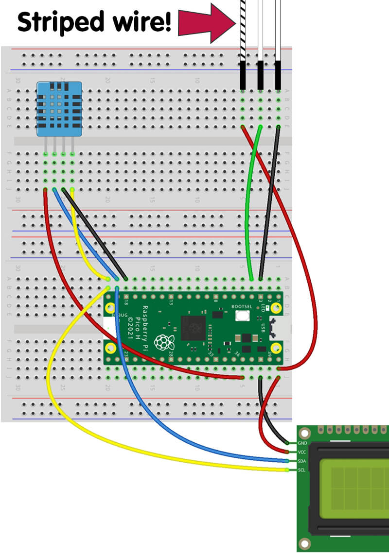
Connect the temperature sensor
We'll fit our temperature sensor to the top-left of our breadboard, with the waffle side facing forward the same as day #9.
Let's wire it up, left to right:
- Connect the first pin (left) to the 3V3 pin (physical pin 36)
- Connect the second pin to GPIO14 (physical pin 19). This is shared with the LCD.
- Connect the third pin to GND. We're using physical pin 18.
- Connect the fourth pin to GPIO15 (physical pin 20)
We really recommend triple-checking everything! Here's what your completed circuit should look like:
Install the code library
Just like day #9 with the temperature sensor, we need to install a code library to use this display. This time it requires us to install two files to our Pico, but it's the same process.
We're going to be using the excellent RPI-PICO-I2C-LCD library by GitHub user T-622 (Tyler Peppy). This library adapts code from another LCD library to make it all work nicely on a Pico. Marvellous!
So, on with our two library files. As the library code is rather long, we'll be directing you to pages containing the raw versions of the code to copy and paste into Thonny.
File #1 - lcd_api.py
Go to the following link to open the raw code for this library file. Once there, use Ctrl+A to select all of it, Ctrl+C to copy it, then go back to Thonny and paste it in a new tab (Ctrl+V):
https://raw.githubusercontent.com/T-622/RPI-PICO-I2C-LCD/main/lcd_api.py
Save the file on your Pico (File > Save As) as lcd_api.py then close that tab.
File #2 - pico_i2c_lcd.py
Now go to this link and do the same - use Ctrl+A to select all of it, Ctrl+C to copy it, then go back to Thonny and paste it in a new tab (Ctrl+V):
https://raw.githubusercontent.com/T-622/RPI-PICO-I2C-LCD/main/pico_i2c_lcd.py
Save the file on your Pico (File > Save As) as pico_i2c_lcd.py then close that tab.
Close the library files
Important! As before, once you've saved both library files to your Pico, close the script tab down by selecting the 'X' on the tab!
Before we start coding...
"...Have you tried turning it off and on again?"
Our circuit uses two I2C devices - the temperature sensor and the display - on the same I2C bus (more on this later).
We found that, very rarely, we need to unplug our Pico's USB cable and plug it back in again to get it to find both I2C devices/addresses properly without showing an error message ("EIO" or "bad pin"). Most of the time it doesn't happen, but if it does, now you know what to do!
If you run into any issues at any stage, double-check your wiring first, then disconnect your Pico from the USB port, leave it a few seconds then plug it back in.
Activity #1: Test program & tweaks
We need to make sure everything is wired up and working as expected, so let's push some simple text to the LCD and ensure the display is set up properly.
This script simply shows "Hello, world!" on the first row of the LCD whilst printing text in the shell window.
Unlike other days, we're not going to go into how the code is doing this (yet) - we'll cover that in the next activity. This one is purely to get our LCDs ready to play with.
Setting the contrast
One of the main reasons we're running this first test is to allow us to check, and adjust, the display's contrast.
On the rear of the display is a little blue square with a cross in the middle. That's a small potentiometer which we may (or may not) need to adjust to allow us to see the characters on the display.
Run the script below, check that Thonny is showing a print line ("Display is now showing characters") then check the front of your LCD for "Hello, World!" on the first row.
No text?
If you don't see any text, or see lots of white squares, use a small screwdriver to gently adjust the potentiometer (usually clockwise) a very small amount at a time.
The potentiometer is delicate and does not keep rotating - it will stop at both ends of its range, so please don't force it!
Here's the test code:
from machine import I2C
from lcd_api import LcdApi
from pico_i2c_lcd import I2cLcd

# Define LCD I2C pins/BUS/address
SDA = 14
SCL = 15
I2C_BUS = 1
LCD_ADDR = 0x27

# Define LCD rows/columns
LCD_NUM_ROWS = 2
LCD_NUM_COLS = 16

# Set up LCD I2C
lcdi2c = I2C(I2C_BUS, sda=machine.Pin(SDA), scl=machine.Pin(SCL), freq=400000)
lcd = I2cLcd(lcdi2c, LCD_ADDR, LCD_NUM_ROWS, LCD_NUM_COLS)

# Show a string on the LCD
lcd.putstr("Hello, World!")

print("*********************************")
print("Display is now showing characters")
print("*********************************")
Activity #2: The everything script!
Time to explain how to use this library with the LCD, and we're going to do things a bit backwards this time, running the code before we explain how it works.
The library comes with a test file showing its capabilities, however we wanted to break it down a little, space things out and add lots of excessive commentary to give you something super-duper clear that you can almost refer back to as a guide.
Grab the example code below then run it in Thonny a few times whilst trying to follow the commentary, then we'll explain each part in a moment:
from machine import I2C, Pin
from lcd_api import LcdApi
from pico_i2c_lcd import I2cLcd
import time

# Define LCD I2C pins/BUS/address
SDA = 14
SCL = 15
I2C_BUS = 1
LCD_ADDR = 0x27

# Define LCD rows/columns
LCD_NUM_ROWS = 2
LCD_NUM_COLS = 16

lcdi2c = I2C(I2C_BUS, sda=machine.Pin(SDA), scl=machine.Pin(SCL), freq=400000)
lcd = I2cLcd(lcdi2c, LCD_ADDR, LCD_NUM_ROWS, LCD_NUM_COLS)

# Our variables
mystring = "String variable" # String
myinteger = 44         # Integer
myfloat = 9.445589     # Float

# Just a function to sleep and then clear the LCD
# Saves lines after each example!
def clearLCD():

    time.sleep(3)
    lcd.clear()

##### Example Program Start #####

# This is how you show basic text
lcd.putstr("I am a string")
time.sleep(3)

# This is how you clear the display
# Do this before you send new data to be displayed
lcd.clear()

# This is how you move the cursor
# We moved it to the second row
# 1st number is column (X), 2nd number is row (Y)
# Numbers start at zero
# (0,0) is the 1st column, 1st row
lcd.move_to(0, 1)
lcd.putstr("Second row!")
clearLCD()

# This is how you show a variable
# Variables can be strings, integers or floats
# 'str' converts them to a string
# Here are three examples:
lcd.putstr(str(mystring)) # String
clearLCD()

lcd.putstr(str(myinteger)) # Integer
clearLCD()

lcd.putstr(str(myfloat)) # Float
clearLCD()

# This turns the backlight off
lcd.backlight_off()
clearLCD()

# This turns the backlight on
lcd.backlight_on()
clearLCD()

# This turns the standard cursor on
lcd.show_cursor()
clearLCD()

# This turns the standard cursor off
lcd.hide_cursor()
clearLCD()

# This turns the blinking cursor on
lcd.blink_cursor_on()
clearLCD()

# This turns the blinking cursor on
lcd.blink_cursor_off()
clearLCD()
How the library works
The code above sets the LCD up then runs through lots of the most useful functions that you'll need when making projects. Let's talk you through it.
Library Setup
First we must import the two library files we created:
from lcd_api import LcdApi
from pico_i2c_lcd import I2cLcd
We need to tell our program which I2C pins (SCL/SDA) we're using, as well as which I2C BUS (notice on the Pico pinout the blue I2C pins are either I2C0 or I2C 1? That's the BUS number):
# Define I2C pins/BUS
SDA = 14
SCL = 15
I2C_BUS = 1
Next we tell our program what the LCD's I2C address is (we've found that for you, it's 0x27) followed by the number of rows and columns in our display. This is a 16x2 display (16 columns, 2 rows) so we use 16 and 2:
I2C_ADDR = 0x27
LCD_NUM_ROWS = 2
LCD_NUM_COLS = 16
Then we have some lines setting up our I2C LCD with this information:
lcdi2c = I2C(I2C_BUS, sda=machine.Pin(SDA), scl=machine.Pin(SCL), freq=400000)
lcd = I2cLcd(lcdi2c, LCD_ADDR, LCD_NUM_ROWS, LCD_NUM_COLS)
Library Functions
Let's run through what each of the functions do. All of these are featured in the example script above. The first one is really important!
Important! Clearing the display
When using one of the functions below to show something on the LCD, you should (usually) clear the display first using:
lcd.clear()
If you don't use lcd.clear() before sending the next thing to be shown on the display - it'll show that new data right on top of the old data, and in some scenarios that can leave old characters lurking behind and make a mess of things.
Sending a string
To send a string (some text) to the LCD, we use:
lcd.putstr("I am a string")
Sending a variable
To send your variable to the display we use the following line. Variables can be strings, integers or floats because this line converts them to a string using str first:
lcd.putstr(str(variable_name))
Send a string alongside a variable
This isn't strictly a feature of the library, just a different way of structuring what goes inside those brackets, but as a handy reference we wanted to show you an example of a string next to a variable.
We just use the + operator to join the two together.
Here's a string then a variable:
lcd.putstr("String" + str(variable))
Here's a variable then a string:
lcd.putstr(str(variable) + "String")
Moving the cursor position
By default, any data you send to be displayed is in position 0,0 (first column, first row). Sometimes you'll want to show data in different positions.
To do this we use the line below before we send data. The first number in brackets is the column, and the second number is the row.
Our display is a 16x2 LCD, so we have 16 columns and 2 rows. The numbers start at zero though, so for example, the first column is 0 and the last one is 15. Similarly, the first row is 0, the second row is 1.
Remember, you use this line before using a line to send data, like this:
lcd.move_to(0, 1)
lcd.putstr("Second row")
Turning the backlight off/on
If you want to turn the backlight off, use this line:
lcd.backlight_off()
Turn it back on again with:
lcd.backlight_on()
Show the standard cursor
You can set your program to show a little underline cursor, indicating the current position.
Turn it on with:
lcd.show_cursor()
Turn it off with:
lcd.hide_cursor()
Show the blinking cursor
You can alternatively set your program to show a blinking cursor, indicating the current position.
Turn it on with:
lcd.blink_cursor_on()
Turn it off with:
lcd.blink_cursor_off()
Activity #3: Displaying simple data
Now that we understand the library, let's get into some examples.
Basic counter
We'll start simple by creating a basic counter project. We're going to run a simple for loop with a range of 500 (loop 500 times).
Our for loop will start at 0 and each iteration it will go up by 1. On each iteration, we inject that number (using i) into our LCD code, joining a string "Count: " with the number (i).
We clear the LCD each time, to make way for the new data on the next iteration.
from machine import I2C, Pin
from lcd_api import LcdApi
from pico_i2c_lcd import I2cLcd
import time

# Define LCD I2C pins/BUS/address
SDA = 14
SCL = 15
I2C_BUS = 1
LCD_ADDR = 0x27

# Define LCD rows/columns
LCD_NUM_ROWS = 2
LCD_NUM_COLS = 16

lcdi2c = I2C(I2C_BUS, sda=machine.Pin(SDA), scl=machine.Pin(SCL), freq=400000)
lcd = I2cLcd(lcdi2c, LCD_ADDR, LCD_NUM_ROWS, LCD_NUM_COLS)

for i in range(500):

    lcd.putstr("Count: " + str(i))
    time.sleep(1)
    lcd.clear()
A better basic counter
The example above works, but do you notice the slight flicker of the string "Count: " on each iteration?
That's because we're clearing the entire display each time...but the string is in a static position, so why keep clearing and re-showing it?
In this scenario, we can write "Count: " just once, before the loop starts, and then just push a new number to the display each iteration.
We do this by setting the cursor position to column 7 and writing data from there. This means the "Count: " is left alone and the number updates in the right place every time. It also means we don't need to clear the display each iteration, as the number overwrites the last (in the same position):
from machine import I2C, Pin
from lcd_api import LcdApi
from pico_i2c_lcd import I2cLcd
import time

# Define LCD I2C pins/BUS/address
SDA = 14
SCL = 15
I2C_BUS = 1
LCD_ADDR = 0x27

# Define LCD rows/columns
LCD_NUM_ROWS = 2
LCD_NUM_COLS = 16

lcdi2c = I2C(I2C_BUS, sda=machine.Pin(SDA), scl=machine.Pin(SCL), freq=400000)
lcd = I2cLcd(lcdi2c, LCD_ADDR, LCD_NUM_ROWS, LCD_NUM_COLS)

lcd.putstr("Count: ")

for i in range(500):

    lcd.move_to(7, 0)
    lcd.putstr(str(i))
    time.sleep(1)
Activity #4: Displaying current environment data
Tis' the season to keep an eye on the temperature, so let's do just that by showing data from our temperature sensor on the display. We'll also show the humidity too - neat!
Every 5 seconds we'll grab the data from our sensor, round it to 1 decimal place, then show this data on our display. We'll show some static text to tell us which value is which, then update the values each time our code loops.
We use lcd.putstr(str(round(measurements['t'],1))) to do everything in one line. This is using the temperature reading, rounding it to 1 decimal place, converting that into a string (with str) and pushing it to the LCD. We've seen this kind of thing before in day #9 when we first met our sensor, so it shouldn't be too confusing...right?!
Before you give this a try, we need to mention a limitation of our code...
The cold could break our code!
Our code assumes the temperature will never go down into single digits, because if it did, there would be characters left over from the previous value.
For example, if the temperature was 10.1 (four columns) and went down to 9.9 (three columns), the new 9.9 value would not overwrite the final 1 in 10.1...so you'd see 9.91. We wanted to show you this as a working example of the whole 'clear the LCD' thing to show you why it's so important.
If your environment's temperature could get that low, you may need to alter the code. The easy way would be to simply clear the display and re-write the static strings every time, inside the loop, and accept the flicker. There are lots of other ways you could work around it too.
Two I2C devices at once - is this OK?!
You may notice that we're now running two I2C devices (temperature sensor and LCD) on the same SDA/SCL pins. Does that not cause issues?
Nope - not in this project anyway! Both of our devices are using the same SDA and SCL pins, but as they have different addresses, they can both communicate individually.
When devices come with the same default address (that can't be changed) then you run into issues. But that's for another day...
Here's the code:
from machine import I2C, Pin
from lcd_api import LcdApi
from pico_i2c_lcd import I2cLcd
from dht20 import DHT20
import time

# Define LCD/sensor I2C pins/BUS/address
SDA = 14
SCL = 15
I2C_BUS = 1
LCD_ADDR = 0x27
TEMP_ADDR = 0x38

# Define LCD rows/columns
LCD_NUM_ROWS = 2
LCD_NUM_COLS = 16

# Set up LCD I2C
lcdi2c = I2C(I2C_BUS, sda=machine.Pin(SDA), scl=machine.Pin(SCL), freq=400000)
lcd = I2cLcd(lcdi2c, LCD_ADDR, LCD_NUM_ROWS, LCD_NUM_COLS)

# Set up temperature sensor I2C
tempi2c = I2C(I2C_BUS, sda=SDA, scl=SCL)
dht20 = DHT20(TEMP_ADDR, tempi2c)

# Write static text
lcd.putstr("Temp:")

lcd.move_to(0, 1) # Move to second row
lcd.putstr("Humidity:")

while True:

    # Grab data from the sensor dictionary
    measurements = dht20.measurements

    # Show temp data on the first row
    lcd.move_to(12, 0) # 12th column, 1st row
    lcd.putstr(str(round(measurements['t'],1)))

    # Show humidity data on the second row
    lcd.move_to(12, 1) # 12th column, 2nd row
    lcd.putstr(str(round(measurements['rh'],1)))

    time.sleep(5)
Activity #5: Highest/lowest temperature display
The example above is great for knowing what the current temperature is, but what if we wanted to keep a track of the lowest/highest temperatures that our program has seen since running?
This is easy! All we need to do is create, and maintain/update, variables that save the lowest and highest temperature values.
In the example code below, every time our loop runs we take a temperature reading and show it on the first row of the display. We then use if statements to check if that reading is lower than our lowest recorded temperature, or higher than our highest recorded temperature.
If they are lower/higher, we update that lowest/highest variable with the new value, then write that to the second row of the display.
Give it a try (same warning applies if your environment could go into single digits, you may want to clear the LCD and write the static text on every update):
from machine import I2C, Pin
from lcd_api import LcdApi
from pico_i2c_lcd import I2cLcd
from dht20 import DHT20
import time

# Define LCD/sensor I2C pins/BUS/address
SDA = 14
SCL = 15
I2C_BUS = 1
LCD_ADDR = 0x27
TEMP_ADDR = 0x38

# Define LCD rows/columns
LCD_NUM_ROWS = 2
LCD_NUM_COLS = 16

# Set up LCD I2C
lcdi2c = I2C(I2C_BUS, sda=machine.Pin(SDA), scl=machine.Pin(SCL), freq=400000)
lcd = I2cLcd(lcdi2c, LCD_ADDR, LCD_NUM_ROWS, LCD_NUM_COLS)

# Set up temperature sensor I2C
tempi2c = I2C(I2C_BUS, sda=SDA, scl=SCL)
dht20 = DHT20(TEMP_ADDR, tempi2c)

# Write  static LCD text
lcd.putstr("Current:")
lcd.move_to(0, 1) # Move to second row
lcd.putstr("L:       H:")

#Take initial reading
measurements = dht20.measurements

# Create temp and humidity variables
# From initial readings
lowtemp = round(measurements['t'],1)
hightemp = round(measurements['t'],1)

# Write initial low temp value to LCD
lcd.move_to(3, 1)
lcd.putstr(str(lowtemp))

# Write initial high temp value to LCD
lcd.move_to(12, 1) # 12th column, 2nd row
lcd.putstr(str(hightemp))

while True:

    # Grab data from the sensor dictionary
    measurements = dht20.measurements

    # Create variable for current temp
    tempnow = round(measurements['t'],1)

    # Update current temp on display
    lcd.move_to(12, 0)
    lcd.putstr(str(tempnow))

    # If the lowest temp is HIGHER than current temp
    if tempnow < lowtemp:

        # Update the lowest recorded temp
        lowtemp = tempnow

        # Update the LCD data
        lcd.move_to(3, 1) # 3rd column, 2nd row
        lcd.putstr(str(lowtemp))

    # If the highest temp is LOWER than current temp
    if tempnow > hightemp:

        # Update the highest recorded temp
        hightemp = tempnow

        # Update the LCD data
        lcd.move_to(12, 1) # 12th column, 2nd row
        lcd.putstr(str(hightemp))

    # Check every 5 seconds
    time.sleep(5)
Activity #6: Strand colour display
Let's bring our LED strand back into the code. We're going to run an example that shows the current RGB colour on the display, changing whenever the LED colour changes.
To do this, we're going to make use of a dictionary of colours, as we can use the key to both provide the RGB colour as well as the colour name (text/string) for the display. Handy!
Here's our dictionary called mycolours (feel free to add more):
mycolours ={
    "Red":(255,0,0),
    "Green":(0,255,0),
    "Blue":(0,0,255),
    "White":(255,255,255),
}
We use a for loop to iterate over the dictionary:
for i in mycolours:
Then we use i (which will be the key of the colour, Red for example) for the LED strand fill colour and the LCD text.
The strand.fill references the dictionary, requesting the value associated with the provided key (i):
strand.fill(mycolours[i])
The LCD code can just use i directly, as the key is the name of the colour:
lcd.putstr(str(i))There's only one catch - when you iterate over a dictionary, it's not in order like a list. You can add some code to order things, but it's probably a bit too complicated for your first twelve days (for the curious and brave, look up the sorted() method using lambda!).
Try the example below in the normal way:
from machine import I2C, Pin
from lcd_api import LcdApi
from pico_i2c_lcd import I2cLcd
from neopixel import NeoPixel
import time

# LED details
GPIOnumber = 2
LEDcount = 15

# Define the strand pin number and number of LEDs from variables
strand = NeoPixel(Pin(GPIOnumber), LEDcount)

# Define LCD I2C pins/BUS/address
SDA = 14
SCL = 15
I2C_BUS = 1
LCD_ADDR = 0x27

# Define LCD rows/columns
LCD_NUM_ROWS = 2
LCD_NUM_COLS = 16

# Set up LCD I2C
lcdi2c = I2C(I2C_BUS, sda=machine.Pin(SDA), scl=machine.Pin(SCL), freq=400000)
lcd = I2cLcd(lcdi2c, LCD_ADDR, LCD_NUM_ROWS, LCD_NUM_COLS)

mycolours ={
    "Red":(255,0,0),
    "Green":(0,255,0),
    "Blue":(0,0,255),
    "White":(255,255,255),
}

# Turn off all LEDs before program start
strand.fill((0,0,0))
strand.write()
time.sleep(1)

while True:

    for i in mycolours:

        print(i)

        # Clear the LCD
        lcd.clear()

        # Fill the strand with the current colour
        strand.fill(mycolours[i])
        strand.write()

        # Update display with the key of the colour
        lcd.putstr("Strand colour:")
        lcd.move_to(0, 1) # 2nd row
        lcd.putstr(str(i)) # Show the dictionary key name

        time.sleep(2)
Activity #7: The random colour finder
Are you trying to find some cool RGB colours to use in your code, but you're not sure which RGB values to use?
How about a little program to show a random colour on our LED strand, then display the RGB values on the display for you to take a note of? A neat little program, and another great excuse to use random!
Our code creates random RGB values, pushes them to the LED strand, then displays the individual RGB values on the LCD next to the R, G and B. Easy!
If you need more time to write down the RGB values, just increase the delay at the end of the loop.
Give it a try:
from machine import I2C, Pin
from lcd_api import LcdApi
from pico_i2c_lcd import I2cLcd
from neopixel import NeoPixel
import time
import random

# LED details
GPIOnumber = 2
LEDcount = 15

# Define the strand pin number and number of LEDs from variables
strand = NeoPixel(Pin(GPIOnumber), LEDcount)

# Define LCD I2C pins/BUS/address
SDA = 14
SCL = 15
I2C_BUS = 1
LCD_ADDR = 0x27

# Define LCD rows/columns
LCD_NUM_ROWS = 2
LCD_NUM_COLS = 16

# Set up LCD I2C
lcdi2c = I2C(I2C_BUS, sda=machine.Pin(SDA), scl=machine.Pin(SCL), freq=400000)
lcd = I2cLcd(lcdi2c, LCD_ADDR, LCD_NUM_ROWS, LCD_NUM_COLS)

# Turn off all LEDs before program start
strand.fill((0,0,0))
strand.write()
time.sleep(1)

while True:

    lcd.clear()

    # Add surrounding text
    lcd.putstr("This colour is:")
    lcd.move_to(0, 1)
    lcd.putstr("R:   G    B")

    # Create random RGB values
    r = random.randint(0,255)
    g = random.randint(0,255)
    b = random.randint(0,255)

    # Fill the strand with the current colour
    strand.fill((r,g,b))
    strand.write()

    # Display the RGB values on the LCD
    lcd.move_to(1, 1)
    lcd.putstr(str(r)) # R value

    lcd.move_to(6, 1)
    lcd.putstr(str(g)) # G value

    lcd.move_to(11, 1)
    lcd.putstr(str(b)) # B value

    time.sleep(5)
Activity #8: Scrolling text!
Let's finish with some scrolling text. Making information scroll across the display means you can show longer strings and more data, which can be really handy for some projects!
We manipulate strings to give us the impression of scrolling data. We create a function to do all that hard work for us, then just call that function with our string as the argument.
Before we explain anything in detail, run the code below whilst having a read through the commentary, then carry on reading below for some explanations. We've added a print line as we feel this helps to understand what's going on:
from machine import I2C, Pin
from lcd_api import LcdApi
from pico_i2c_lcd import I2cLcd
import time

# Define LCD I2C pins/BUS/address
SDA = 14
SCL = 15
I2C_BUS = 1
LCD_ADDR = 0x27

# Define LCD rows/columns
LCD_NUM_ROWS = 2
LCD_NUM_COLS = 16

# Set up LCD I2C
lcdi2c = I2C(I2C_BUS, sda=machine.Pin(SDA), scl=machine.Pin(SCL), freq=400000)
lcd = I2cLcd(lcdi2c, LCD_ADDR, LCD_NUM_ROWS, LCD_NUM_COLS)

def ScrollLeft(text):

    # Adds 16 blank spaces after our string
    text = text + (16 * " ")

    while True:

        # Always start each loop at 0,0
        lcd.move_to(0, 0)

        # Show the first 16 characters of the string
        lcd.putstr(text[:16])

        # Scroll speed delay
        time.sleep(0.5)

        # Updates 'text' before the next loop
        # text[1:] removes the first character
        # + text[0] adds the first character to the end
        text = text[1:] + text[0]

        print(text)

# Run our function
ScrollLeft("We have scrolling text!")
Scrolling text summary
Here's how our scrolling function works:
- We give the function a string as an argument
- We add 16 blank spaces (" ") to the end of the string
- We then start a while loop:
- Every loop, we force the display to move back to position 0,0
- We show the first 16 characters of the string on the display
- We add a delay
- We remove the first character of the string and add it to the end using the slice operator (new thing alert, see below!)
At the very end of our example code, outside of the function, we call this function, and add the string we want to display in the brackets (as an argument for the function).
What is a slice operator?
We're using a slice operator to manipulate the string we pass to our function, but what is this?
Slice operators help us chop up strings, taking 'slices' from it and doing things with those slices. We use the string's variable name followed by square brackets [ ] and add different things inside those brackets depending on what we want to do.
Here's a few some examples you can run. We'll make a string called mystring and print it with some slice operators.
Example 1
If we use a number to the right of a colon, it will return that number of characters from the start of a string. Try this:
mystring = "Hello"

print(mystring[:1])
print(mystring[:2])
print(mystring[:3])
The output will be:
H
He
Hel
Example 2
If we use a number to the left of a colon, it will remove that many characters from the start of a string. Try this:
mystring = "Hello"

print(mystring[1:])
print(mystring[2:])
print(mystring[3:])
The output will be:
ello
llo
lo
Example 3
If we just enter a number inside the square brackets, it will return the character from that index of the string. Try this:
mystring = "Hello"

print(mystring[0])
print(mystring[1])
print(mystring[2])
The output will be:
H
e
l
Our slice operator
We use slice operators in this line of our example code:
text = text[1:] + text[0]
This takes the existing text variable, removes the first character with text[1:] and then adds the first character to the end using + text[0].
Questions you might have:
- Why do we add 16 blank spaces?
- If we didn't, when the string scrolls and gets to the last character, it would show the last and first character next to each other
- Watch the print lines as the program runs to see the 'gap' it creates
- Comment out that line and watch the print lines and LCD again
- Why do we manually set the LCD back to 0,0 each loop?
- We're letting the characters overwrite the previous ones without clearing the LCD first.
- If we don't set the position each time, the program would try to write the following loop characters next to the last one
- Comment out the lcd.move_to line to see for yourself
- Why do we remove the first character and add it to the end?
- We remove the first character and then show the updated string on the next loop. This makes it look like the text is scrolling.
- We keep adding that removed character to the end of our string to keep the string showing the same text forever
- Watch the print lines as the program runs to see it in action
- What does the asterisk (*) do in text = text + (16 * " ")?
- This is simply a multiplication operator
- It's 16 x " " - which is a blank space 16 characters long
- We could have used " " but the operator option is cleaner
Day #12 Complete!
LCDs are fun right?! We've shown you the basics on how to use an LCD with the library along with a few little tricks, now it's over to you to come up with cool projects that display data in fun ways.
Recap time! What did we cover on day #12:
- How to wire up an LCD (I2C backpacked)
- Using multiple I2C devices with different addresses
- How to use the LCD library
- When to clear an LCD, and when not to
- Showing sensor data on LCD displays
- The slice operator
- Scrolling LCD text
- Our usual re-use of your newfound knowledge (hello there random!)
Over to you...
That's it folks, it's the end of Let it Glow :( We know many of you wanted this to last the traditional full 25 days, however like the previous year, we wanted this to continue be as affordable and accessible to as many people as possible.
We really hope you've enjoyed following along each day, and we really hope you'll continue your journey as a maker, using your selection of blinky bits and other components to experiment making fun projects with.
We've covered the basics of what's possible with this fantastic little microcontroller and the components you've discovered over the last twelve days - but there's so much more to learn and experience!
If you would like to expand your selection of components for the Pico, the store is full of goodies - be sure to check out our dedicated Raspberry Pi Pico section too! Maybe you'll progress on to a Pico W with wireless capabilities?
More Resources
The internet is jam-packed full of projects and examples using the Raspberry Pi Pico and MicroPython, and 99.9% of this information is free - so don't stop now! We've even had some great examples from makers in the comments sections of the calendar along the way (Giles is doing some really cool stuff, check it out!).
Search Engines are your best friend when it comes to making and coding. Forums, blogs, tutorials, social network user groups and more are at your fingertips and hold and endless amount of examples, code snippets, previous discussions and useful information.
A good starting place for inspiration and a great community is the Raspberry Pi forum, specifically the Pico section. Just don't forget to always search before asking a question!
That's all Folks!
Have a Merry Blinkmas and a Blinky New Year, from everyone at The Pi Hut!
We used Fritzing to create the breadboard wiring diagram images for this page.

40 comments
The Pi Hut
@Patrick @Thor @JP Cluchey – Yes, it seems some GBR/GRB strips have made it into the batches for day #10. Sorry about this – luckily an easy fix as you have discovered, just swap the value positions around.
@Patrick @Thor @JP Cluchey – Yes, it seems some GBR/GRB strips have made it into the batches for day #10. Sorry about this – luckily an easy fix as you have discovered, just swap the value positions around.
JP Cluchey
Hi I just worked through this exercise and have some observations. First, the whole kit is extremely well set up. Congrats to the author(s). Second, the LED string I received in the day 12 box was not RGB but GRB. No real issue, but getting corresponding colour outputs required some program modifications. Final note : I had the TIMEDOUT issue until I realised I had placed the the temperature sensor back to front compared to the wiring images. This is easy to do if you don’t pay attention to which face is smooth versus ribbed.
Hi I just worked through this exercise and have some observations. First, the whole kit is extremely well set up. Congrats to the author(s). Second, the LED string I received in the day 12 box was not RGB but GRB. No real issue, but getting corresponding colour outputs required some program modifications. Final note : I had the TIMEDOUT issue until I realised I had placed the the temperature sensor back to front compared to the wiring images. This is easy to do if you don’t pay attention to which face is smooth versus ribbed.
Thor
Interesting – the activity showing colour on the strip and printing the colour on screen is wrong. White=White, Blue=Red, Red=Green and Green=Blue
2025 strip != 2024 strip ?
Interesting – the activity showing colour on the strip and printing the colour on screen is wrong. White=White, Blue=Red, Red=Green and Green=Blue
2025 strip != 2024 strip ?
armando de loyola
hello i have a error message in act. 1 :
Traceback (most recent call last):
File “”, line 17, in
File “pico_i2c_lcd.py”, line 22, in init
OSError: [Errno 5] EIO
i tried turning it on and off again and it still doesnt work
hello i have a error message in act. 1 :
Traceback (most recent call last):
File “”, line 17, in
File “pico_i2c_lcd.py”, line 22, in init
OSError: [Errno 5] EIO
i tried turning it on and off again and it still doesnt work
Patrick
As I reported re box #10, my LED string is not RGB but GBR, so I had to rewrite the dictionary in Activity #6 and do some recoding at #7. I managed, though, so that’s OK :)
As I reported re box #10, my LED string is not RGB but GBR, so I had to rewrite the dictionary in Activity #6 and do some recoding at #7. I managed, though, so that’s OK :)
Alex
I cant get anything to work i keep getting the error
Traceback (most recent call last):
File “”, line 19, in
File “pico_i2c_lcd.py”, line 22, in init
OSError: [Errno 5] EIO
i have attempted other fixes in the comments but none seem to work.
Any help would be nice.
Thanks
I cant get anything to work i keep getting the error
Traceback (most recent call last):
File “”, line 19, in
File “pico_i2c_lcd.py”, line 22, in init
OSError: [Errno 5] EIO
i have attempted other fixes in the comments but none seem to work.
Any help would be nice.
Thanks
Thomas
Made a Good Morning Summary
ImportsHere’s The Code:
from machine import Pin, I2C
from pico_i2c_lcd import I2cLcd
import time Set up the button pin and configure it as an input with a pull-down resistor
redbutton = Pin(3, Pin.IN, Pin.PULL_DOWN) Define LCD I2C pins/BUS/address
SDA = 14
SCL = 15
I2C_BUS = 1
LCD_ADDR = 0×27 Define LCD rows/columns
LCD_NUM_ROWS = 2
LCD_NUM_COLS = 16 Set up the I2C bus and LCD
lcdi2c = I2C, scl=Pin(SCL), freq=400000)
lcd = I2cLcd(lcdi2c, LCD_ADDR, LCD_NUM_ROWS, LCD_NUM_COLS) Function to simulate getting temperature and humidity (replace with actual sensor code)
def get_temperature_and_humidity(): Simulated data, replace with actual sensor readings
temperature = 22.5 # Example temperature in Celsius
humidity = 60 # Example humidity in percentage
return temperature, humidity Function to get the current time (using a simulated time for now)
def get_current_time(): Simulate current time as HH:MM
current_time = time.localtime()
return “{:02}:{:02}”.format(current_time3, current_time4) Function to turn the backlight on
def backlight_on():
lcd.backlight_on() Function to turn the backlight off
def backlight_off():
lcd.backlight_off() Function to set the greeting based on the time of day
def get_greeting():
current_time = time.localtime()
if current_time3 >= 12:
return “Good Afternoon,” # If it’s after 12 PM, display Good Afternoon
else:
return “Good Morning,” # Otherwise, display Good Morning Main loop
while True: Check if the red button is pressed
if redbutton.value() == 1: # If the red button is pressed
print(“Red button pressed”) Clear the LCD
lcd.clear() Turn the backlight on when the button is pressed
backlight_on() First screen: Display greeting based on time of day
greeting = get_greeting()
lcd.putstr(greeting)
lcd.move_to(0, 1) # Move to the second line
lcd.putstr(“Thomas!”)
time.sleep(3) # Wait for 3 seconds Second screen: Time and Temperature
lcd.clear()
current_time = get_current_time()
temperature, humidity = get_temperature_and_humidity() lcd.putstr(“Time: {}”.format(current_time)) lcd.move_to(0, 1) # Move to the second line lcd.putstr(“Temp: {:.1f}C”.format(temperature)) time.sleep(3) # Wait for 3 seconds Third screen: Humidity and Goodbye message
lcd.clear()
lcd.putstr(“Humidity: {}%”.format(humidity))
lcd.move_to(0, 1) # Move to the second line
lcd.putstr(“Goodbye!”)
time.sleep(3) # Wait for 3 seconds Turn off the backlight after showing the goodbye message
backlight_off() time.sleep(0.2) # Short delay for button debouncing
The Pi Hut
@mike – That would suggest that you haven’t added the lcd_api library to your Pico – sometimes people forget to close the tab, overwriting the library and causing all sorts of trouble.
This is the section that created the library and saved it to the Pico:
Go to the following link to open the raw code for this library file. Once there, use Ctrl+A to select all of it, Ctrl+C to copy it, then go back to Thonny and paste it in a new tab (Ctrl+V):
https://raw.githubusercontent.com/T-622/RPI-PICO-I2C-LCD/main/lcd_api.py
Save the file on your Pico (File > Save As) as lcd_api.py then close that tab.
mike
I am having issues with Activity #1 with the following error:
MPY: soft reboot
Traceback (most recent call last):
File “”, line 2, in
ImportError: no module named ‘lcd_api’
when i click to be brought to the script it highlights line 2 of this group:
1 from machine import I2C
2 from lcd_api import LcdApi
3 from pico_i2c_lcd import I2cLcd
Em
I’m having problems with activities 6 & 7 on day 12. The error message I’m getting is quite long so the TL:DR is “problem with Thonny back end. Exception while handling ‘on’”. It occurs when I run the code, it does what is requested for a second before completely shutting down and restarting my pi. I’ve triple checked the wires and copying/pasting the code over from the guide. I noticed from the guide that it says in some points that you can use one of two holes (if one is in use, use the next one) and have tried both with the same issue. Activities 1-5 and activity 8 run fine with no problems. Any idea on how I can fix it?
I’m having problems with activities 6 & 7 on day 12. The error message I’m getting is quite long so the TL:DR is “problem with Thonny back end. Exception while handling ‘on’”. It occurs when I run the code, it does what is requested for a second before completely shutting down and restarting my pi. I’ve triple checked the wires and copying/pasting the code over from the guide. I noticed from the guide that it says in some points that you can use one of two holes (if one is in use, use the next one) and have tried both with the same issue. Activities 1-5 and activity 8 run fine with no problems. Any idea on how I can fix it?
Simon Craig
Hi,
I really enjoyed all of this tutorial.
As it is an annual thing and may change for next year, is there a hard copy available that can be referred back to?
Cheers :D
Hi,
I really enjoyed all of this tutorial.
As it is an annual thing and may change for next year, is there a hard copy available that can be referred back to?
Cheers :D
Luke R
thanks for a fun 12 days, all done now!
thanks for a fun 12 days, all done now!
Guy
Hi Pi Hut,
I just submitted a comment asking for help with an error message, but we realised that we connected the LCD backwards! 🙄 Sorry for not triple checking before writing the previous comment.
Hi Pi Hut,
I just submitted a comment asking for help with an error message, but we realised that we connected the LCD backwards! 🙄 Sorry for not triple checking before writing the previous comment.
Guy
Hi Pi Hut,
We are getting the same error message in the shell as Chris has been:
MPY: soft reboot
Traceback (most recent call last):
File “”, line 19, in
File “pico_i2c_lcd.py”, line 22, in init
OSError: [Errno 110] ETIMEDOUT
>>>
We tried adding the time.sleep command however, no progress has been made. These are our lines, 17 – 20:
lcdi2c = I2C, scl=machine.Pin(SCL), freq=400000)
time.sleep(5)
lcd = I2cLcd(lcdi2c, LCD_ADDR, LCD_NUM_ROWS, LCD_NUM_COLS)
time.sleep(5)
We would really appreciate any suggestions!
Simon G
I have really enjoyed this. I missed last year’s so this was my first advent box. I had a lot of fun completing task and it was also fun to extend the code a little, each day. I have one suggestion: can you either link to the datasheets for the parts, if they’re available, or at least provide the part number so we can look them up, please. I would like to have been able to read up about the RGB LED early on, and I would like to have been able to look up the character set for the LCD display. I did code a loop to display all the characters above 127 so that I could find a degree symbol but a table would be more to inspire something, I think. Anyway, thanks to all involved: I will definitely be ordering one next Christmas.
I have really enjoyed this. I missed last year’s so this was my first advent box. I had a lot of fun completing task and it was also fun to extend the code a little, each day. I have one suggestion: can you either link to the datasheets for the parts, if they’re available, or at least provide the part number so we can look them up, please. I would like to have been able to read up about the RGB LED early on, and I would like to have been able to look up the character set for the LCD display. I did code a loop to display all the characters above 127 so that I could find a degree symbol but a table would be more to inspire something, I think. Anyway, thanks to all involved: I will definitely be ordering one next Christmas.
The Pi Hut
@Chris – Try adding a time.sleep(1) after the I2C setup lines, that might solve it (try a single sleep after both lines, and if that doesn’t work, try a sleep after each I2C device). Sometimes I2C needs a short delay or it falls over, but we haven’t seen that issue recently.
@Chris – Try adding a time.sleep(1) after the I2C setup lines, that might solve it (try a single sleep after both lines, and if that doesn’t work, try a sleep after each I2C device). Sometimes I2C needs a short delay or it falls over, but we haven’t seen that issue recently.
Chris
Help on Day 12 please.
I am getting this error. I have triple checked everything but cannot progress past this. Any advice gratefully received.
Traceback (most recent call last):
File “”, line 17, in
File “pico_i2c_lcd.py”, line 22, in init
OSError: [Errno 110] ETIMEDOUT
Help on Day 12 please.
I am getting this error. I have triple checked everything but cannot progress past this. Any advice gratefully received.
Traceback (most recent call last):
File “”, line 17, in
File “pico_i2c_lcd.py”, line 22, in init
OSError: [Errno 110] ETIMEDOUT
The Pi Hut
@James Gavin – That’s odd, the activities/LEDs should not have caused that. Have you tried unplugging the Pico for a few seconds and starting over (with a different USB port perhaps)? If still no joy, please send us a message via support.thepihut.com and we’ll help with that.
@James Gavin – That’s odd, the activities/LEDs should not have caused that. Have you tried unplugging the Pico for a few seconds and starting over (with a different USB port perhaps)? If still no joy, please send us a message via support.thepihut.com and we’ll help with that.
Radosław
Thank you for the amazing 24 days <3
Thank you for the amazing 24 days <3
James Gavin
Unfortunately, having run through the previous eleven days without issue, this exercise seems to have left me with a fried pi.
Unfortunately, having run through the previous eleven days without issue, this exercise seems to have left me with a fried pi.
Adrian
May I add my thanks to the PiHut team. I started a bit late so I have the advantage of the helpful comments of others to put me right when I was stumped. RT*M more carefully. Will you be doing another one next year? I hope so. Happy Christmas.
May I add my thanks to the PiHut team. I started a bit late so I have the advantage of the helpful comments of others to put me right when I was stumped. RT*M more carefully. Will you be doing another one next year? I hope so. Happy Christmas.
The Pi Hut
@David Brain – Hmm odd that the backlight control is working (suggests correct GPIO pins used) but nothing on the display. Very much points to the potentiometer setting however you mention you’ve tried turning it both ways. Are you seeing the print line in Thonny during the test? If so, we’re stumped, so it might be a faulty unit – please get in touch with support via support.thepihut.com and we’ll help with that.
@David Brain – Hmm odd that the backlight control is working (suggests correct GPIO pins used) but nothing on the display. Very much points to the potentiometer setting however you mention you’ve tried turning it both ways. Are you seeing the print line in Thonny during the test? If so, we’re stumped, so it might be a faulty unit – please get in touch with support via support.thepihut.com and we’ll help with that.
David Brain
V. late to this last day!
Unfortunately, my LCD display just seems to flash when I run the first test. I can get the “backlight” to turn on and off, and the red LED on the back is on.
But I’ve turned the blue potentiometer thing all the way in both directions and can’t see anything on the screen at all; it’s just a bright blue glow. :(
Jim
I have enjoyed following along with these tutorials, already looking forward to next years pack.
I have enjoyed following along with these tutorials, already looking forward to next years pack.
Chris
As a newbie to using a Raspberry Pi Pico I’ve really enjoying the Advent Calendar.
However I’ve got stuck on Day 12 with the message below and would be extremely grateful if anyone can help me sort it out? Thanks Chris
Traceback (most recent call last):
File “”, line 2, in
File “lcd_api.py”, line 2, in
ImportError: can’t import name LcdApi
Scanlen R
I am also getting thiss error:
Traceback (most recent call last):
File “”, line 19
SyntaxError: invalid syntax
referring to the line SDA = 14
I am also getting thiss error:
Traceback (most recent call last):
File “”, line 19
SyntaxError: invalid syntax
referring to the line SDA = 14
Scanlen R
I love this kit.
I am however having an error on the last day.
When i try the supplied code, I get the error message:
from machine import I2C, Pin
from time import sleep
from pico_i2c_lcd import I2cLcd
Can someone help please?
I love this kit.
I am however having an error on the last day.
When i try the supplied code, I get the error message:
from machine import I2C, Pin
from time import sleep
from pico_i2c_lcd import I2cLcd
Can someone help please?
Vife
Love the new calendar even better than last year which was very fun and X-mas oriented with song and lights. I love the new components, the ring, Lcd screen, bar led…. wow ! I would love a new calendar oriented for programmers who want to learn more about the components, pins… → get more technical and less about learning programming. Maybe one without the pico since we have some which would lead to more components. I would love that the card board would also be used to make something useful for the project (A kid going down a slide ?! a spinning star on top of the christmas cardboard tree ?…). But Maybe I will give it a go myself ! A link at the end of the page to the next day would be a great addon. It would be nice to see a page with what people did after learning.
Anyway, it was a blast ! Can’t wait for next year…. In the meantime it gave me full of ideas. thanks
Giles
The final version of the everything project with complete documentation is now available here:
https://github.com/gilesknap/pico-xmas2
Merry Christmas, Everyone!
The final version of the everything project with complete documentation is now available here:
https://github.com/gilesknap/pico-xmas2
Merry Christmas, Everyone!
Giles
Christmas is saved! https://photos.app.goo.gl/Whpz7zmKEdrRmyCk6
That is a wrap for my Advent Calendar 2023 code. The code can be found here https://github.com/gilesknap/pico-xmas2. I also promise to upload some detailed instructions this weekend at the same URL.
Christmas is saved! https://photos.app.goo.gl/Whpz7zmKEdrRmyCk6
That is a wrap for my Advent Calendar 2023 code. The code can be found here https://github.com/gilesknap/pico-xmas2. I also promise to upload some detailed instructions this weekend at the same URL.
Giles
Disaster! :-)
My final piece of integration is a fail! See https://photos.app.goo.gl/LvL7SqadmYCwXEc57
The LCD driver is slow and blocking so my background lighting threads stall while it is printing the lyrics to the song it’s playing.
Time to re-write the lcd driver code in C ….
Disaster! :-)
My final piece of integration is a fail! See https://photos.app.goo.gl/LvL7SqadmYCwXEc57
The LCD driver is slow and blocking so my background lighting threads stall while it is printing the lyrics to the song it’s playing.
Time to re-write the lcd driver code in C ….
Giles
@Mark
If you want to make all the components work together check out https://github.com/gilesknap/pico-xmas2.
I agree with you regarding your day 13 point.
It’s much harder to do this, but it would be really fun if each day built an additional component in and ended up creating one big project.
My wish list would be:-
- a pico w
- battery pack(s)
- couple of motors
- some sensors
Building up to a remote control / self driving Sleigh!
With the remote control and ability to write a bit of Python that runs on the PC, you could get a bit of AI into the mix!! :-)
To ambitious??
Mark
I have thoroughly enjoyed this calendar, I got a bit behind being unwell but it’s meant I have been able to have a really good solid afternoon of playing today. I may check out last year’s now. What would be good for next year is if you could produce a Day 13 where all the components come together in some way to create a final project.
I have thoroughly enjoyed this calendar, I got a bit behind being unwell but it’s meant I have been able to have a really good solid afternoon of playing today. I may check out last year’s now. What would be good for next year is if you could produce a Day 13 where all the components come together in some way to create a final project.
Jessica Jones
This was a bunch of fun! Thank you for creating these 12 days. Is there a file that compiles all of the days’ guides together in one PDF? That would be really helpful to go back to in the future.
This was a bunch of fun! Thank you for creating these 12 days. Is there a file that compiles all of the days’ guides together in one PDF? That would be really helpful to go back to in the future.
Renan
I want to thank The Pi Hut for putting together this fun advent calender i really learned something and this made me more inspired to make more projects it also helped me learn micropython which is cool ( Python will takover the world!) cough sorry i had something stuck in my throat but anyway thanks for this fun box of tech
and a happy Christmas to everyone at The Pi Hut and all the worldwide Tinkerers
TimR
Firstly, thanks to my wife Julia for getting me this Advent calendar – much more satisfying than chocolate! Secondly, many thanks to everyone at The PI Hut for putting together these excellent tutorials, they have taught me a lot, particularly the why as well as the how. I understand how to implement libraries and their functions much better now. For my next challenge am going to see how many of these scripts I can port to the regular PI and then adapt for other sensors, that’s the point of I2C isn’t it?…
…we’ll see!
Merry Christmas to everyone at The Pi Hut and Pi tinkerers everywhere.
SIMON
This has been a fantastic product. I’ve enjoyed it every day and it’s got me back into electronics and programming after a very long break (30 years or so). Well done and Happy Christmas to you all.
This has been a fantastic product. I’ve enjoyed it every day and it’s got me back into electronics and programming after a very long break (30 years or so). Well done and Happy Christmas to you all.
Giles
Really great work this year! You built up the python learning really well and finished with:
- multiple devices
- slices
- quote from The IT Crowd !
Merry XMas all.
Really great work this year! You built up the python learning really well and finished with:
- multiple devices
- slices
- quote from The IT Crowd !
Merry XMas all.
The Pi Hut
@Roy – Thanks for letting us know. The 2-pin jumper should already be fitted to the 2-pin header on the backpack, but it must have fallen off at some stage. This just connects those two pins and enables the backlight LED. It needs to be fitted or the backlight won’t turn on, so go ahead and slide it over those pins. We’ve updated the article to mention this too.
@Roy – Thanks for letting us know. The 2-pin jumper should already be fitted to the 2-pin header on the backpack, but it must have fallen off at some stage. This just connects those two pins and enables the backlight LED. It needs to be fitted or the backlight won’t turn on, so go ahead and slide it over those pins. We’ve updated the article to mention this too.
Roy
There’s another piece in the bag that I’m not seeing mentioned here. It looks like a small two pin jumper, is that supposed to be on the two remaining pins on the backpack?
There’s another piece in the bag that I’m not seeing mentioned here. It looks like a small two pin jumper, is that supposed to be on the two remaining pins on the backpack?