How to drive an LCD display using the Raspberry Pi
In this tutorial we'll take you through how to connect a 16x2 LCD display up to your Raspberry Pi using GPIO pins. Being able to display a message on the LCD is not only very cool but can be pretty useful too, for example in this tutorial we'll cover how to get your LCD display to display the IP address of your raspberry Pi.
For this exercise you will need:
- A Raspberry Pi (obviously!)
- A HDD44780 compatible 16x2 LCD Display
- A breadboard
- An Adafruit Pi Cobbler
- Assorted colour breadboarding wire
Step 1 - Assemble the LCD display
For this exercise I have used the Adafruit HDD44780 character LCD display, this should come with 0.1” male header strip and a potentiometer.

First we need to solder the 0.1”header to the LCD board. Break off enough headers (in this case 16) and carefully solder them to the board.

For this exercise we are going to control the LCD display using 4-bit mode. Whilst is is possible to connect to it in other ways using I2C or the UART this is the most direct method. In order to control the display in this way will we need to use 6 pins on the GPIO port, 4 data pins and 2 control pins.
LCD pin layout

- Data pins- We will use pins 11 to 14 (data4-7) to send data to the display by toggling high/low
- Enable – Will be toggled to write data to the registers
- Read/Write – Since we only want to write to the display not read, this will be toggled to low(write)
- Register Select – This toggles the Lcd display between two modes, Command mode (high) and Data mode (low). Command mode gives a Instruction to the LCD. Example – “Clear the display” , “Move cursor to home” etc and Data tells the LCD to display characters.
- Contrast Voltage – This adjusts the contrast on the display and will controlled by the potentiometer when wired up to the circuit.
- VDD – Will be wired to a 5V supply from the Pi's GPIO port.
Step 2 - Assemble the circuit
Below is a schematic of the circuit and a wiring diagram, taken from the Adafruit website:


In order for the LCD to work we will wire the circuit up in a fashion similar to the diagram above, but hold off connecting everything together for now! The list below tells you exactly what the pins on the LCD connect to:
- Pin #1 (VSS) connects to ground (black wire)
- Pin #2 (VDD) connects to +5V (red wire)
- Pin #3 (VE) connects to the middle leg of the potentiometer (orange wire)
- Pin #4 (RS) connects to the Cobber #25 (yellow wire)
- Pin #5 (RW) goes to ground (black wire)
- Pin #6 (EN) connects to cobber #24 (green wire)
- Skip LCD Pins #7, #8, #9 and #10
- Pin #11 (D4) connects to cobber #23 (blue wire)
- Pin #12 (D5) connects to cobber #17 (violet wire)
- Pin #13 (D6) connects to cobber #21 (gray wire)
- Pin #14 (D7) connects to cobber #22 (white wire)
- Pin #15 (LED +) goes to +5V (red wire)
- Pin #16 (LED -) goes to ground (black wire)
Begin assembling the circuit by inserting the Adafruit cobbler into the breadboard. Remember to straddle the cobbler over the centre of the breadboard so that no two pin is in the same row. Next insert the LCD display into the breadboard. Connect the 5V and GND pins from the cobbler to the top of breadboard and also connect Pins 1, 2, 15 on the LCD and 16 to their respective power rails. Your circuit should look similar to the picture below:

Connect the GPIO ribbon cable from the cobbler to the Pi, if everything is working correctly the back light on the LCD should turn on like on the picture above. If it doesn't work check everything is wired up correctly
Next wire up the potentiometer. The middle pin of the potentiometer is connected to Pin 3 on the LCD display and the other two pins are connected to ground and 5V (it doesn't matter which way round). Check the potentiometer is working by twisting the nob until you see boxes appear in the first line of the display like in the picture below:

Finally connect up the remaining pins on the LCD. Your circuit should look similar to the one below:

Step 3 - The Software
In order to utilize the GPIO pins within Python you will need to Install the GPIO python library. Instructions on how to install the GPIO Python library can be found here.
To get the Python code to run the LCD display we are going to 'grab' it from adafruit using GitHub. Make sure your Rasp berry Pi is connected to internet and we'll use the git command to clone the python code. Run the following commands in the terminal to download the files.
apt-get install git
then
git clone git://github.com/adafruit/Adafruit-Raspberry-Pi-Python-Code.git
Now we can test the display is working and it is wired up correctly. One of the files we downloaded Adafruit_CharLCD.py contains python class for LCD display control. It also contains a small piece of code so when the program is run it will display a message on the LCD.
To run the program first we need to get to the right directory, type the following commands in a terminal window:
cd Adafruit-Raspberry-Pi-Python-Code cd Adafruit_CharLCD
If you are using Version 2 of the Raspberry pi you will need to edit the program slightly since pin #21 has now been changed to pin #27. Open the file Adafruit_CharLCD.py with Python or use nano Adafruit_CharLCD.py command to edit the program within the terminal. Go to line 57 of the code and replace:
def __init__(self, pin_rs=25, pin_e=24, pins_db=[23, 17, 21, 22], GPIO = None):
with:
def __init__(self, pin_rs=25, pin_e=24, pins_db=[23, 17, 27, 22], GPIO = None):
Make sure your save the changes to the program. First make the program file executable:
chmod +x Adafruit_CharLCD.py
Then run the program by typing the following command:
sudo ./Adafruit_CharLCD.py
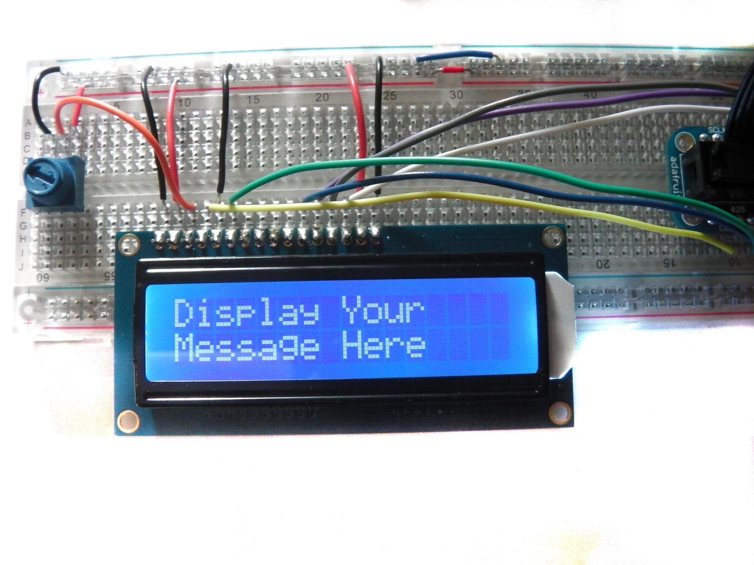
If everything is working correctly a message like the one below should appear on the screen:

Feel free to dive into the code of the program and change what's displayed on the LCD. To do so open the program to edit like before and scroll to the last line of the code:
lcd.message(“ Adafruit 16x2 Standard LCD”)
Simply change what is typed in the brackets after lcd.message() to display the text you want. The command is used to wrap the text onto a new line. A neater way of doing this is to change the last part of the program to look like the following:
if __name__ == '__main__': lcd = Adafruit_CharLCD() message = raw_input("Type your message here ") lcd.clear() lcd.message(message)
This way when you run the program you will be prompted by "type your message here" to enter a message via your keyboard, which will then be displayed on the LCD. This was done by defining a new variable 'message' that is equal to the command raw_input(), which allows the user to manually enter text. The part within the brackets of the raw_input() command is simply printed on the computer screen to prompt you what to write.

Step 5 - IP clock example
Getting the LCD display to display some text of your choosing is cool but not that useful. Running the program Adafruit_CharLCD_IPclock_example.py will display the date/time and the IP address of the Pi on the LCD. The program calls upon the methods from the previous program Adafruit_CharLCD.py. Feel free to open the program to look at the coding. To do so open the program in python or use the command sudo nano Adafruit_CharLCD_IPclock_example.py in the terminal.

Run the program (from the same directory as before) by typing the following in a terminal window:
sudo ./Adafruit_CharLCD_IPclock_example.py
If everything works correctly the display should look like this:

And that's it!