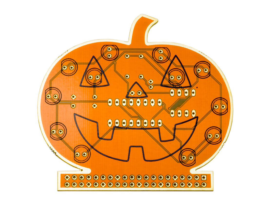
Halloween Pumpkin Solder Guide
Get soldering this Halloween with our super spooky Halloween Pumpkin and your Raspberry Pi!
Here are the parts from the kit:
Start by adding the 8.2k ohm resistor to designator R1
8.2k = Grey Red Red
Flip the board over, solder each leg and trim the excess leg.
Now for R2, we need a 10k ohm resistor here. Again, insert the legs, flip the board over, solder and trim.
10k = Brown Black Orange
R3 needs a 220 ohm resistor.
R4 needs a 47 ohm resistor.
Now we can move on to the capacitors. Lets start with designator C2 (don't worry, C1 isn't there!). C2 should be a 10nF capacitor. This is the small yellow component.
Then on to C3. This is an electrolytic capacitor. These have a polarity so you need to make sure you get it round the correct way. The PCB has a little + and - symbol by the holes and the capacitor has the negative leg marked
Time to solder the IC chip holders. Again, you need to make sure you get these the correct way round. There is a half circle cutout printed on the PCB which needs to line up with the half circle cut out in the holder.
The last component on this side of the PCB is the 90 degree header.
Time to flip the PCB over and start adding the LEDS
LEDs also have a polarity, so make sure these are inserted the correct way round. The outline of the LED printed on the PCB has a flat edge. This indicates the negative leg. The LEDs themselves also have a flat edge, and also have a shorted negative leg.
Insert one of the green LEDs into one of the eye positions on the PCB. Turn the PCB over, solder each leg and trim the excess.
Insert the second green LED into the other eye position, flip, solder trim.
The remaining red LEDs go round the outside edge of the pumpkin.
And that's it! Your pumpkin is fully assembled.
Simply plug it into the GPIO of your Pi (make sure the face of the pumpkin is facing away from the Pi) and watch the LEDs do their thing!


