
Christmas Tree Solder Guide
Here are the parts from the kit:


Lets start by adding the resistors to the PCB. We need a 15k on R1, 1k on R2 and a 220 on R3 and R4. The colour codes for the resistors are as follows:
15k = Brown Green Orange
1k = Brown Black Red
220 = Red Red Brown
As you add each resistor, flip the PCB over and bend the pins to stop the resistor from falling out. (We will solder them all in a bit)


Now we can add the capacitors. We need a 10nF ceramic on C2 and a 47uF electrolytic on C3. Whilst the ceramic doesn't have a polarity, the electrolytic does! Make sure you get this the right way round. There is a + and - on the PCB and the negative leg is indicated on the capacitor.


Now we can flip the PCB over and solder all the legs in place.


Once you have soldered a compontent in place, you can trim the legs down.


Next, we can add the 8 pin DIP socket. The DIP socket needs to be soldered in the correct orientation. The PCB has a white outline of the socket and one side has a half circle. Make sure the half circle on the socket lines up with the half circle on the PCB.


Flip the PCB over and solder into place.


Now we can add the 16 pin DIP socket. Just like the 8 pin DIP, this needs to be soldered in the correct orientation.


Flip the PCB over and solder into place.


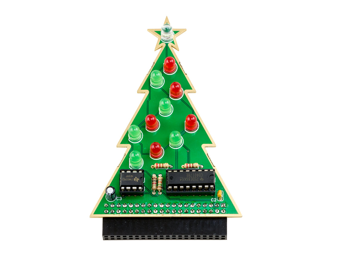
Time to add some LEDs! LEDs need to be added with the correct orientation. The short leg of the LED needs to go into the hole nearest the flat edge of the outline on the PCB.
Lets start with the clear white LED. This goes at the top of the tree.


Next you can add the red and green LEDs. These can go in any order that you wish! We've gone for the classic alternating pattern.


Flip the PCB over and solder into place.


The last compontent to solder is the 90 degree header. The header pins need to be inserted in from the back of the PCB and soldered on the front of the PCB. Double check with the image to make sure you get this correct.


With everything soldered into place, simply add the 8 pin IC (a 555 counter) and the 16 pin IC (a decade counter). Make sure these are inserted the correct way round. The half circle on the IC should match up with the half circle on the circle and PCB.


That's everything done! Now just plug it into your Raspberry Pi (make sure the LEDS are facing AWAY from the Pi), give your Pi some power and watch your Christmas Tree twinkle!
The white LED should flicker as the red and green LEDs "run" up the tree.


2 comments
The Pi Hut
@David – The pins will match the Raspberry Pi GPIO header – so wherever the 5V GPIO pin would be when sat on a Pi, that will be the 5V line, and the same for GND.
I’m not 100% sure if every GND pin on the board has a connection, but if you’re wiring manually, try the GND pins nearest the 5V pins to start with (most likely these are used), then work your way along until you find one that works.
DAVID MAY
JUST BUILT THE XMAS TREE AND THERE ARE NO INSTRUCTONS ON HOW TO CONNECT A 5VOLT SUPPLY TO USE IT WITHOUT THE RASPBERRY PI.
WHICH PINS ARE PLUS AND MINUS
THANK YOU
JUST BUILT THE XMAS TREE AND THERE ARE NO INSTRUCTONS ON HOW TO CONNECT A 5VOLT SUPPLY TO USE IT WITHOUT THE RASPBERRY PI.
WHICH PINS ARE PLUS AND MINUS
THANK YOU