RTD Data Acquisition 8-Layer Stackable HAT for Raspberry Pi [Discontinued]
Price:
Sale price
£68.50
Login / Signup
Cart
Your cart is empty


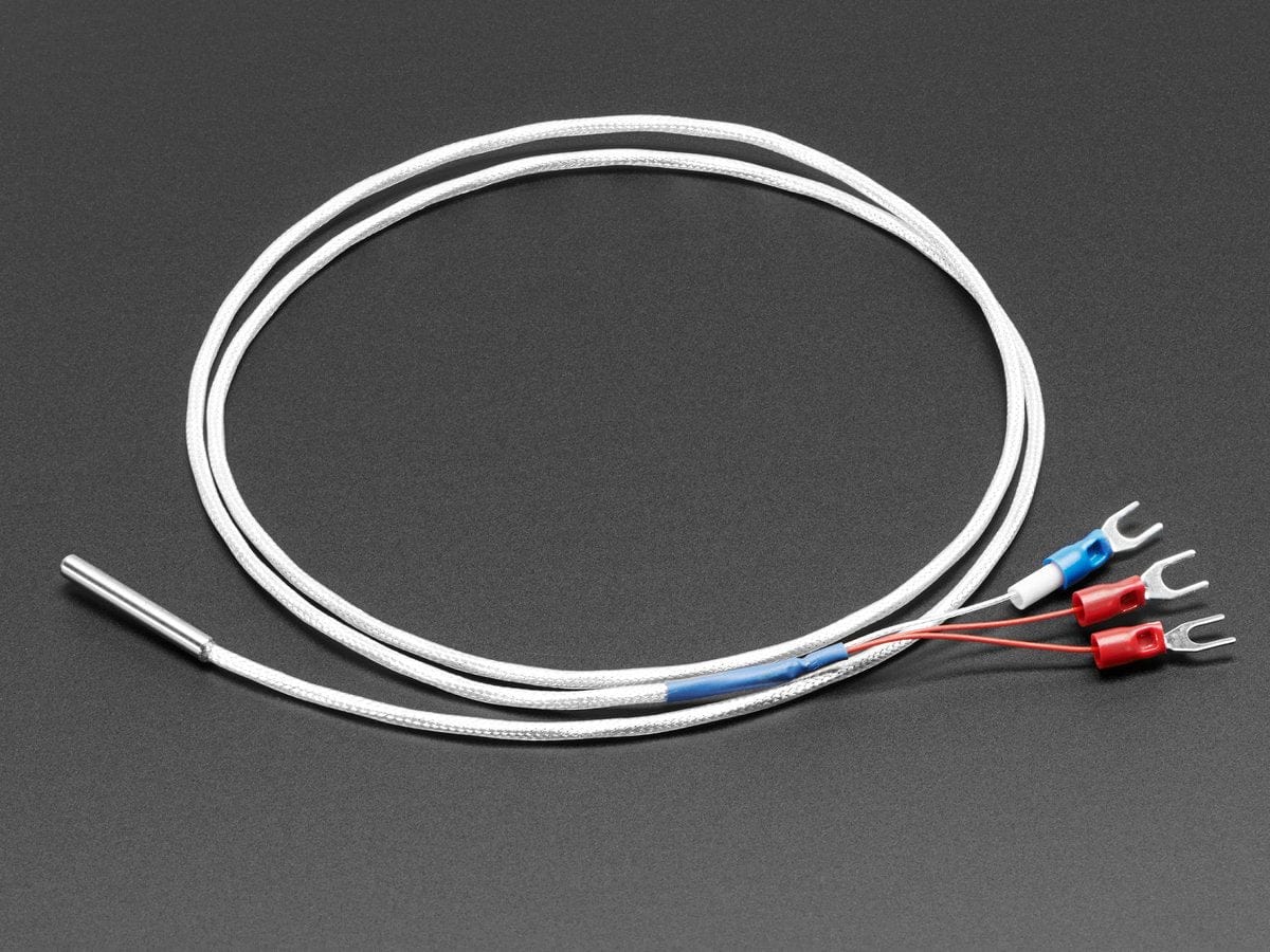
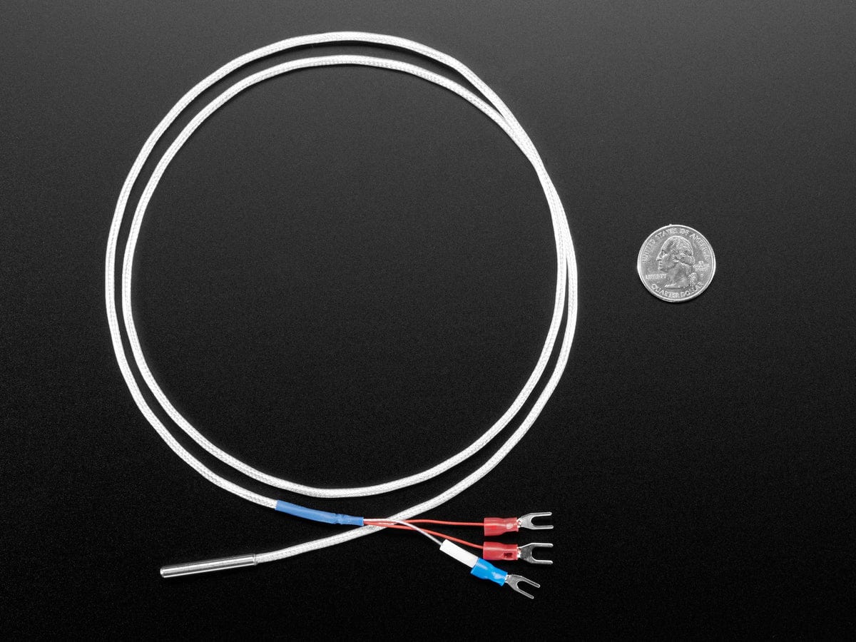
The RTD Data Acquisition Card offers a compact and inexpensive solution for reading and storing data from up to 64 RTD-100 temperature sensors with a Raspberry Pi.
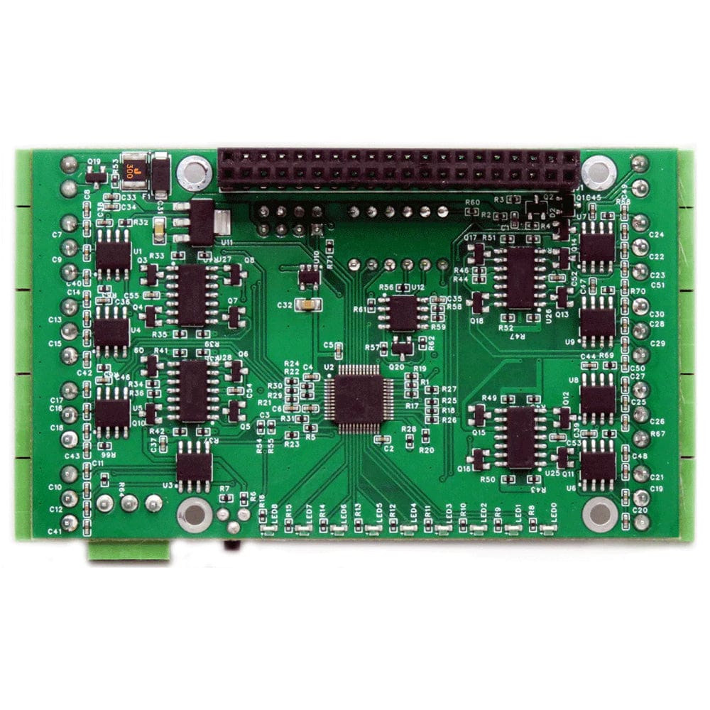
Using two ADS1248 24-bit delta-sigma converters with four channels each, the card achieves better than 0.1%. Field calibration with a precision 100Ω resistor can lead to 0.01% precision.
Since temperature measurement using RTD is based on resistance, the resistance in the lead wires and connectors must be taken into account when calculating the overall resistance in the system circuit. Using a 3-wire circuit design allows lead wire resistance to be factored out of the overall calculation.
Please note the board layout may change slightly between batches (such as the pin jumper headers). If your project or design is reliant on the positioning of pins and other parts, please contact us first and we'll be happy to send images of the current batch.
For any technical questions about this product please email support@sequentmicrosystems.com
Note: Raspberry Pi is NOT included
Compatability
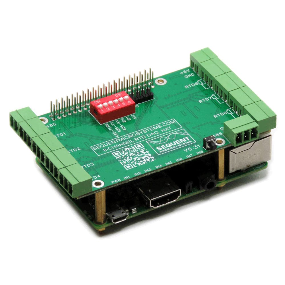
The card is compatible with all 40-pin Raspberry Pi versions from Zero to 4. It shares the I2C bus using only two of the Raspberry Pi’s GPIO pins to manage all eight cards.
This feature leaves the remaining 24 GPIOs available for the user.
Power Requirements
The RTD Data Acquisition card needs 5V to operate and can be powered from the Raspberry Pi. The cards require 50mA to operate.
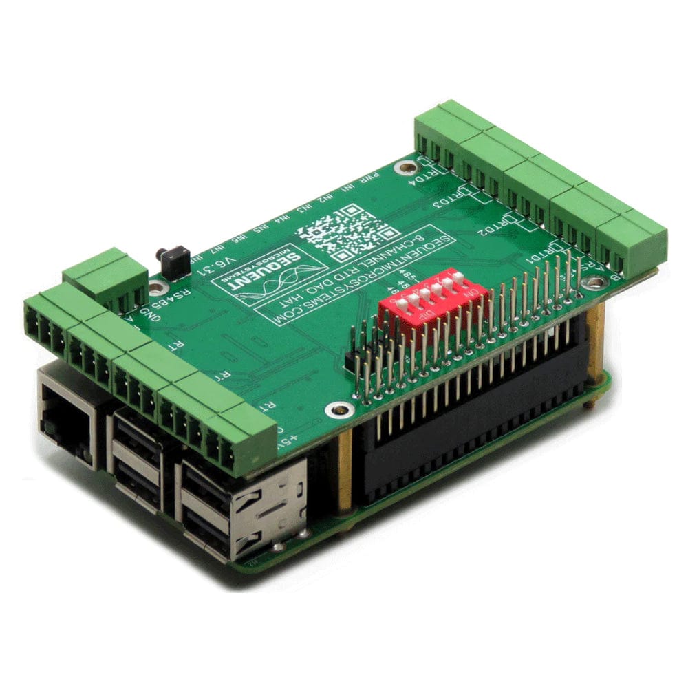
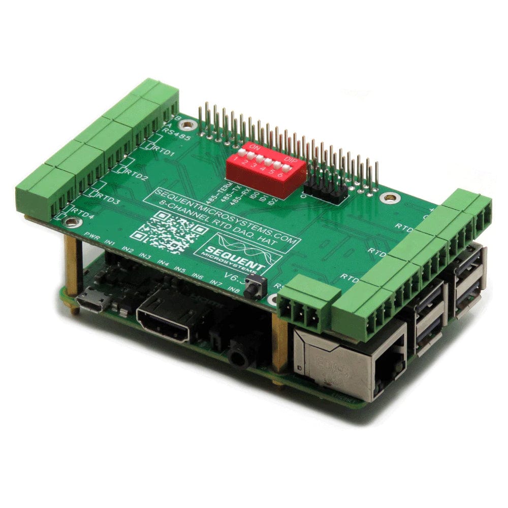
Stacking Multiple Cards
Up to eight RTD Data Acquisition cards can be stacked on your Raspberry Pi.
Each card is identified by jumpers you install to indicate the level in the stack. Cards can be installed in any order. For your convenience, two stack jumpers are provided with each card.
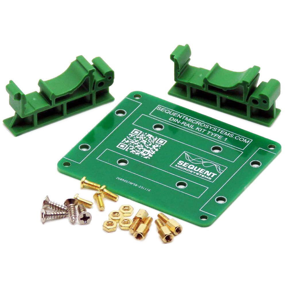
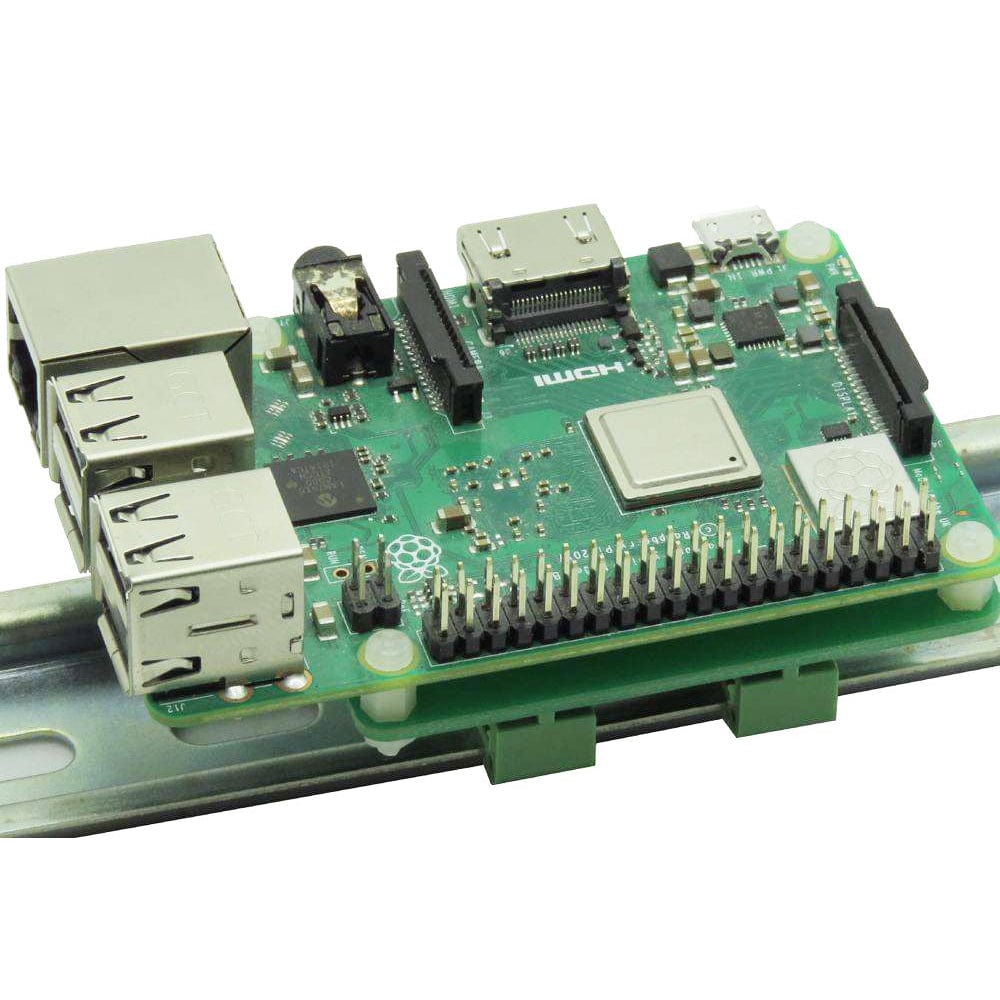
DIN-Rail Mounting
The RTD Data Acquisition card can be installed parallel on a DIN-Rail using the DIN-Rail Kit Type 1, or perpendicular using the DIN-Rail Kit Type 2.
Software Interfaces
You can write your own Data Acquisition system in C, C++, PERL or the language of your choice using the Command Line functions or the Python Library. A browser interface can easily be deployed using Node-Red.
Field Calibration
Field calibration to 0.01% precision can be achieved using an external high precision resistor. Software commands permit the user to calibrate the card in two points (the 2 points must be as far as possible but inside the measurement range).
The resulting values are stored in flash and used for resistance measurements compensation witch will reflect in the temperature readings.
The resistance to temperature conversion is made by the simplest equation T = (R - R0)/(R0*k), where T is temperature in Celsius degree; R is the sensor resistance; R0 is the resistance at 0 deg Celsius (100 for PT100) and k= 0.00385. If the user needs to use the polynomial equation, the resistance measurements are available.
RS485/MODBUS Communication
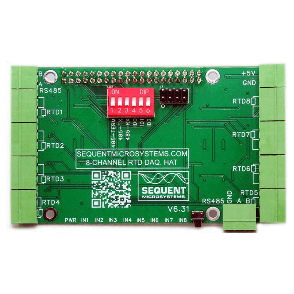
The card contains a standard RS485 transceiver which can be accessed by the local processor or by Raspberry Pi. The desired configuration is set from two bypass jumpers on configuration connector J3.
See in the card layout section below jumpers "485-RX" and "485-TX". If jumpers are installed, Raspberry Pi can communicate with any device with an RS485 interface. In this configuration, the card is a passive bridge that implements only the hardware levels required by the RS485 protocol. To use this configuration, you need to tell the local processor to release control of the RS485 bus:
~$ rtd [0] rs485wr 0 0 0 0 0
If jumpers are removed, the card operates as MODBUS slave and implements the MODBUS RTU protocol. Any MODBUS master can access all the card's inputs, and set all the outputs using standard MODBUS commands. A detailed list of commands implemented and parameters addresses can be found on GitHub.
In both configurations, the local processor needs to be programmed to release (jumpers installed) or control (jumpers removed) the RS485 signals. See the command line online help for further information.
LED Threshold Signals
The RTD board has eight LEDs that can be activated when the input reaches a preset threshold. The threshold can be set in software for each input.
Firmware Update
The card firmware can be updated in the field by running a command. The update is made with the latest firmware version located on our servers. More instructions about the process can be found on GitHub.
Please make sure there is no process, like Node-Red or python scripts, that tries to access the card during the update process.
Note: the PT100/1000 2-pin jumpers have been removed due to the disappearance of the ADS1248 A/D converter from the marketplace. Board layout/connectors vary slightly by batch

Your payment information is processed securely. We do not store credit card details nor have access to your credit card information.