Login / Signup
Cart
Your cart is empty
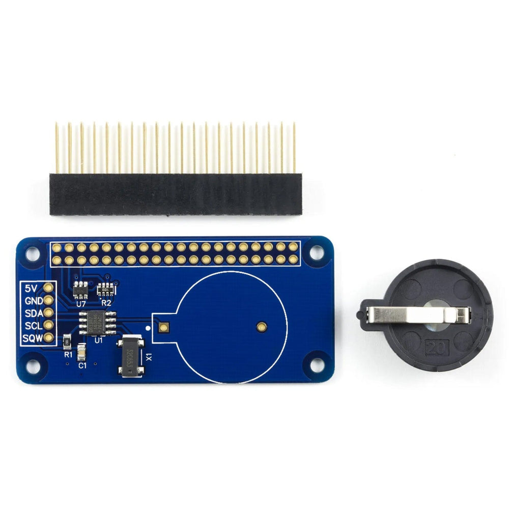
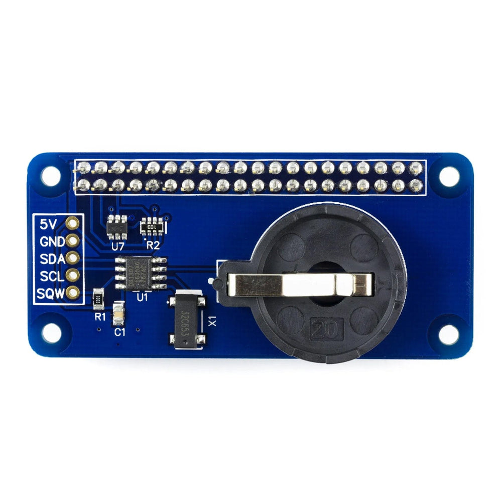
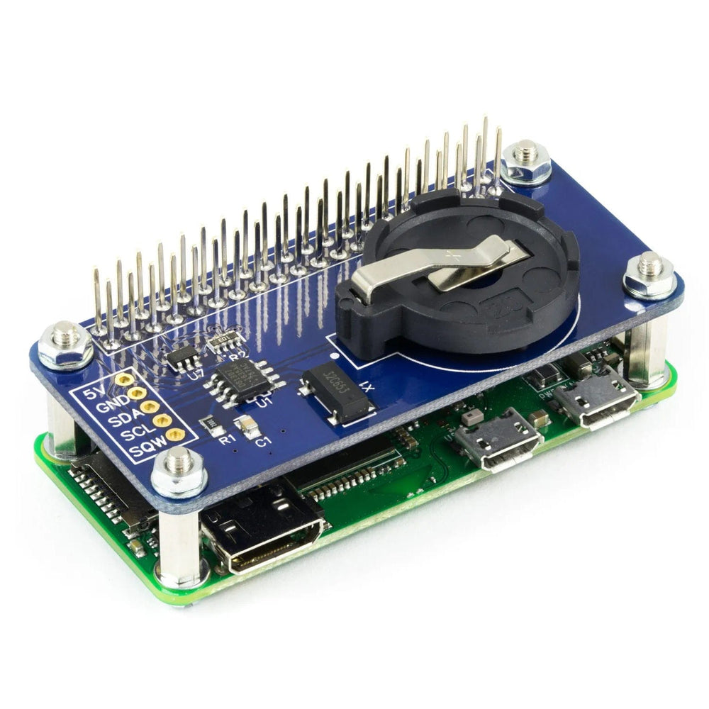
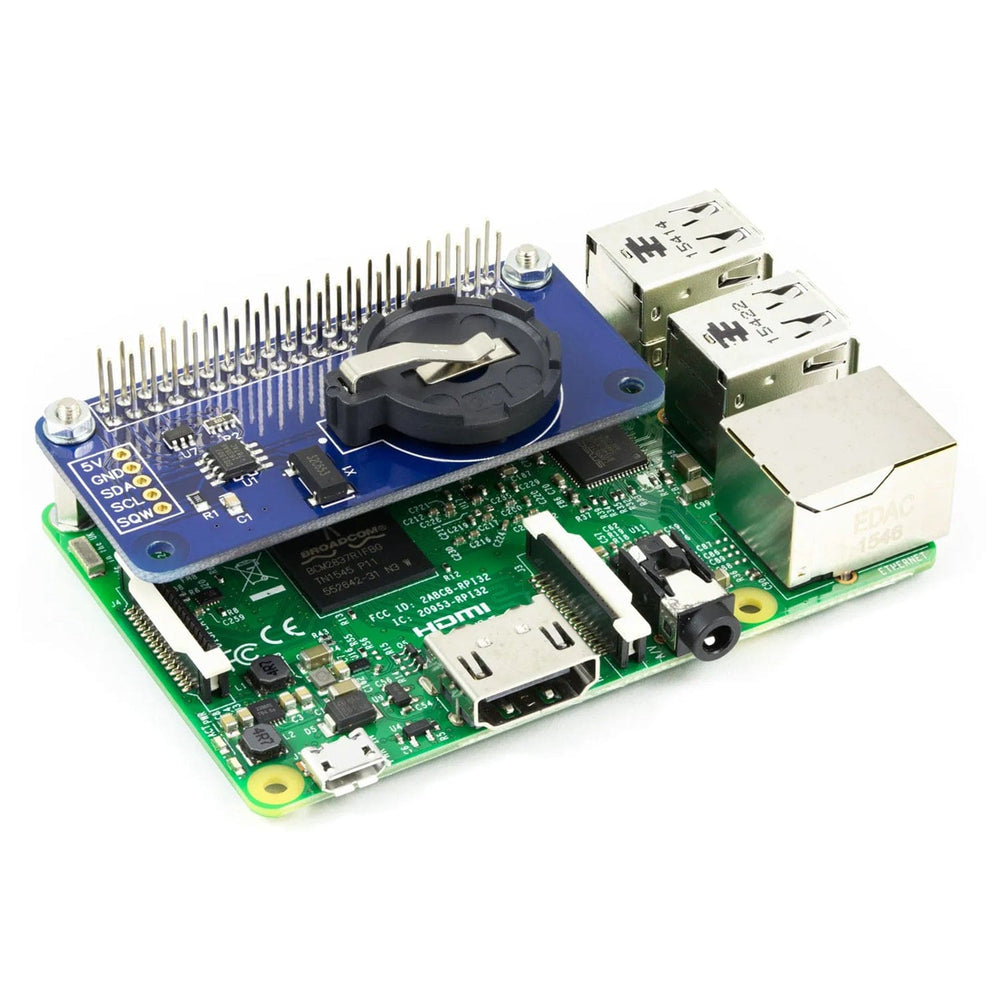
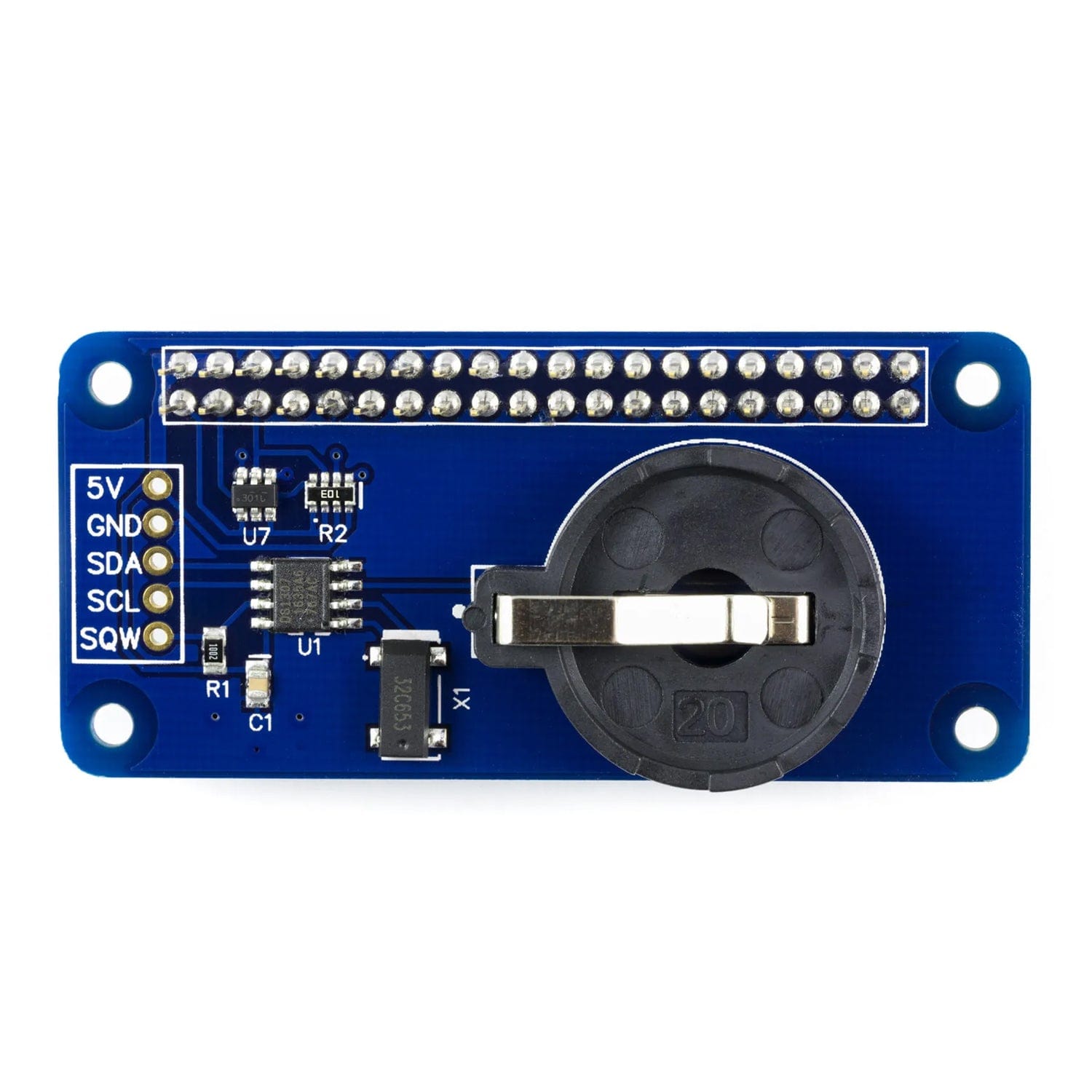
The Raspberry Pi is a great low cost computer with thousands of different uses but one thing it does not come with is a real-time clock. This means that every time you switch off your Raspberry Pi it forgets what the time is and you have to manually set it again next time you switch your Raspberry Pi on.
Soldering required! This product comes unassembled and unsoldered.
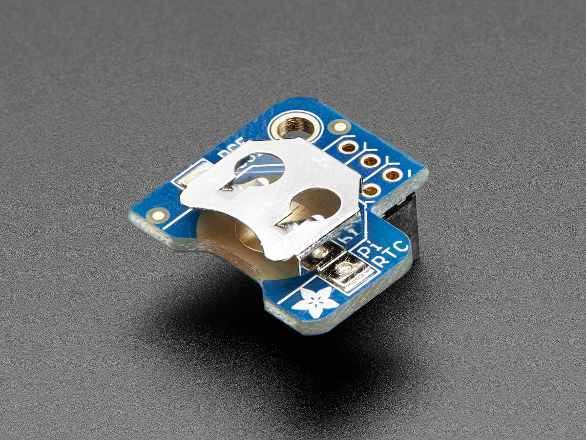
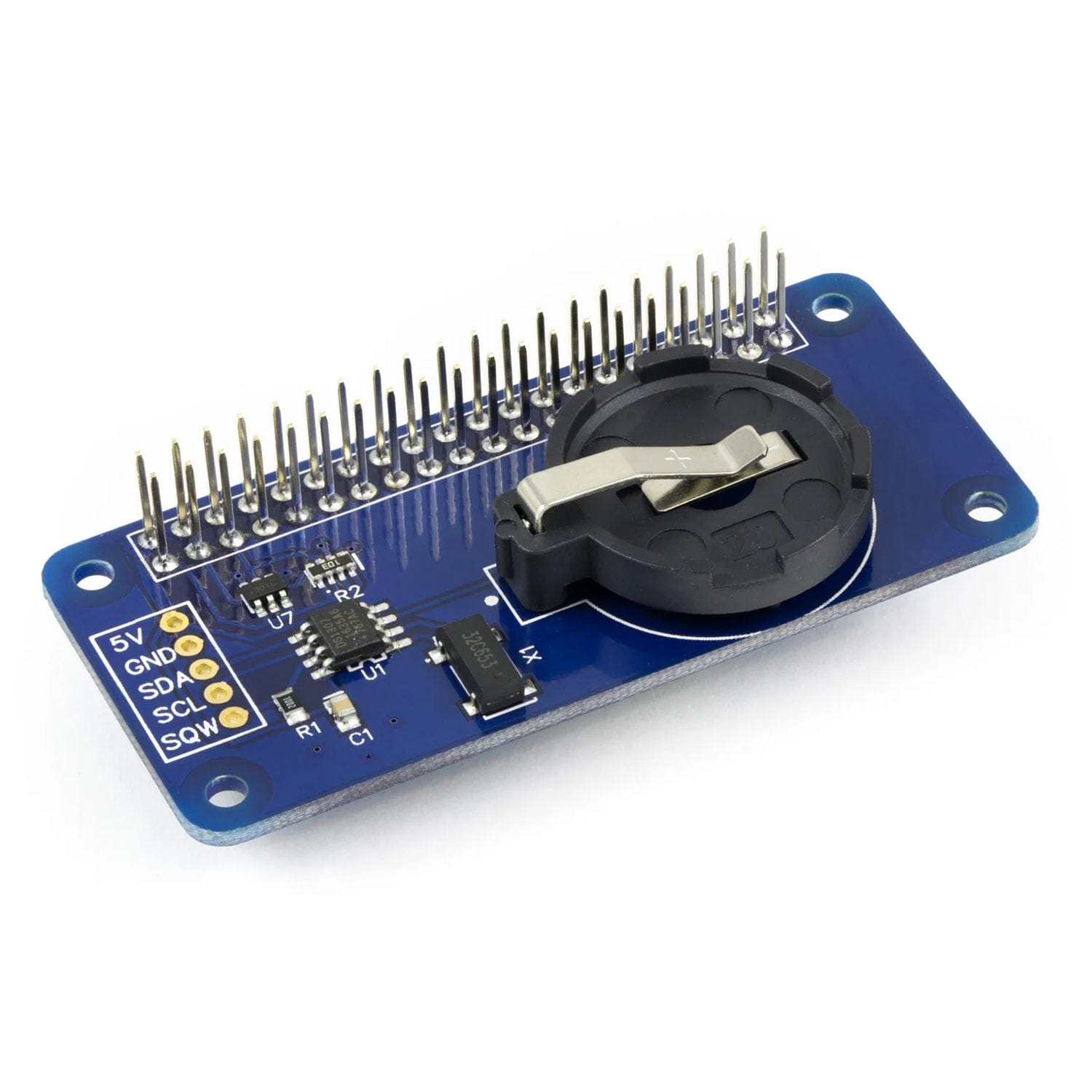
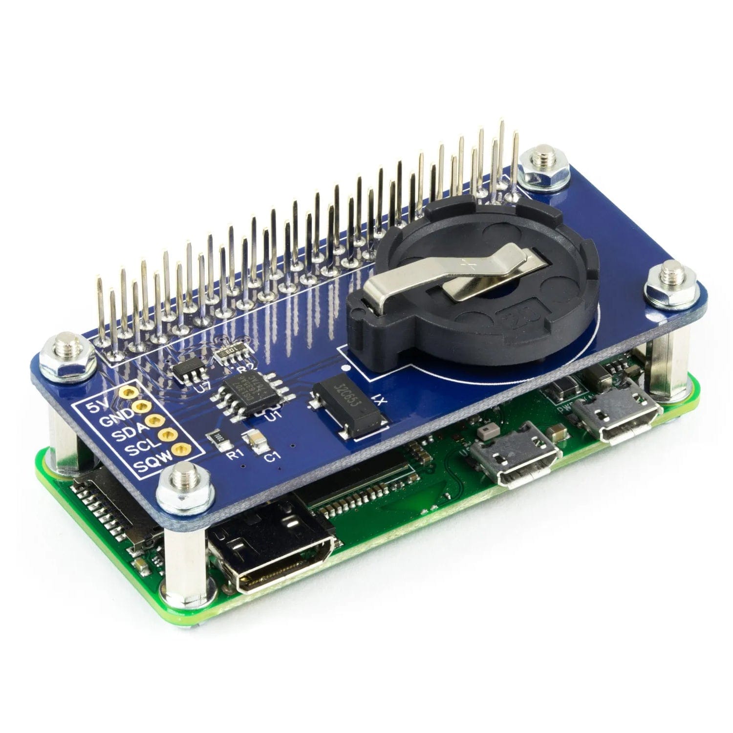
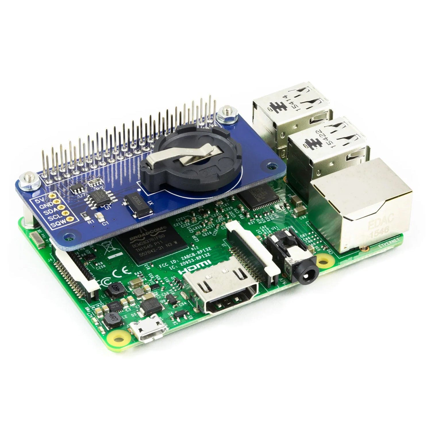
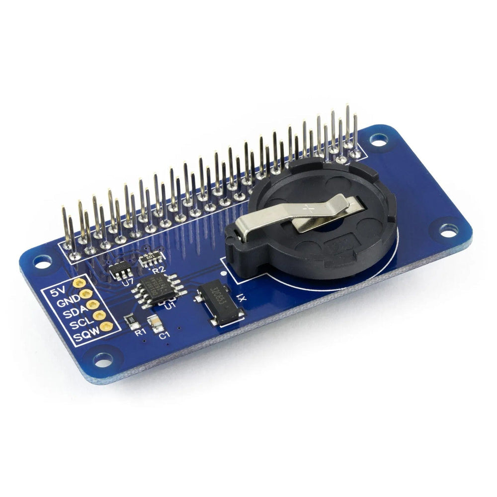
The RTC Pi Zero is a battery backed real-time clock module for the Raspberry Pi Zero. It keeps track of the time while the Raspberry Pi is switched off and allows the Raspberry Pi to retrieve the current date and time from the RTC Pi Plus when it is switched back on.
The RTC Pi Zero is powered through the host Raspberry Pi using the GPIO port and extended pins on the GPIO connector allow you to stack the RTC Pi Zero along with other expansion boards. The RTC Pi Zero uses the DS1307 RTC real time clock and a CR2032 battery to maintain the date and time when the main system power is not available.
Unlike most other DS1307 based RTC modules the RTC Pi also includes an I2C logic level converter allowing you to connect other 5V I2C devices to your Raspberry Pi.
The RTC Pi Zero is very useful for standalone projects where your Raspberry Pi will not have a network connection and therefore no way to retrieve the current date and time from the internet.
Mounting holes are provided so you can securely bolt the RTC Pi Zero to your Raspberry Pi with our mounting kit (sold separately).
The RTC Pi Zero can also be used on Arduino boards when connected via the I2C bus.
The i2c address for the DS1307 RTC is 0x68. If you use this board along side the ADC Pi or ADC Differential Pi boards you will need to change the i2C address on those boards.
Warning: Do not connect the RTC Pi Zero to your Raspberry Pi when the power is connected without a CR2032 battery installed. This can cause damage to the DS1307 RTC chip.
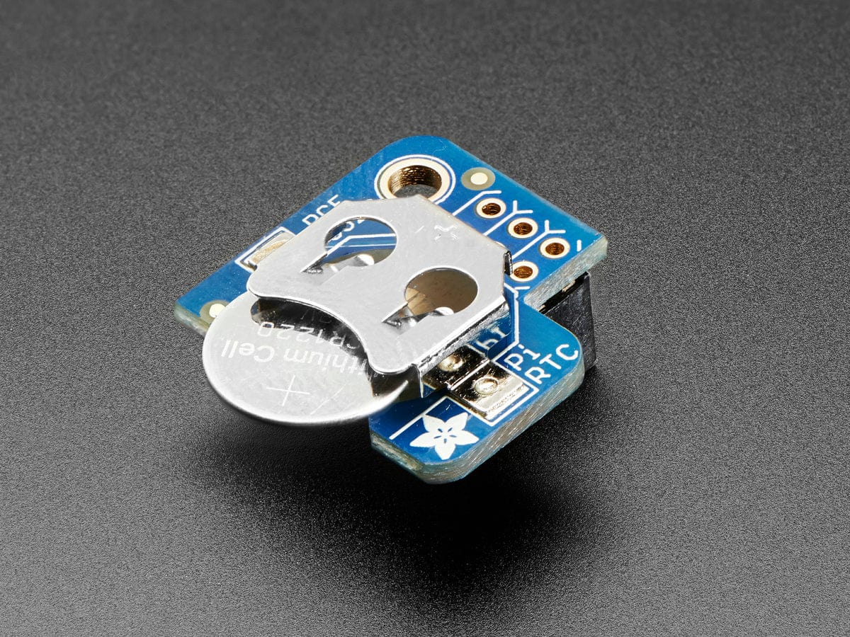
The RTC Pi Plus uses a CR2032 button battery (battery not included).
| Raspberry Pi Model A | No |
| Raspberry Pi Model B | No |
| Raspberry Pi 1 Model A+ | Yes |
| Raspberry Pi 1 Model B+ | Yes |
| Raspberry Pi 2 Model B | Yes |
| Raspberry Pi 3 Model B | Yes |
| Raspberry Pi Zero | Yes |
| ODroid C1 | Yes |
| ODroid C2 | Yes |
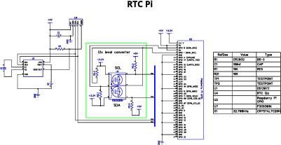
Click to download schematic PDF.
Click image to enlarge
We have python 2 and 3 libraries available for this expansion board. You can download all of the libraries from github at:
https://github.com/abelectronicsuk/
To download the Python 2 libraries to your Raspberry Pi type in terminal:
git clone https://github.com/abelectronicsuk/ABElectronics_Python_Libraries.git
To download the Python 3 libraries to your Raspberry Pi type in terminal:
git clone https://github.com/abelectronicsuk/ABElectronics_Python3_Libraries.git
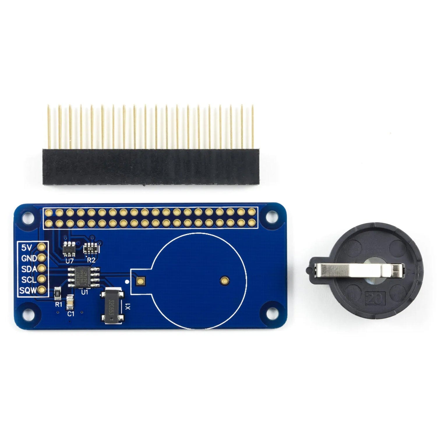
The RTC Pi Zero is supplied with the 40 pin GPIO connector and the battery holder unsoldered.
We supply the RTC Pi Zero this way because the Raspberry Pi Zero is also supplied without a GPIO header and the RTC Pi Zero could therefore be fitted both above or below the Raspberry Pi Zero.
Before using the RTC Pi Zero you will need to solder the 40 pin GPIO connectors onto the PCB and the battery holder.
We suggest soldering the 40 pin GPIO connector first and then the battery holder. Soldering the battery holder first will make it difficult to access the pins on the GPIO connector. The PCB has an outline for the battery connector to ensure the correct fitting.
Download and print our PCB Header Assembly Jig to hold your circuit board when soldering the header pins.


