RS485 Pi
Price:
Sale price
£14.40
Stock:
Quantity:
Login / Signup
Cart
Your cart is empty


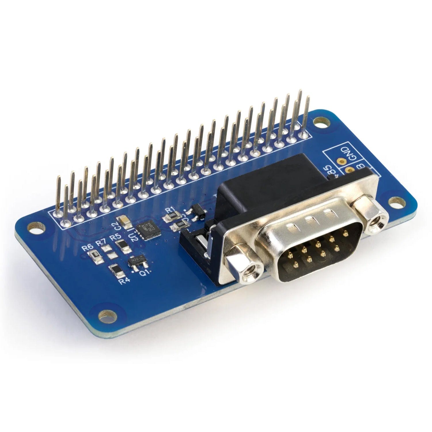
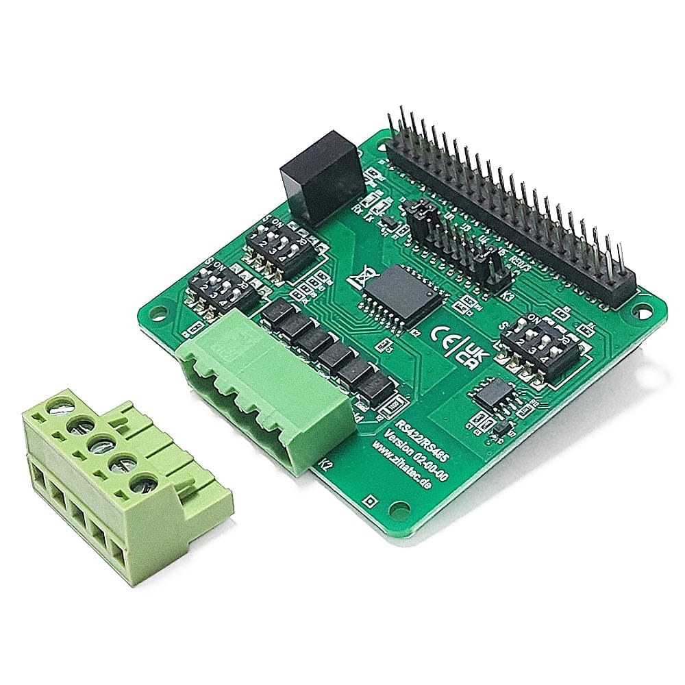
The RS485 Pi is a communication development board supporting the RS-485 serial protocol, designed to work with the Raspberry Pi and other compatible single-board computers.
Soldering required! This product comes unassembled and unsoldered.
The RS-485 port is connected to the UART port on the Raspberry Pi using a SN65HVD72 interface. The SN65HVD72 IC converts the 3.3V UART signals to RS-485 voltages allowing communication with RS-485 compatible devices over a DB9 serial cable or twisted pair cable. The RS-485 port can be accessed through the DB9 port or the solder points on the PCB.
The RS485 Pi contains protection against voltage spikes in the form of a TVS Diode and two 10-?, Pulse-Proof Thick-Film Resistors.
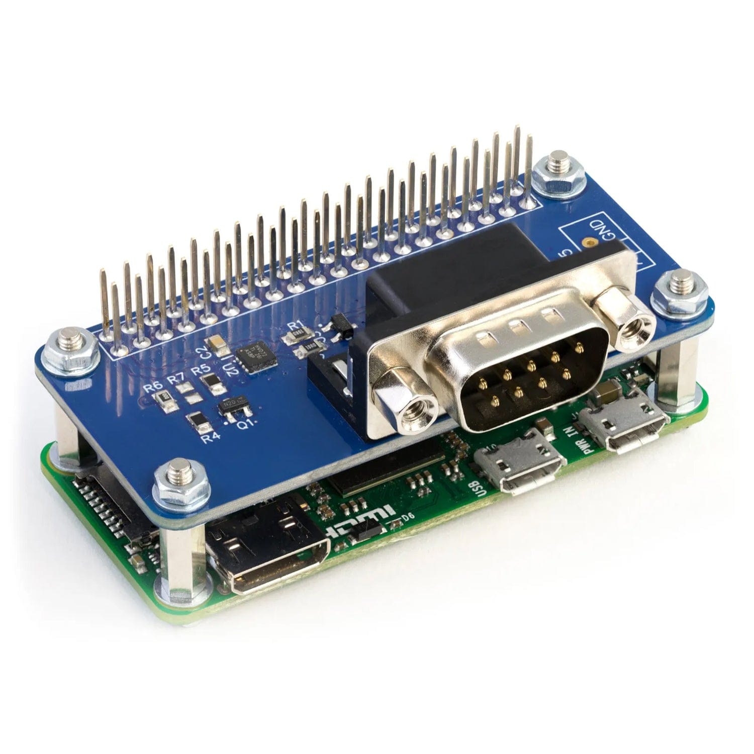
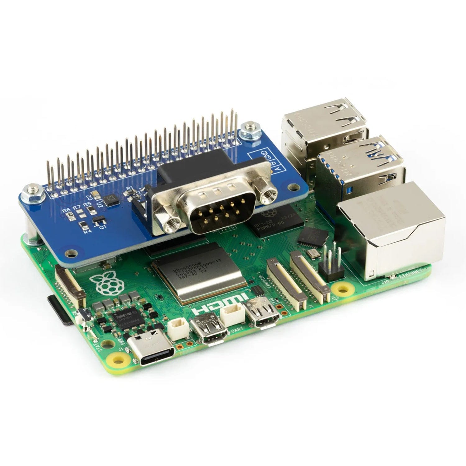
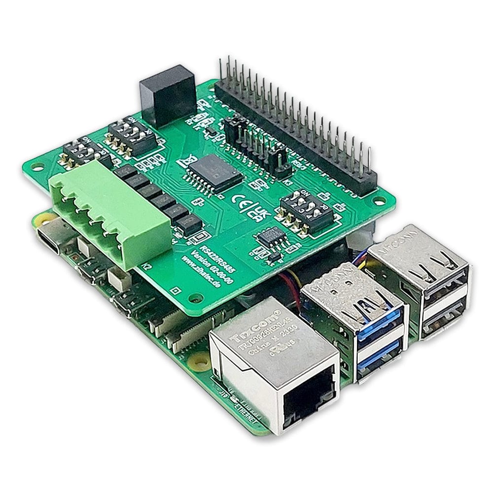
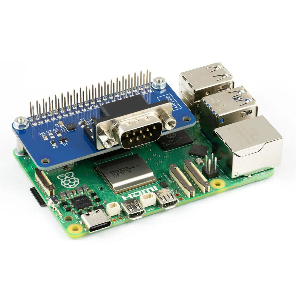
Please note that you can only use one RS485 Pi board on a Raspberry Pi. if stacking with other boards we recommend putting the RS485 Pi at the top of the stack due to the height of the DB9 connector.
| Supply Voltage | 3.3V |
| Logic Voltage at GPIO Port | 3.3V |
| Differential Input Voltage at A & B | -12V to +12V |
| High-level input voltage | 2V |
| Low-level input voltage | 0.4V |
| Signalling Data Rate | 250 kbps |
| Raspberry Pi Model A / B (Rev 1 original) | No |
| Raspberry Pi 1 Model A+ | Yes |
| Raspberry Pi 1 Model B+ | Yes |
| Raspberry Pi 2 Model B | Yes |
| Raspberry Pi 3 Model B * | Yes |
| Raspberry Pi 4 Model B | Yes |
| Raspberry Pi Zero / W / 2W | Yes |
*You need to use the latest Raspbian Jessie release and disable the built in Bluetooth to use the RS485 Pi on the Raspberry Pi 3, see ourKB page for the config changes needed.
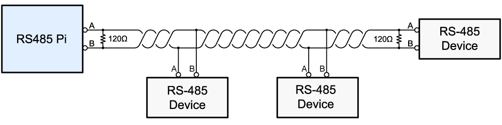
RS-485, also known as ANSI/TIA/EIA-485, TIA/EIA-485 or EIA-485 is a standard used in serial communication systems. Equipment using the RS-485 standard can be used over long distances in noisy environments. Unlike RS232, the RS-485 standard allows for multiple devices to be connected on the same network. The recommended arrangement for connecting devices to an RS-485 network is to use a series on nodes connected along a line or bus with terminating resistors used at either end of the bus to reduce reflections.
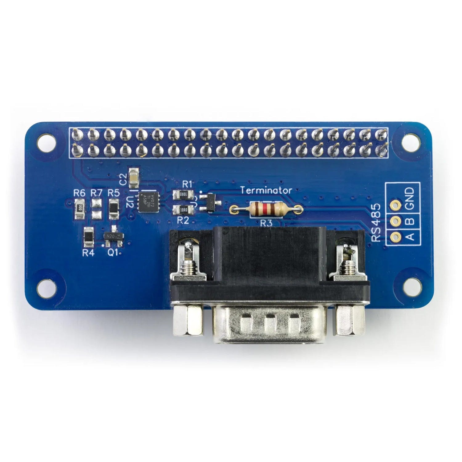
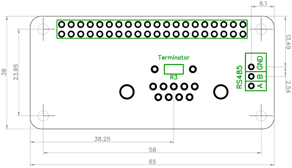
A 120-? resistor is included with the RS485 Pi which will need to be fitted if the board is connected to the end of the RS-485 bus. The diagram below shows a typical network of RS-485 devices.
The RS-485 port on the RS485 Pi can be accessed through the male DB9 socket or the solder points on the PCB. The DB9 socket uses three wires as shown on the diagram below.
|
DB9 connector as viewed from the front of the RS485 Pi |
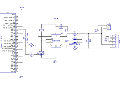
Click to download schematic PDF.
Click image to enlarge
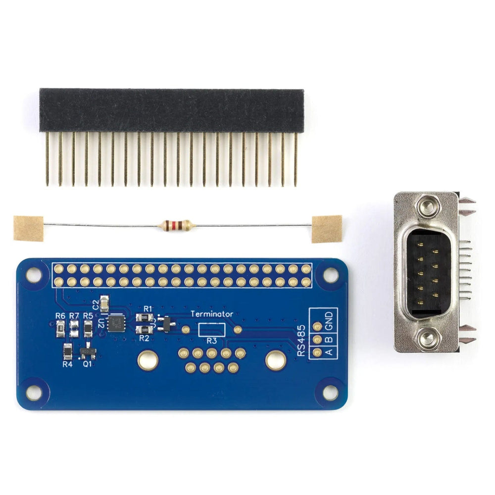
The RS485 Pi is supplied with the 40 pin GPIO connector and the DB9 connector unsoldered.
A 120R terminator resistor is included in the kit. This will be required if the RS485 Pi is used as an end node within an RS485 network.
Before using the RS485 Pi you will need to solder both connectors onto the PCB. We suggest soldering the 40 pin GPIO connector first and then the DB9 connector.
To make assembly easier we have designed a PCB header assembly jig which you can download and print.
Download and print our PCB Header Assembly Jig to hold your circuit board when soldering the header pins.
![]()
Your payment information is processed securely. We do not store credit card details nor have access to your credit card information.