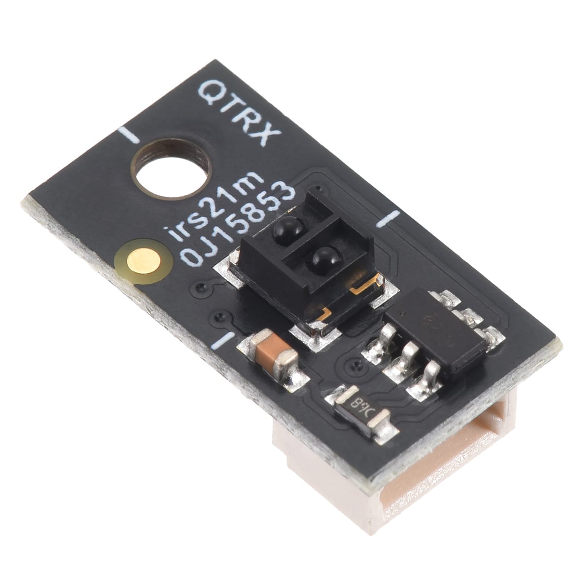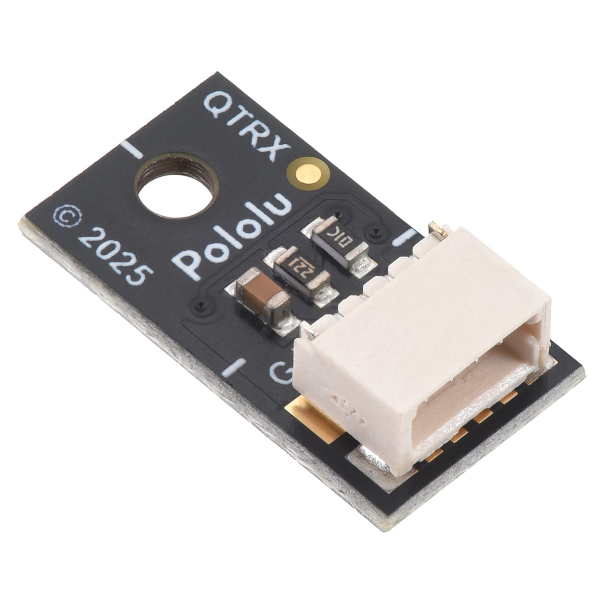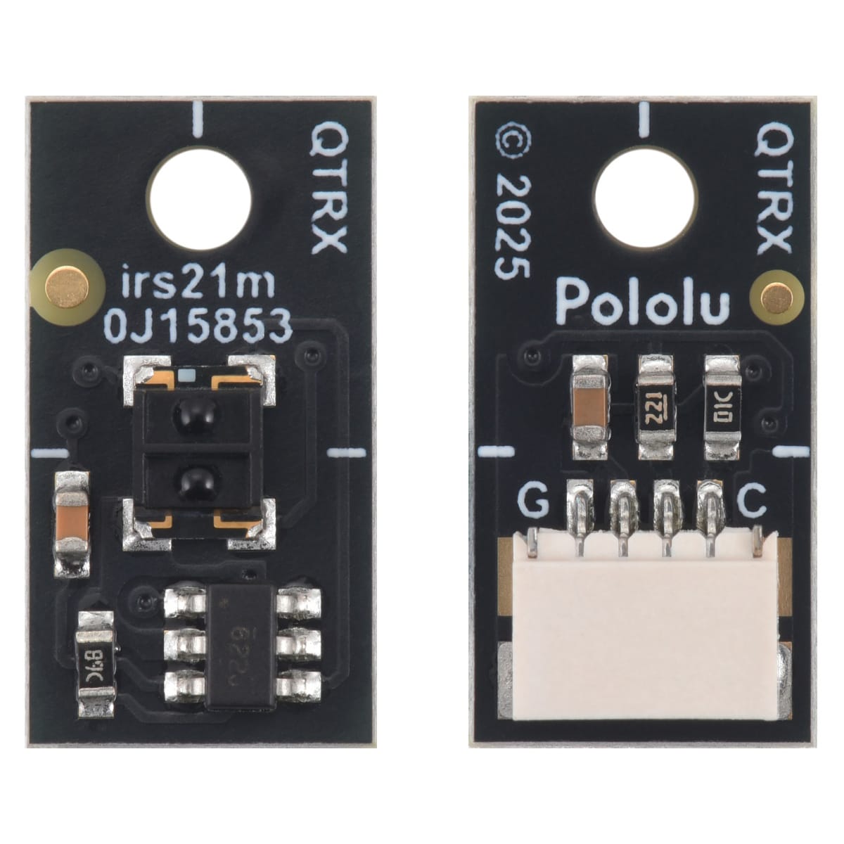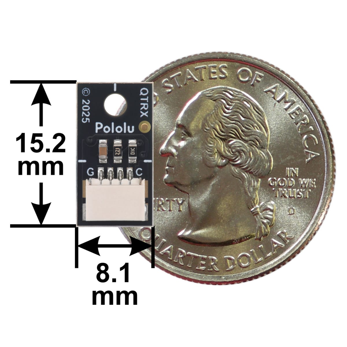
Pololu QTRX-MD-01RC-S Reflectance Sensor (RC Output)
Price:
Sale price
£4.20
Stock:
Quantity:
Login / Signup
Cart
Your cart is empty


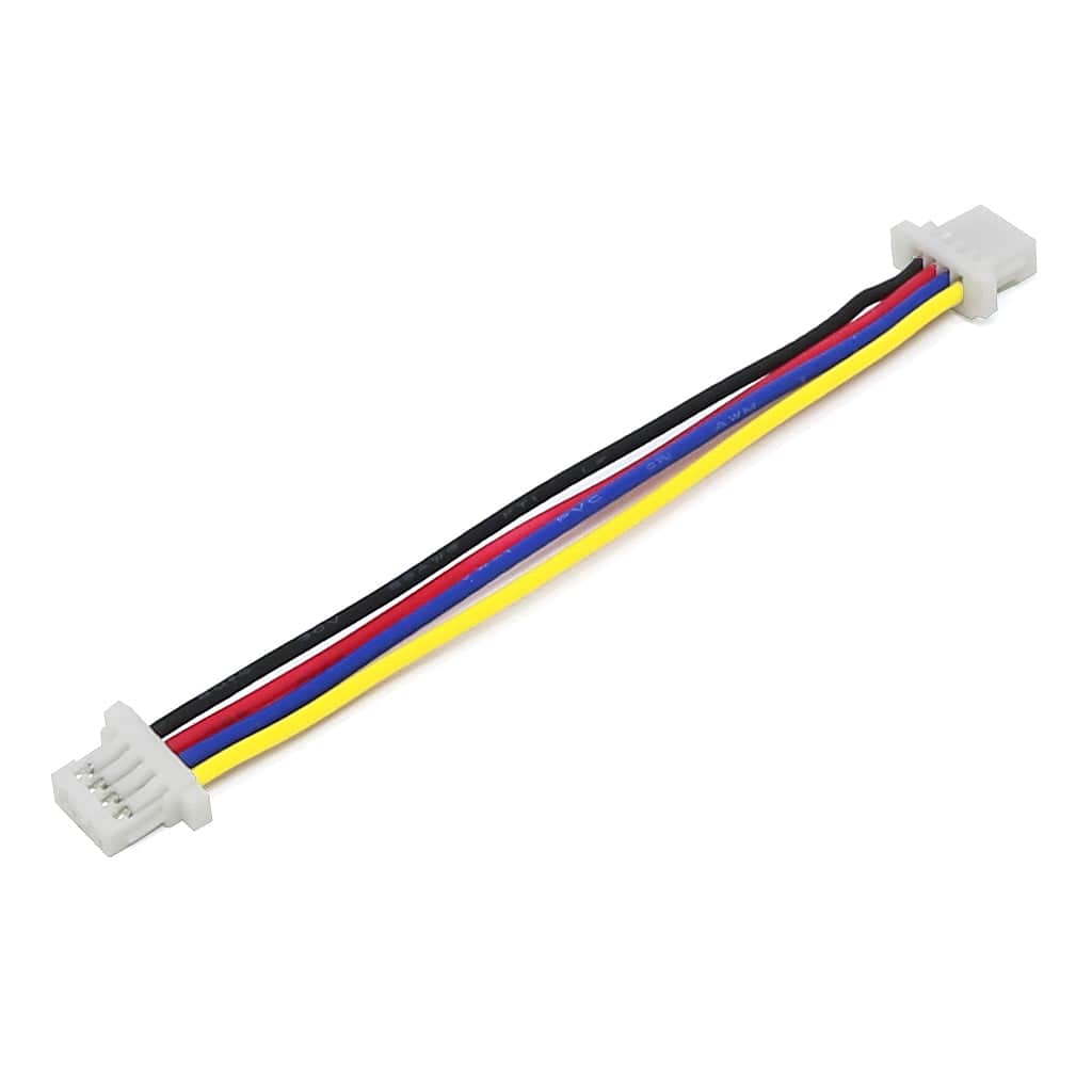


This Pololu sensor uses an IR LED and a phototransistor to measure the light reflected from nearby surfaces. It operates from 2.9–5.5V, with dimmable brightness control independent of the supply voltage. This change in reflectivity can be due to a colour change at a fixed distance, such as when sensing a black line on a white background, as well as due to a change in the distance to or presence of an object in front of the sensor.
The optimal range is <5 mm, but it can detect high-reflectance objects out to around 30mm. This version features a high-performance, low-current QTRX sensor with lenses and a connector that works with 4-pin JST SH-style cables (compatible with Qwiic, but the interface is not I²C), and has an RC (digital) output.
Our Arduino library makes it easy to use these sensor modules with an Arduino or compatible controller by providing methods for controlling the emitters, calibrating the module, and reading the individual sensor values. It also has a method specifically for line-following applications to compute the location of the line under the array.
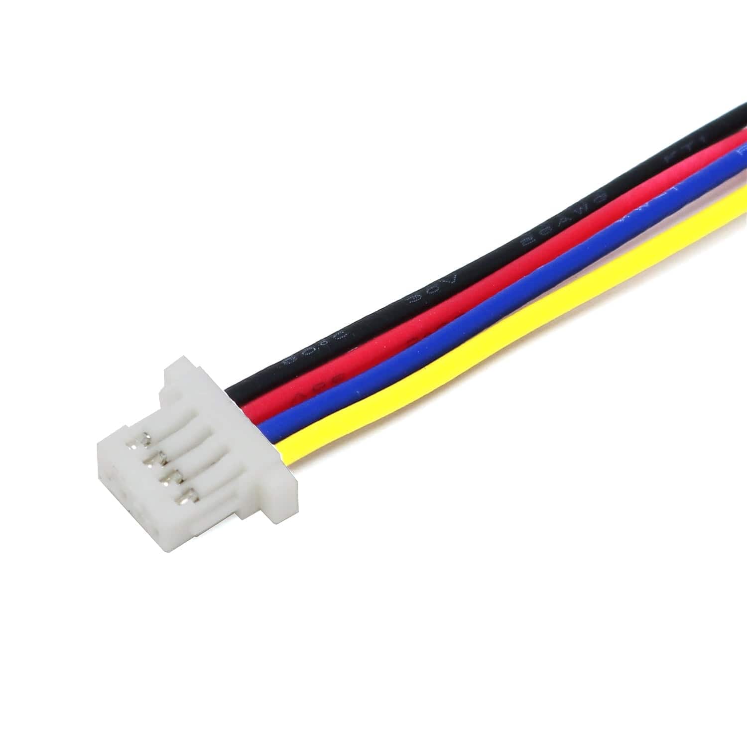
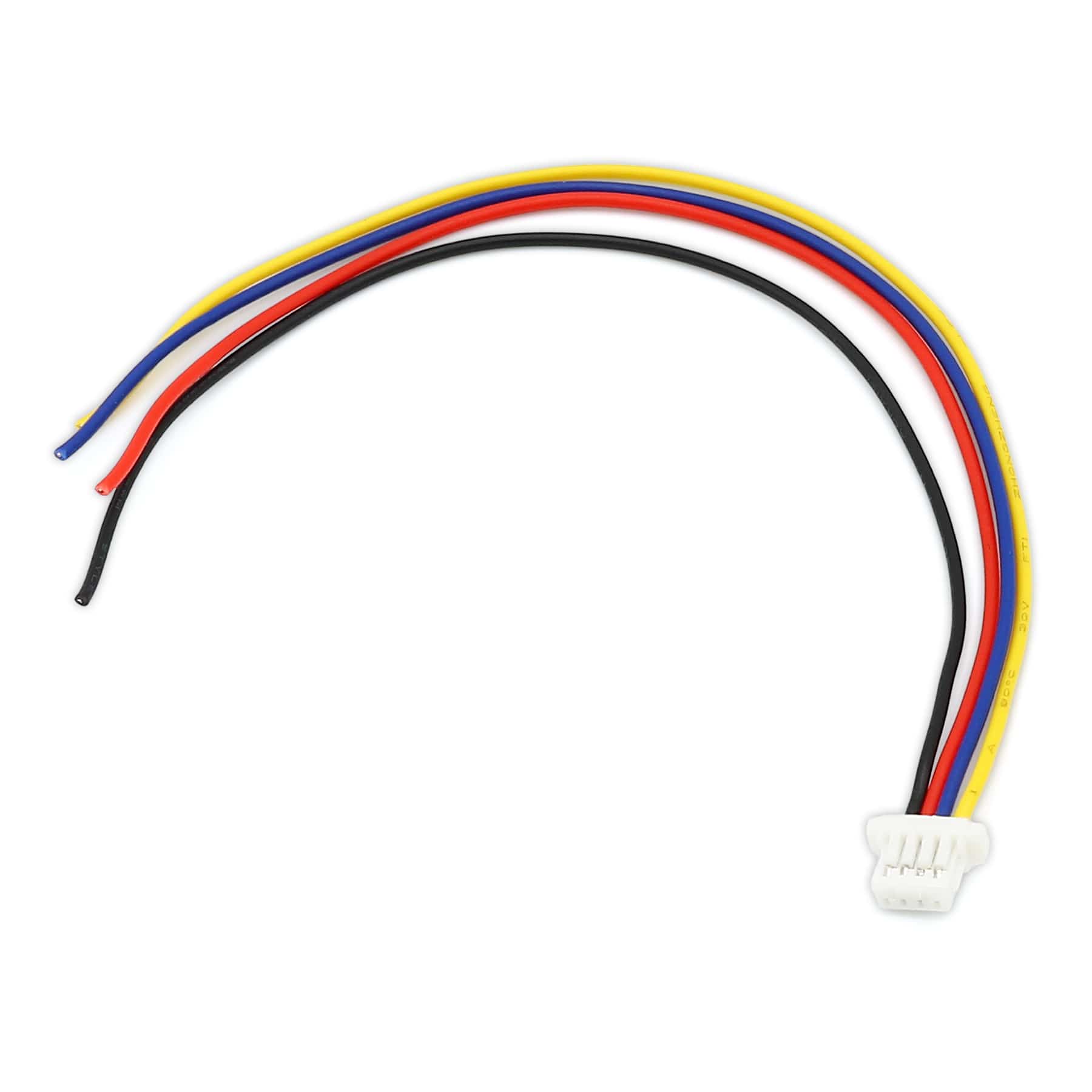
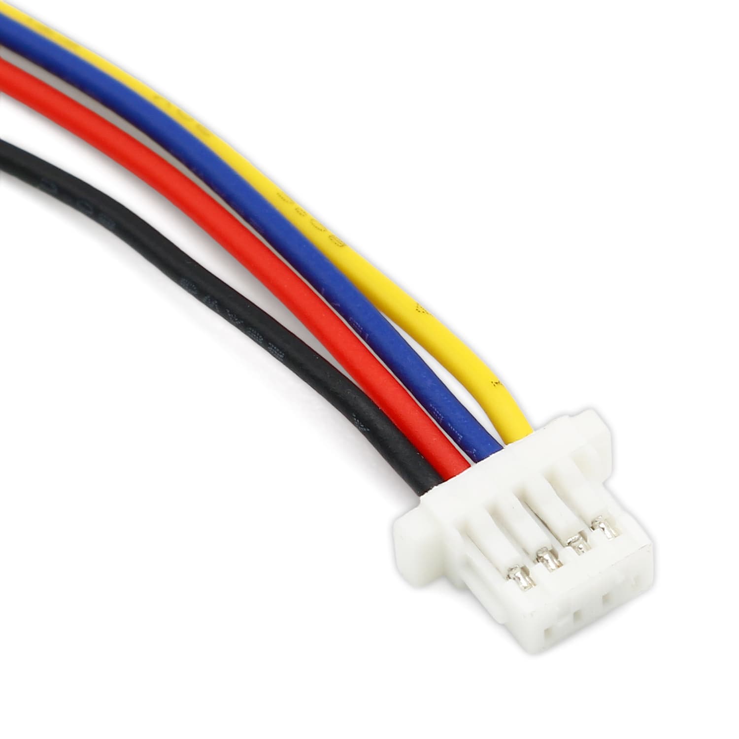
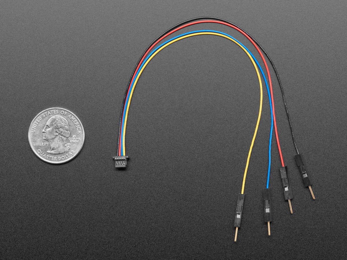
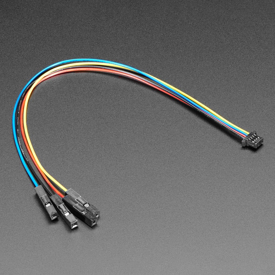
This sensor features JST SH-style, 4-pin, side-entry connector that works with 4-pin JST SH-style 'Qwiic' cables (cable not included), but please note that the interface is not I²C.

Each sensor on the RC versions requires a digital I/O line capable of driving the output line high and then measuring the time for the output voltage to decay. The typical sequence for reading a sensor is:
These steps can typically be executed in parallel on multiple I/O lines.
With a strong reflectance, the decay time can be as low as a few microseconds; with no reflectance, the decay time can be up to a few milliseconds. The exact time of the decay depends on your microcontroller’s I/O line characteristics. Meaningful results can be available within 1 ms in typical cases (i.e. when not trying to measure subtle differences in low-reflectance scenarios), allowing up to 1 kHz sampling of all sensors.
If lower-frequency sampling is sufficient, you can achieve substantial power savings by turning off the LEDs. For example, if a 100 Hz sampling rate is acceptable, the LEDs can be off 90% of the time, lowering average current consumption from 125 mA to 13 mA.
These reflectance sensor arrays maintain a constant current through their IR emitters, keeping the emitters’ brightness constant, independent of the supply voltage (2.9 V to 5.5 V). The emitters can be controlled with the board’s CTRL pins, and the details of the control depends on the array size and density.
MD units with 2 or fewer sensors have a single CTRL pin that controls all of the emitters.
Driving a CTRL pin low for at least 1 ms turns off the associated emitter LEDs, while driving it high (or allowing the board to pull it high) turns on the emitters with the board’s default (full) LED current, which is 3.5 mA for “QTRX” versions. (The emitter LEDs are generally driven in pairs, with the two emitters in each pair connected in series, so the total board current is not the LED current times the number of LEDs as you might otherwise expect; it is usually closer to half that.)
For more advanced use, the CTRL pin can be pulsed low to cycle the associated emitters through 32 dimming levels. To send a pulse, drive the CTRL pin low for at least 0.5 μs (but no more than 300 μs), then high for at least 0.5 μs; (it should remain high after the last pulse). Each pulse causes the driver to advance to the next dimming level, wrapping around to 100% after the lowest-current level.
Each dimming level corresponds to a 3.33% reduction in current, except for the last three levels, which represent a 1.67% reduction, as shown in the table below. Note that turning the LEDs off with a >1 ms pulse and then back on resets them to full current.
| Dimming level (pulses) | Emitter current (%) | Dimming level (pulses) | Emitter current (%) |
|---|---|---|---|
| 0 | 100.00% | 16 | 46.67% |
| 1 | 96.67% | 17 | 43.33% |
| 2 | 93.33% | 18 | 40.00% |
| 3 | 90.00% | 19 | 36.67% |
| 4 | 86.67% | 20 | 33.33% |
| 5 | 83.33% | 21 | 30.00% |
| 6 | 80.00% | 22 | 26.67% |
| 7 | 76.67% | 23 | 23.33% |
| 8 | 73.33% | 24 | 20.00% |
| 9 | 70.00% | 25 | 16.67% |
| 10 | 66.67% | 26 | 13.33% |
| 11 | 63.33% | 27 | 10.00% |
| 12 | 60.00% | 28 | 6.67% |
| 13 | 56.67% | 29 | 5.00% |
| 14 | 53.33% | 30 | 3.33% |
| 15 | 50.00% | 31 | 1.67% |
For example, to reduce the emitter current to 50%, apply 15 low pulses to the CTRL pin and then keep it high after the last pulse.
Cables/headers not included
Your payment information is processed securely. We do not store credit card details nor have access to your credit card information.