
Challenger M0 WiFi
Price:
Sale price
£20.50
Stock:
Quantity:
Login / Signup
Cart
Your cart is empty
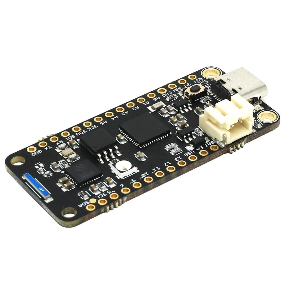

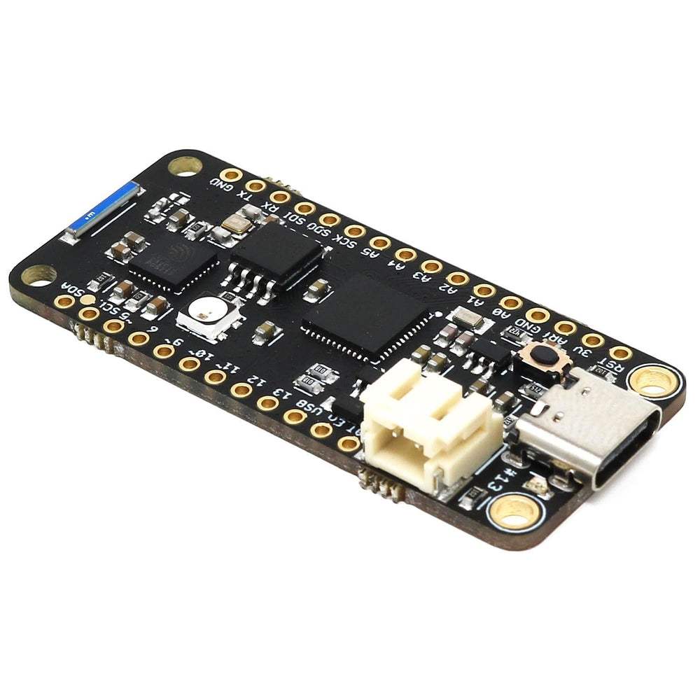
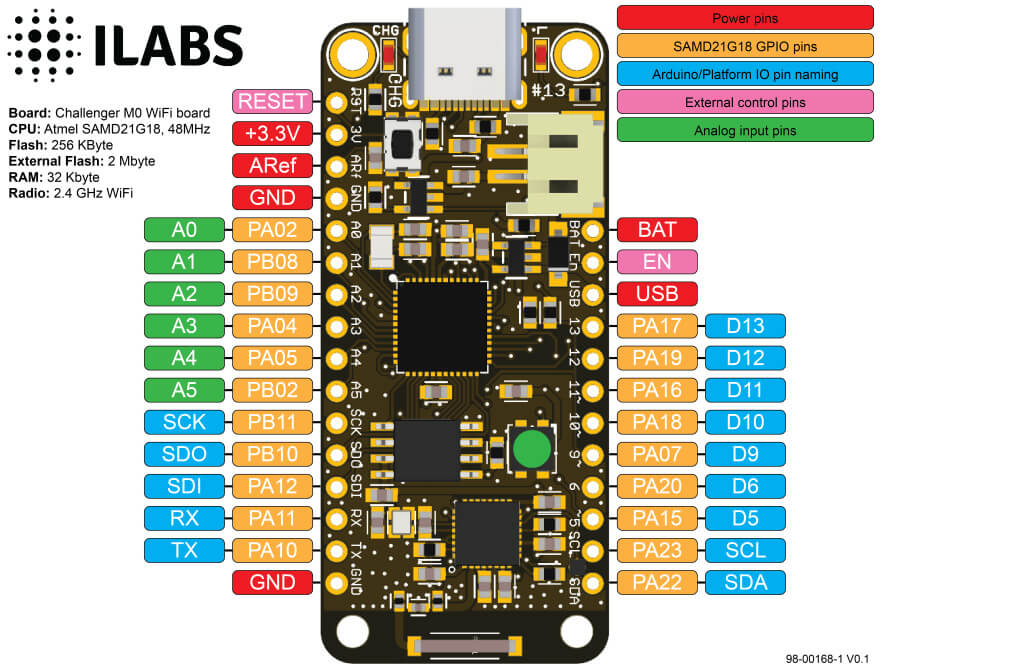
The iLabs Challenger M0 WiFi is an Arduino compatible Adafruit Feather format microcontroller board packed with loads of functionality for real time sensitive projects that require a WiFi connection.
For this board, we took Adafruit’s Feather M0 Express, which also happens to be a personal favourite of iLabs, and added an ESP8285 chip to it to give it extensive WiFi capability. With the experience that iLabs already had with the ESP8266, they knew it was the right way to go!
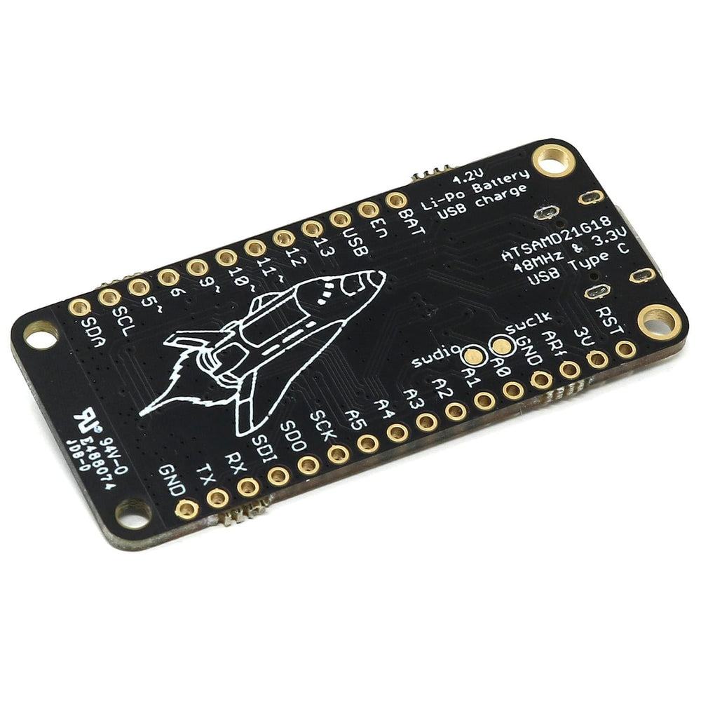
So the main controller of this board is the trusty SAMD21 with 256KByte of FLASH memory and 32KByte of SRAM. And just like the Feather M0 Express there is also an external 2Mbyte flash memory where you can store files systems or whatever that you need.
iLabs added an ESP8285 chip to this board. For those of you unfamiliar with this device, it is basically an ESP8266 device with an integrated 1MByte of flash memory. This allows us to have an AT command interpreter inside this chip that the main controller can talk to and connect to your local WiFi network. The communications channel between the two devices is an unused UART on the main controller and the standard UART on the ESP8285.
The ESP8285 chip comes pre-flashed with Espressif’s AT command interpreter stored in the internal 1MByte of the ESP8285. This interpreter support all of the operating and sleep modes of the standard ESP8266 framework which makes it easy to work with. Talking to the device is as easy as opening the second serial port (Serial2), resetting the ESP8285 and start listening for events and sending commands. To simplify this process we are also developing a library that is compatible with the standard ESP8266 environment.
The Challenger M0 WiFi board is 100% compatible with the Arduino framework. It has a unique board support package that fully supports all the features of the board. You can also install and run CircuitPython on the board if this is what you want to do.
While it is possible to run CircuitPython or micropython on this board we do not recommend it. The RAM size is just not enough to be able to take advantage of the libraries available to control the WiFi chip on board. We have made available a UF2 image that you can use to try it out but we will not push this to the main CircuitPython repo.
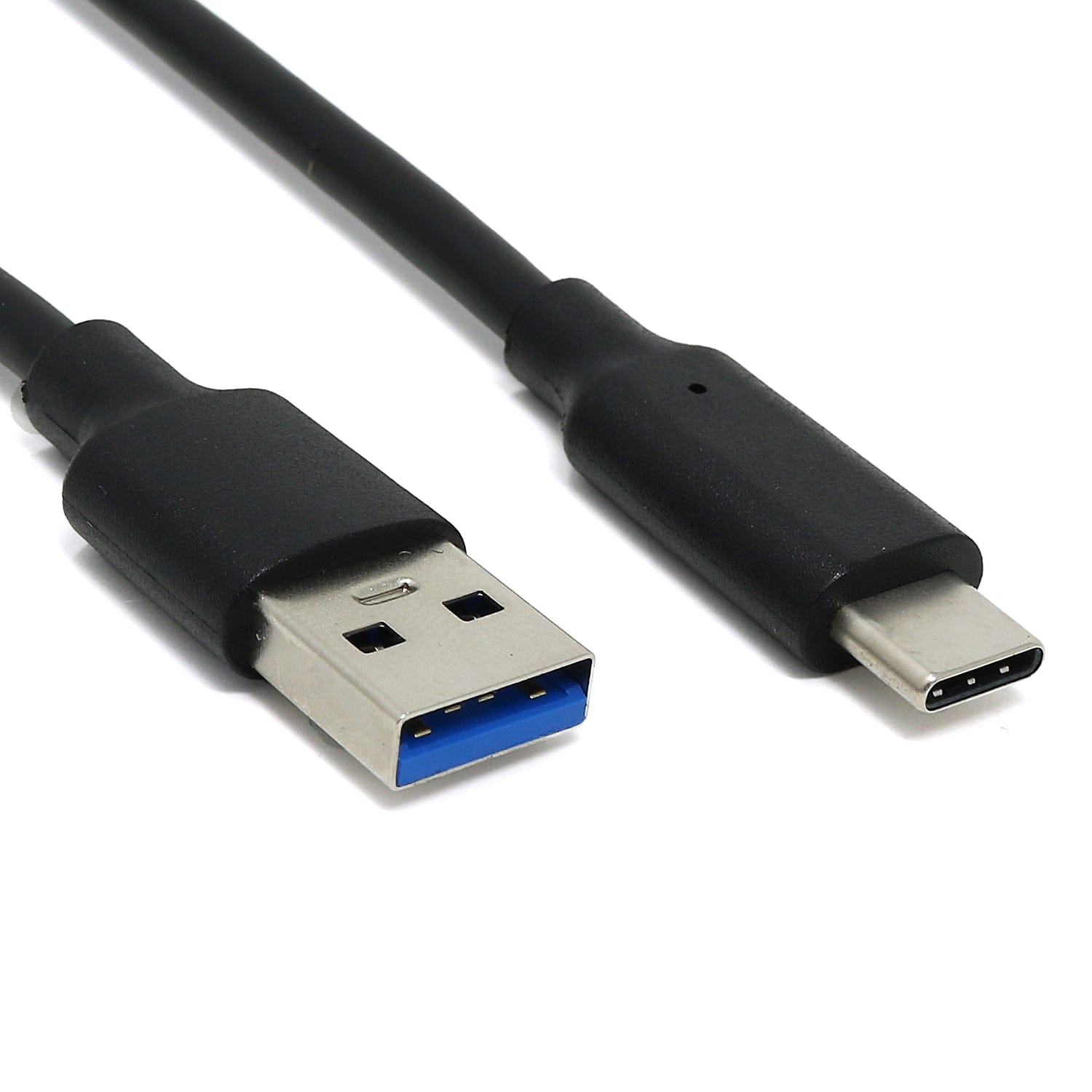
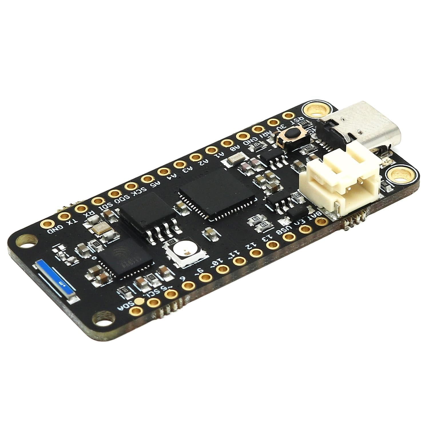
In recent years we have noticed that we are seeing more and more USB Type-C cables laying around the lab due to the fact that most new phones and accessories use them. So iLabs decided to go for a USB Type-C connector for this board. A bonus of this is that they are more durable and you don’t have to fiddle with the cable before plugging it in!
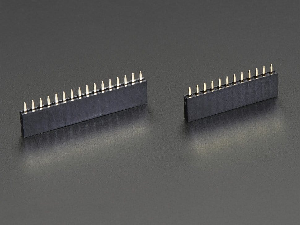
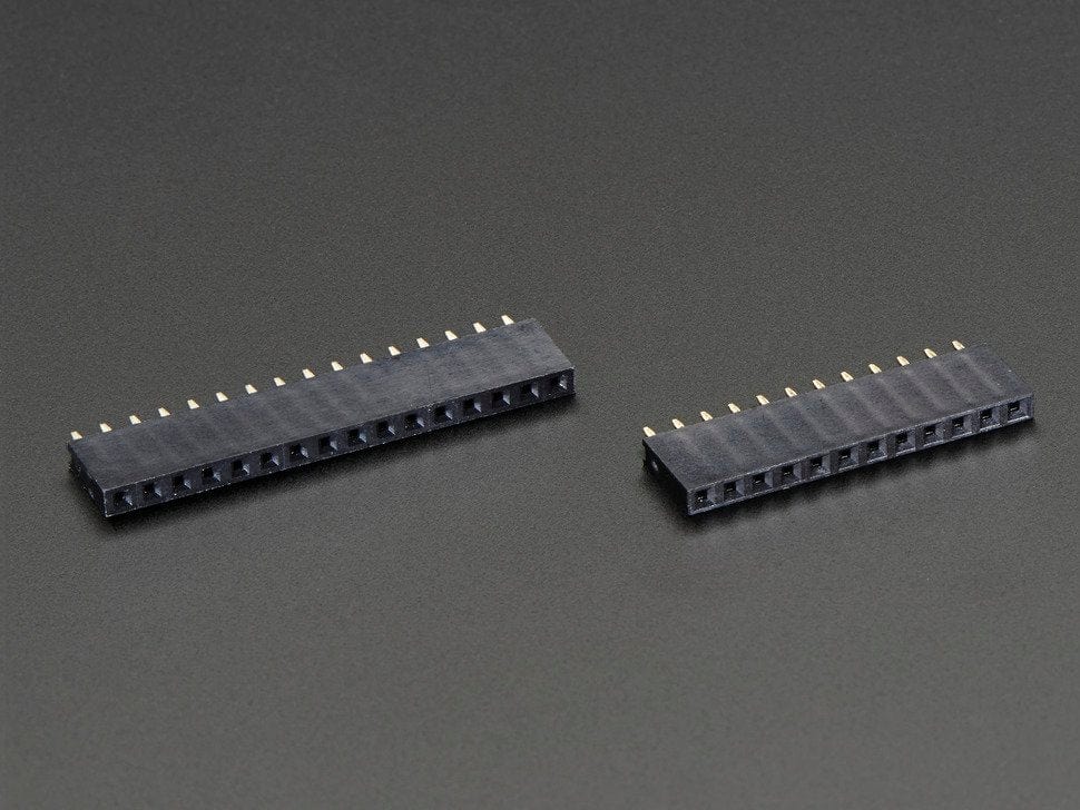
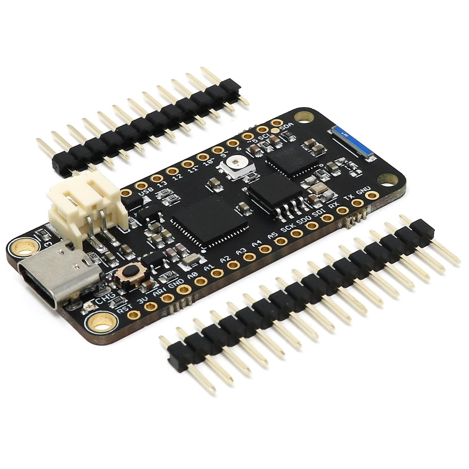
The board comes with loose headers that can be soldered to the board if your application requires it.
Main Processor
Network Processor
Board
Here’s a short step by step instruction on how to install the Arduino board support package that you need to be able to access all the features of the board.
That is it, when the process is done you are ready to select the “Invector Labs Challenger M0 WiFi” board in the board menu and start writing software for it.
While it is possible to run CircuitPython or MicroPython on this board we do not recommend it. The RAM size is just not enough to be able to take advantage of the libraries available to control the WiFi chip on board. We have made available a UF2 image that you can use to try it out but we will not push this to the main Circuitpython repo.
You can download this test firmware here.
Your payment information is processed securely. We do not store credit card details nor have access to your credit card information.

