Adafruit Infrared IR Remote Transceiver - STEMMA JST PH 2mm - 940nm Emitter + 38KHz Receiver
Price:
Sale price
£5.80
Stock:
Quantity:
Login / Signup
Cart
Your cart is empty


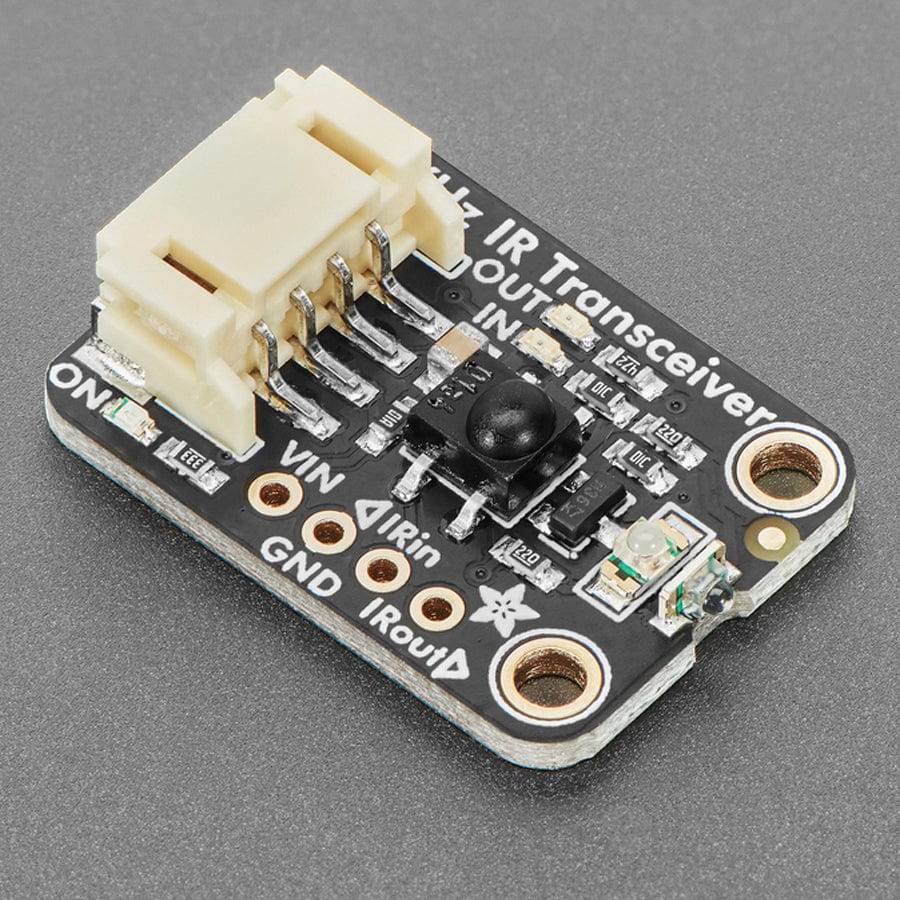
We've got a high-powered infrared emitter board, and a super-sensitive infrared remote receiver board - but why buy two boards when you can pick up one that does both? This board is the Adafruit Infrared Transceiver breakout, which can transmit and receive 940nm remote control data in one handy solder-free package.
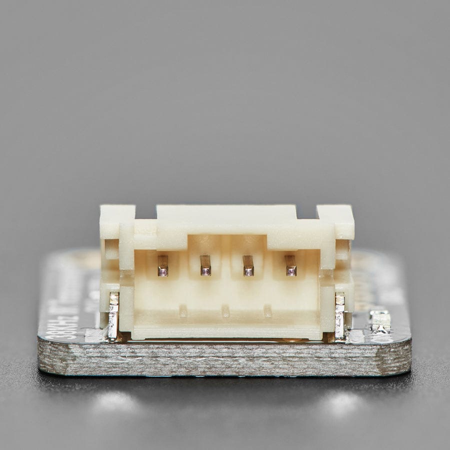
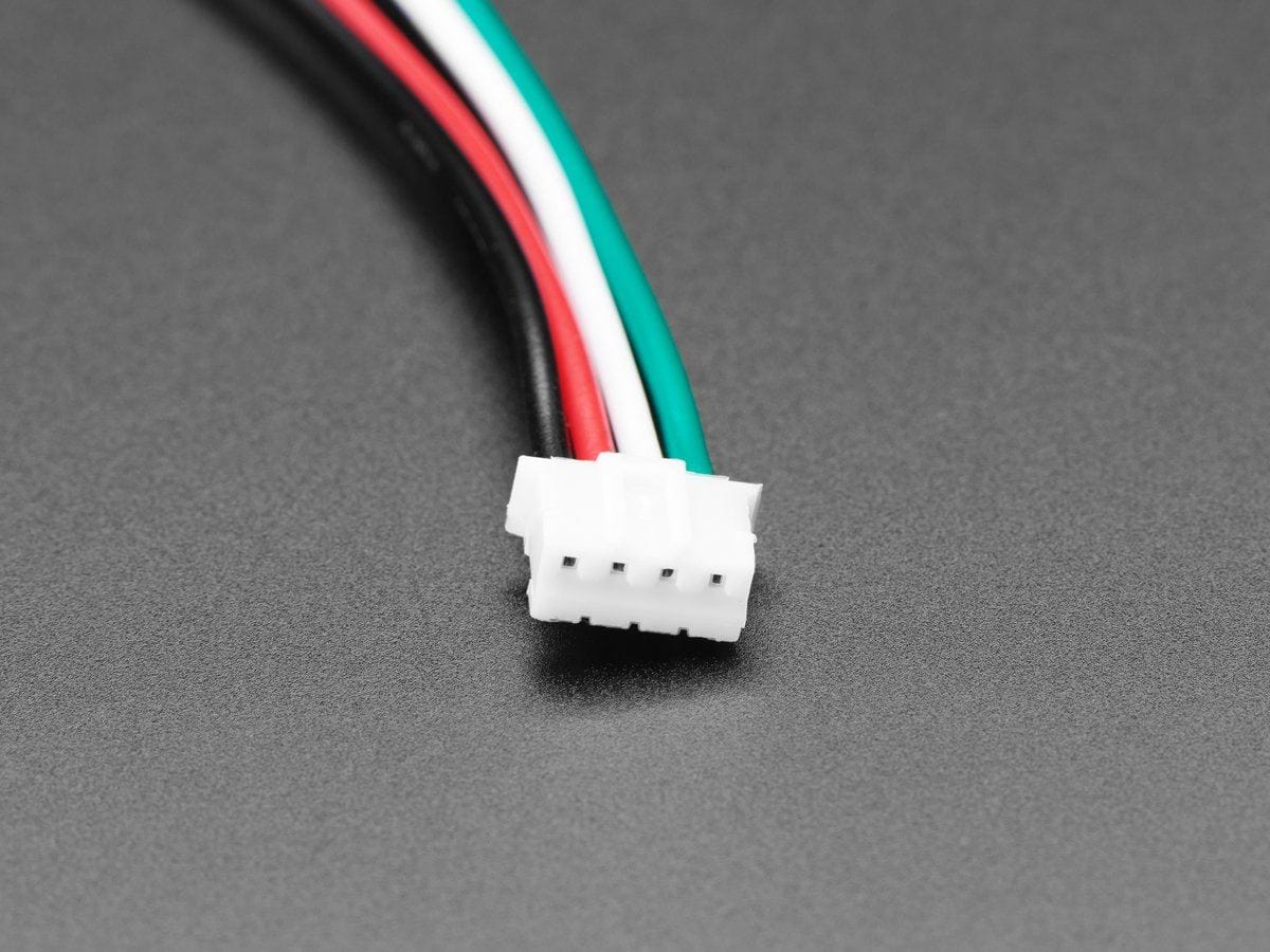
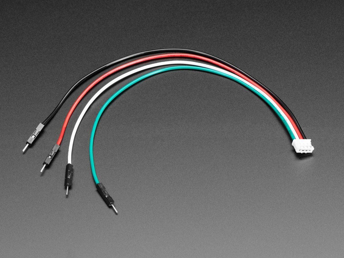
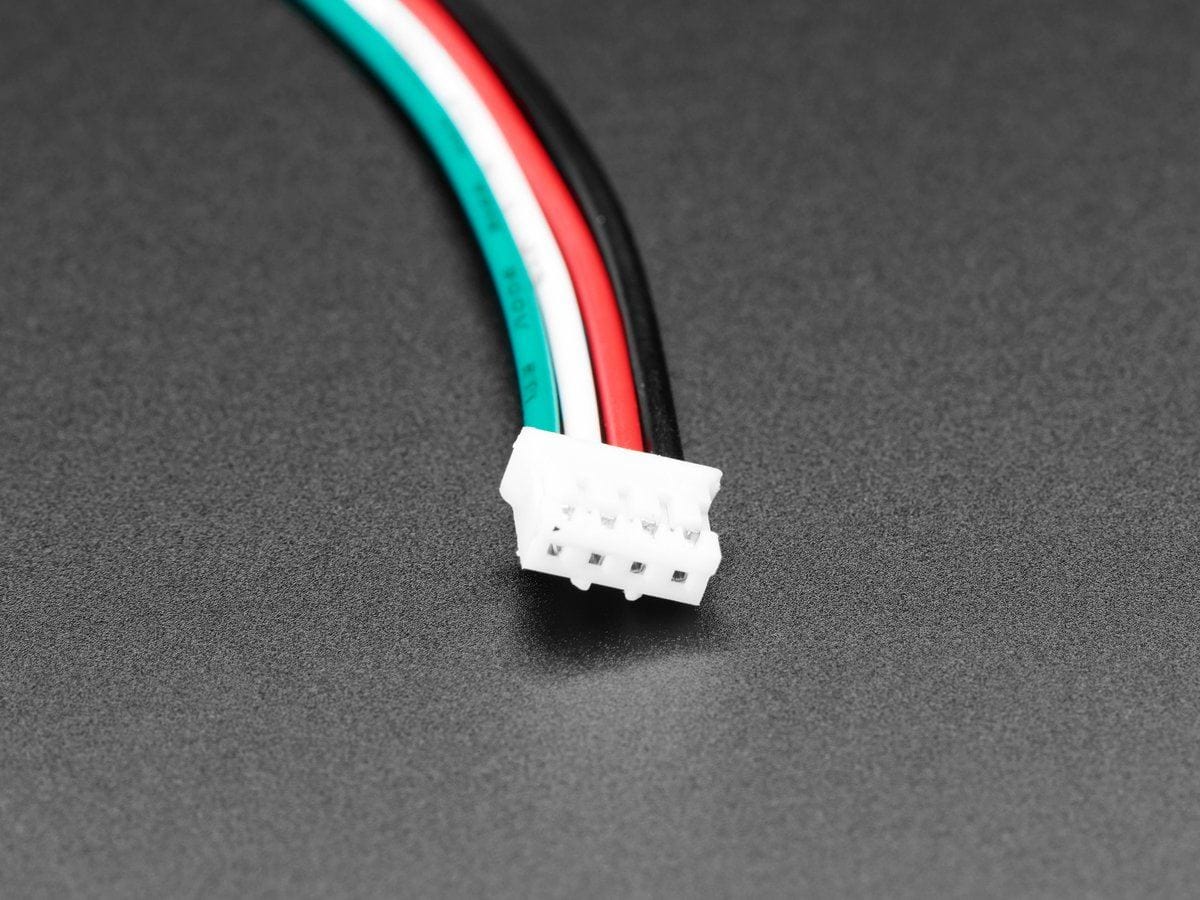
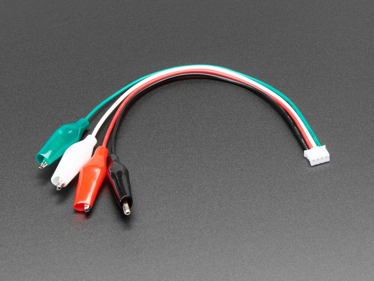
Please note: Just to make this board easy to use, we have both solder-able breakout pads and also a JST PH 4-pin cable. We often use JST PH cables for I2C but this board does not use I2C - the white wire is data from a microcontroller to be emitted over the IR LED, and the green wire is demodulated IR remote signal data to a microcontroller. The black wire is ground, red wire is 3V~5V power and logic level. This is not a STEMMA QT board!
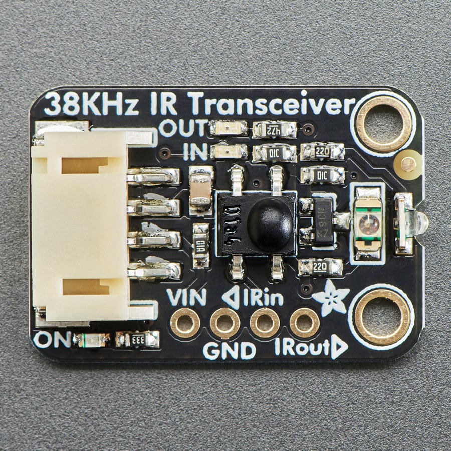
For the emitter half, we use the same schematic and set up as our "High Power IR LED Emitter" breakout, with an onboard N-Channel FET driver, to blast 100mA-200mA of current pulsing through each LED for 10+ meters of range! One LED is vertical and one is horizontal so you get tons of coverage. If powering with 5V, the board will draw about 200mA per LED (400mA total) when pulsing on. If powering with 3V the board will draw about 100mA per LED (200mA total). Since you can't see IR with a human eyeball, we have a small yellow LED labelled 'IN' that will blink when the IR LEDs are on.
For the receiver half, we use the same 'vertical' IR sensor in our "IR Receiver breakout" The sensor is designed to recognise remote control style modulated signal at 38KHz and 940nm wavelength. The demodulated IR envelope is piped out the OUT-labeled pin into your microcontroller which will then need to decode it. To make debugging easy, there's a second yellow LED labelled "OUT" that will blink when data is received.
Each STEMMA board is a fully assembled and tested PCB, but no cable. No soldering is required to use it, but you will need to pick up a 2mm pitch, 4-pin STEMMA JST PH cable. Alternatively, if you do want to solder, there's a 0.1" spaced header for power/ground/signals.
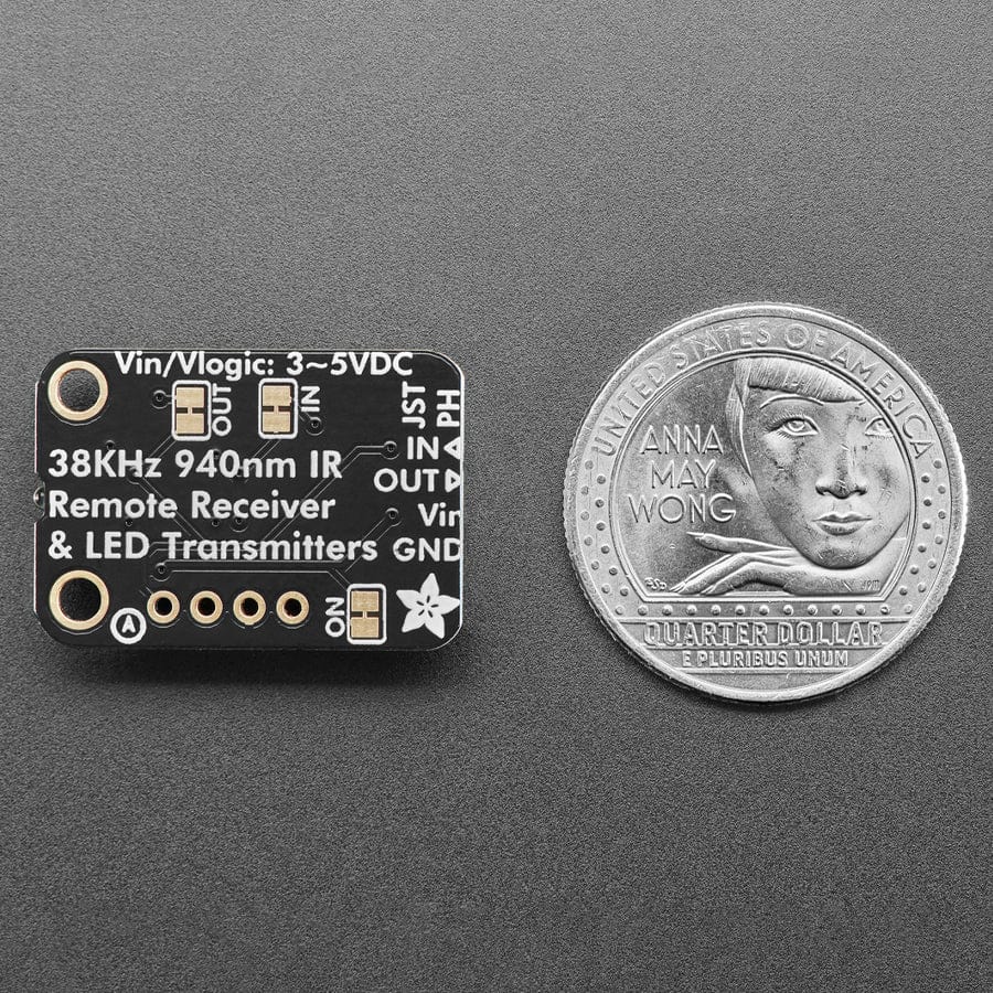
Note that this board is specifically for receiving 940nm 38KHz IR remote control signals - it isn't going to work for proximity/distance sensing or other frequency signals. The signal must be read by a microcontroller that has pulse-input reading capabilities - basically, just check that it supports common IR Receiver connectivity and decoding. Sometimes you need to use special code or pins.
Your payment information is processed securely. We do not store credit card details nor have access to your credit card information.