RP2040 Interfacer (UART/I2C)
Price:
Sale price
£5
Stock:
Quantity:
 Skip to content
Login / Signup
Cart
Your cart is empty


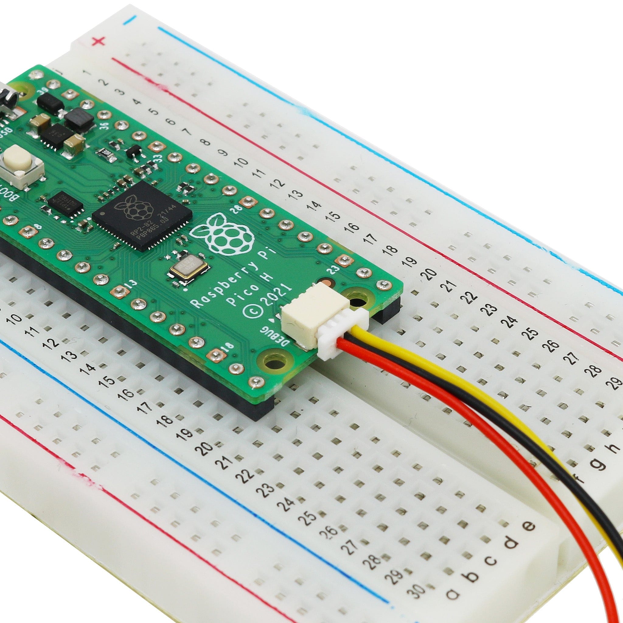
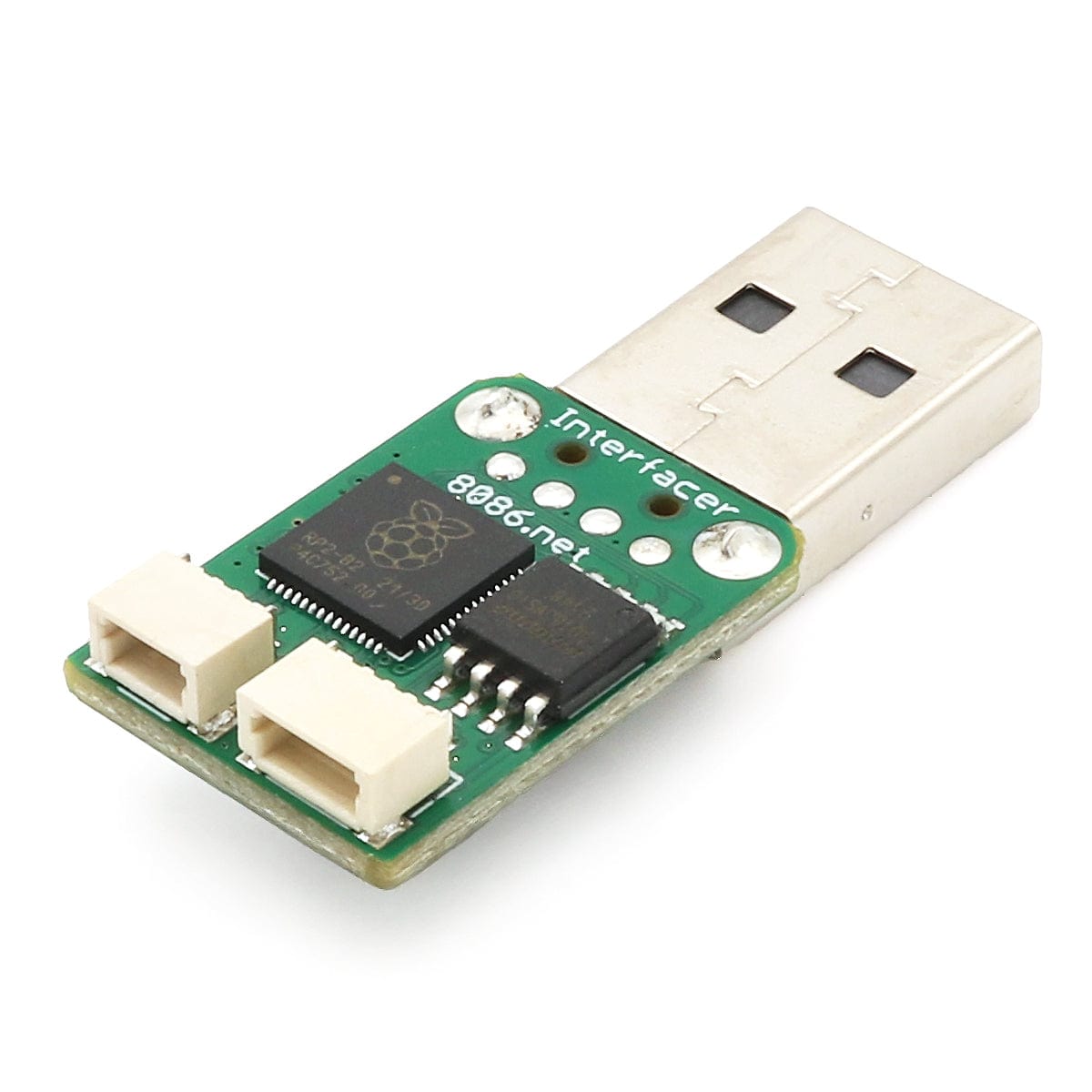
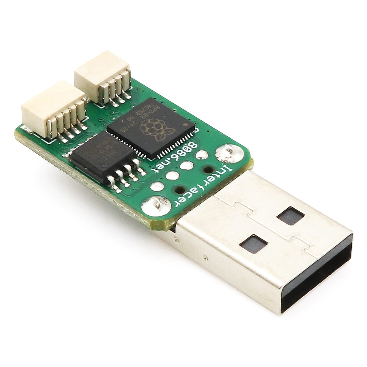
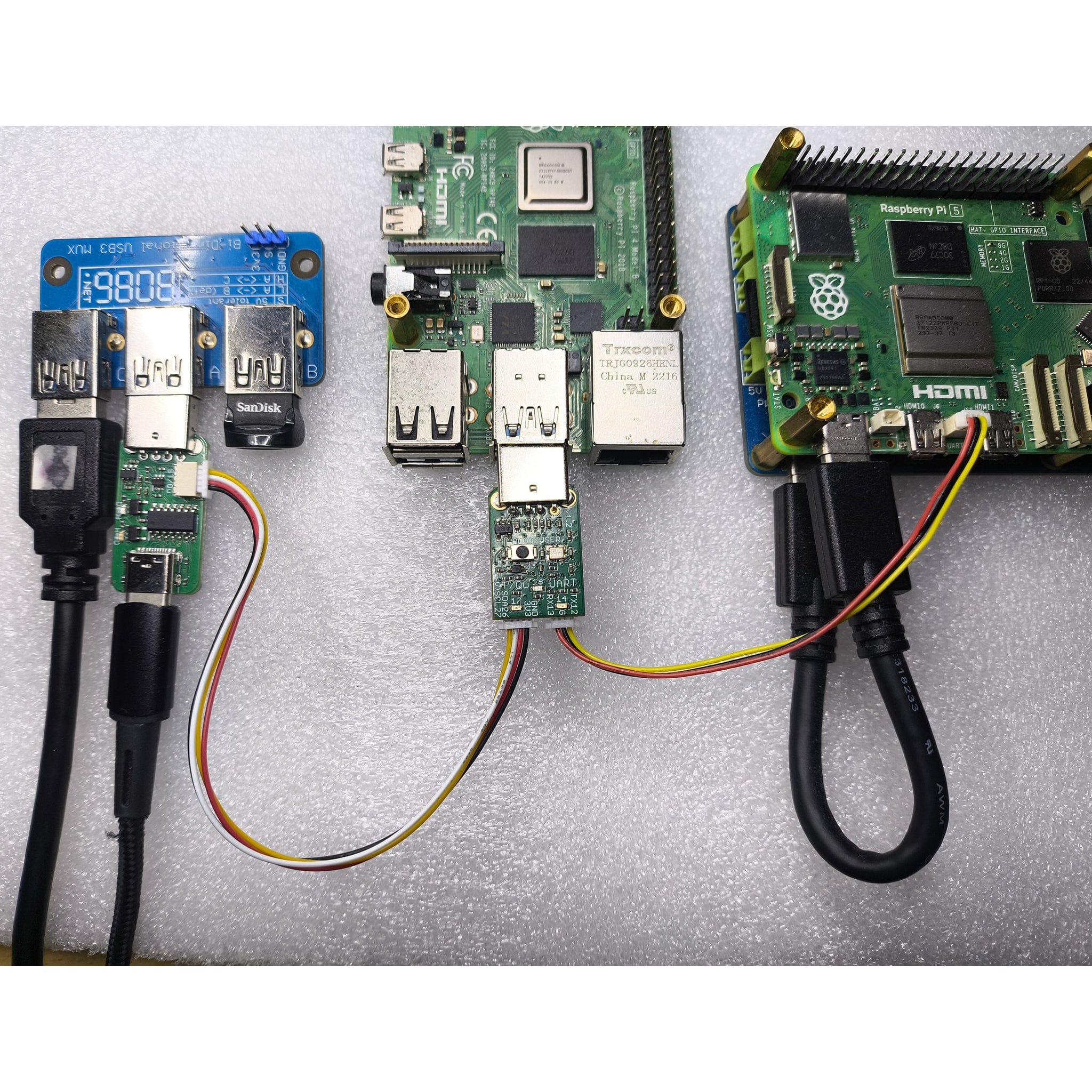
The RP2040 Interfacer is a small low-cost USB to UART and I2C Adapter (both 3.3V) powered by an RP2040 microcontroller that plugs straight into a USB Type-A socket. Being powered by the RP2040 with 2MB FLASH it can be used with CircuitPython or Pico C SDK based firmware.
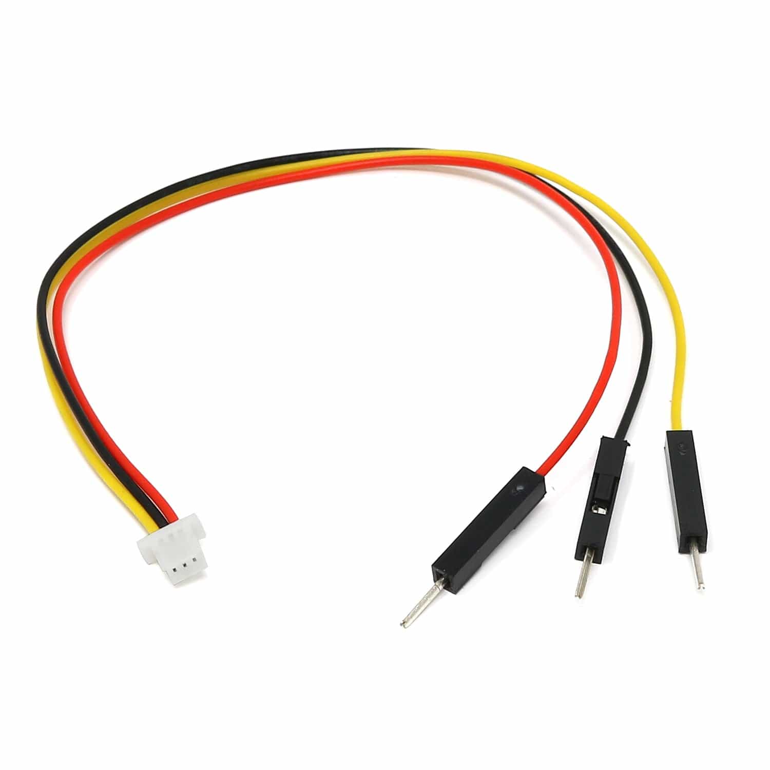
The serial UART connector is a 3-pin JST SH compatible socket as used on the Raspberry Pi 5 UART port.
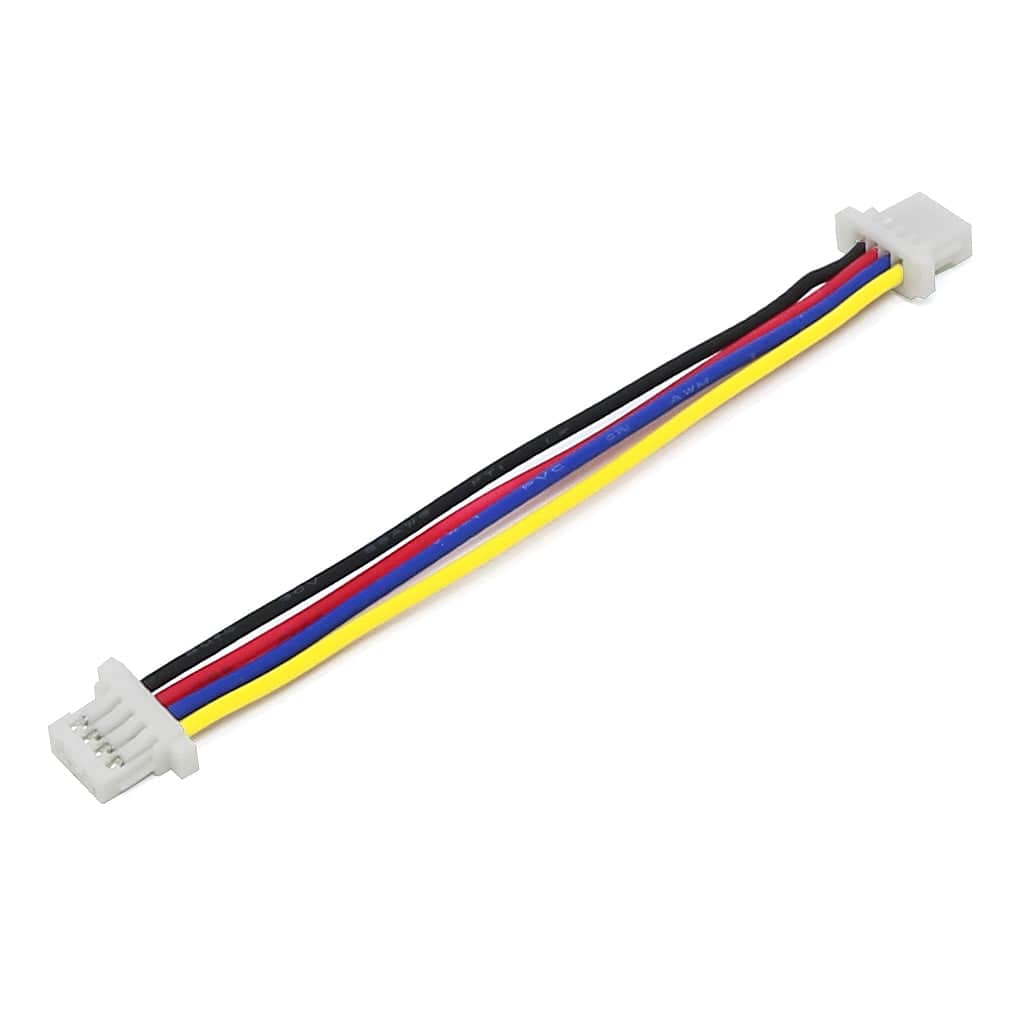
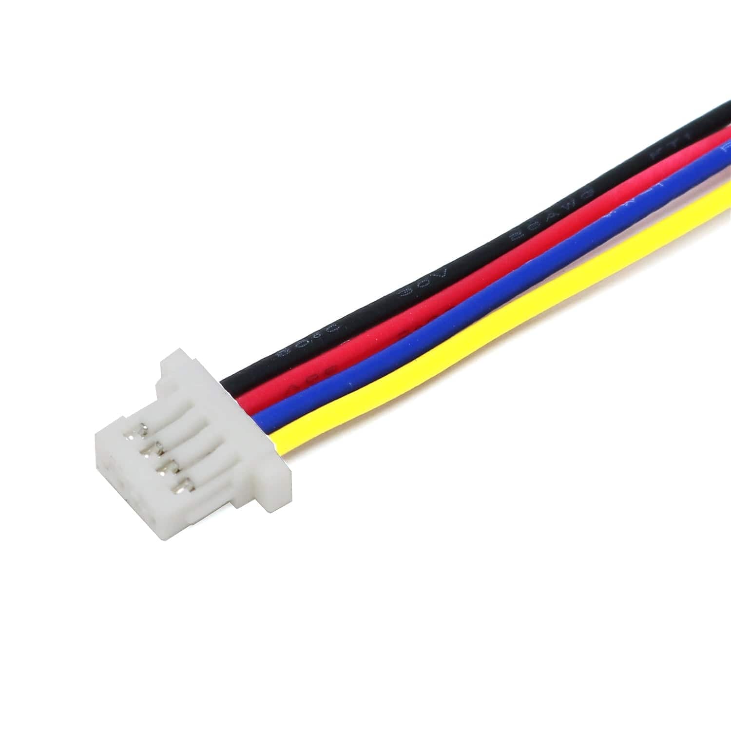
The I2C ST/Qw connector is a 4-pin JST SH compatible with (3.3V) Qwiic/STEMMA QT. The SCL/SDA lines also have 1K resistors connected to additional GPIO lines allowing each one to have either pull up/down resistor enabled in software. The ST/Qw GPIO pins used are capable of analogue input allowing them to be used for non I2C uses, and when combined with the 1K pull resistors, can be used to measure and detect external pull up/down resistors.
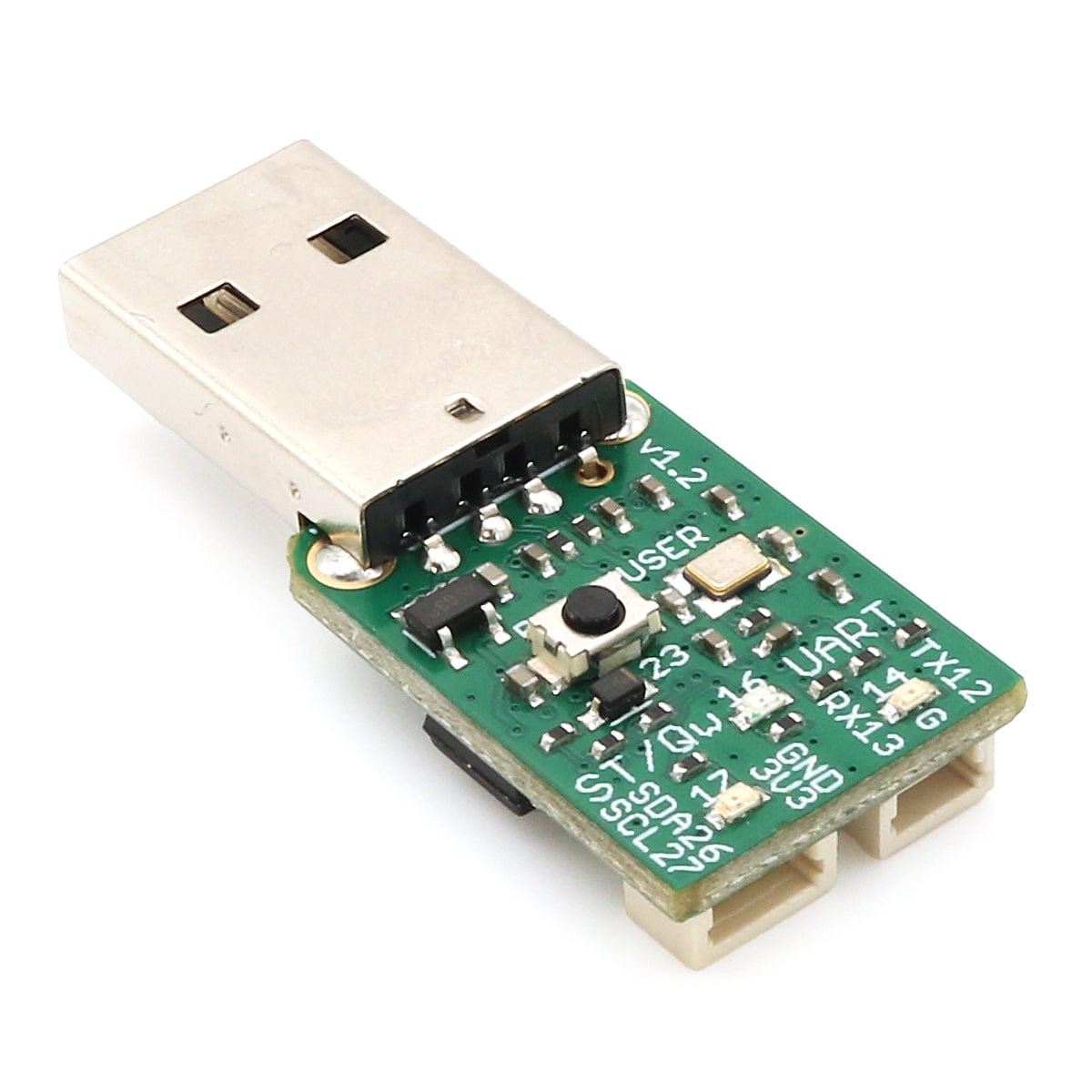
On the reverse side of the connectors, there are three LEDs. In the middle is a red LED and over both UART and ST/Qw connectors are orange LEDs.
The RP2040 BOOTSEL button is dual-purpose, once the RP2040 has started up it can be used for user input.
You can also use a USB-C to USB-A adapter to allow the Interfacer to connect to many mobile phones for USB CDC Serial UART access (where supported)!
The GPIO pin numbers for the connectors, LED, and button (as listed below) are also labelled on the PCB itself for quick reference
| GPIO | Usage |
| GP12 | UART TX |
| GP13 | UART RX |
| GP14 | UART orange LED |
| GP16 | Red status LED |
| GP17 | ST/Qw I2C orange LED |
| GP18 | 1K Resistor to SDA |
| GP19 | 1K Resistor to SCL |
| GP23 | USER Button (active LOW) |
| GP26 | ST/Qw I2C SDA/A0 |
| GP27 | ST/Qw I2C SCL/A1 |
To upload the usb_interfacer_bridge firmware to the USB Interfacer:
The board is also supported by CircuitPython the firmware can be downloaded from the CircuitPython Download page.
Cables not included
Your payment information is processed securely. We do not store credit card details nor have access to your credit card information.