Adafruit PiCowbell CAN Bus for Pico - MCP2515 CAN Controller
Price:
Sale price
£12
Stock:
Quantity:
 Skip to content
Login / Signup
Cart
Your cart is empty


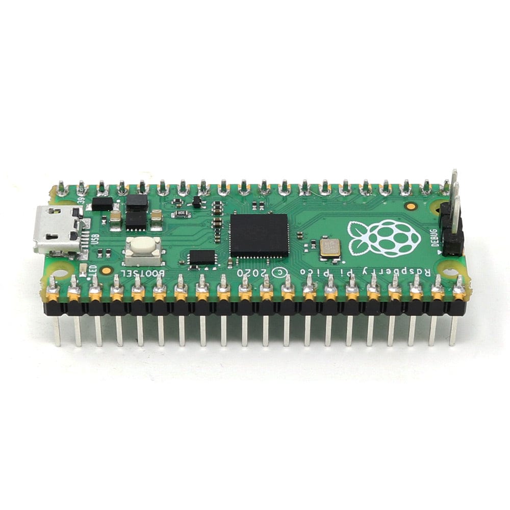
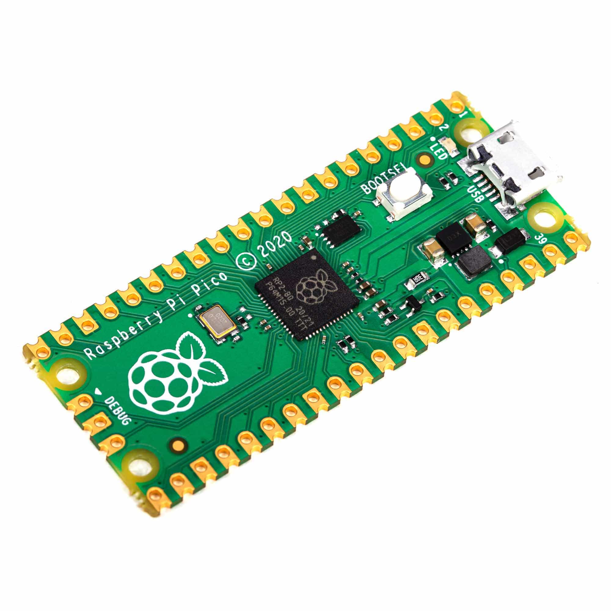
Ding dong! Hear that? It's the PiCowbell ringing, letting you know that the new Adafruit PiCowbell CAN Bus is in stock and ready to assist your Raspberry Pi Pico and Pico W project connect to CAN bus networks for automotive or robotics projects.
CAN Bus is a small-scale networking standard, originally designed for cars and, yes, busses, but is now used for many robotics or sensor networks that need better range and addressing than I2C and don't have the pins or computational ability to talk on Ethernet. CAN is 2 wire differential, which means it's good for long distances and noisy environments.
Messages are sent at about 1Mbps rate - you set the frequency for the bus and then all 'joiners' must match it, and have an address before the packet so that each node can listen in to messages just for it. New nodes can be attached easily because they just need to connect to the two data lines anywhere in the shared net. Each CAN device sends messages whenever it wants, and thanks to some clever data encoding, can detect if there's a message collision and retransmit later.
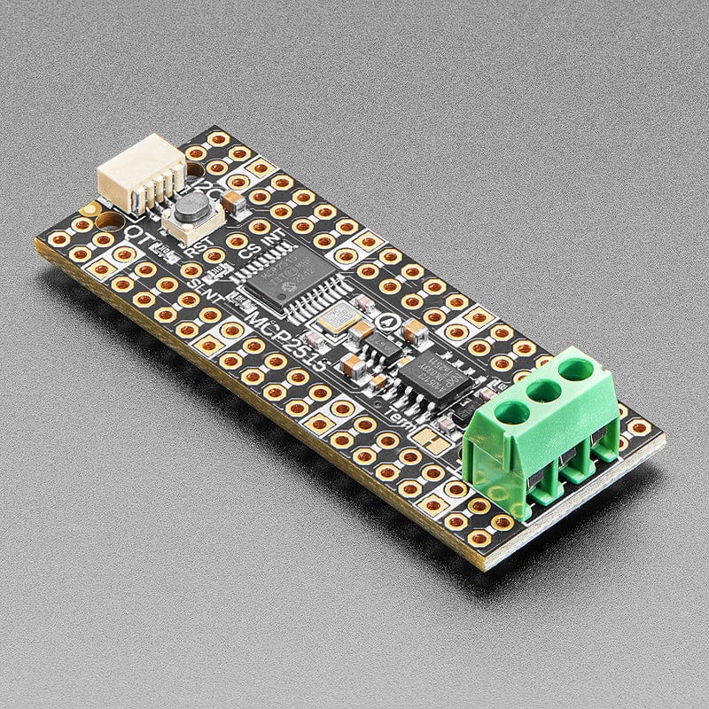
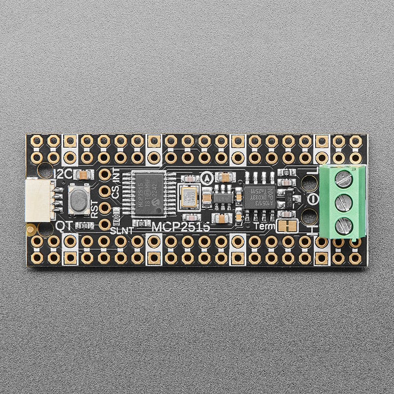
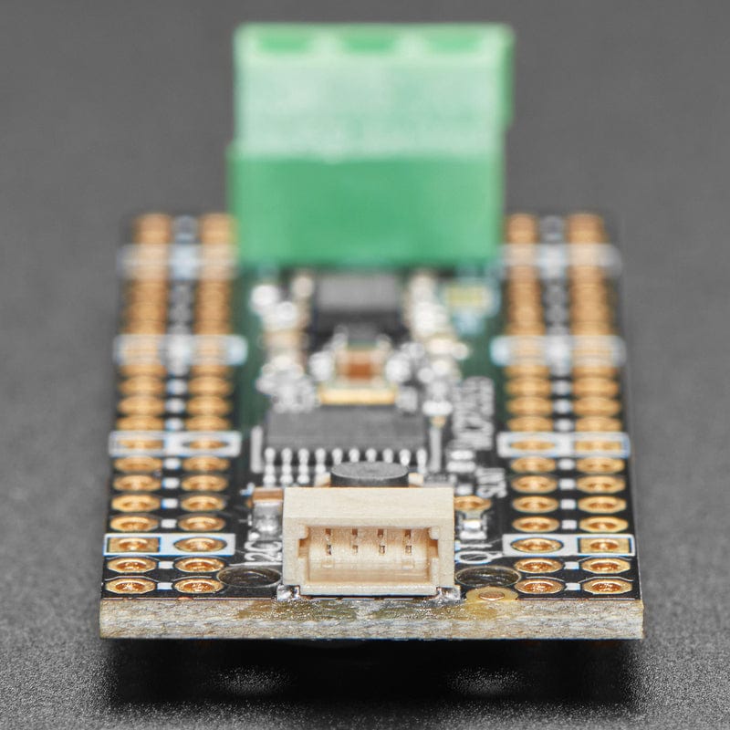
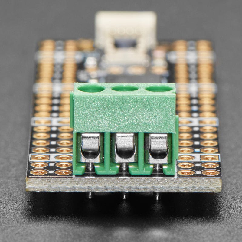
If you'd like to connect your Raspberry Pi Pico to a CAN Bus, the Adafruit PiCowbell CAN Bus has an MCP2515 controller and TJA1051/3 transceiver! The controller is the MCP2515, an extremely popular and well-supported chipset with drivers in Arduino and CircuitPython and only requires an SPI port and two pins for chip-select and IRQ. Use it to send and receive messages in either standard or extended format at up to 1 Mbps.
We've added a few nice extras to this PiCowBell to make it useful in many common CAN scenarios:
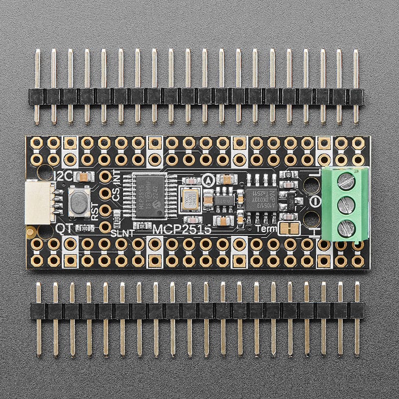
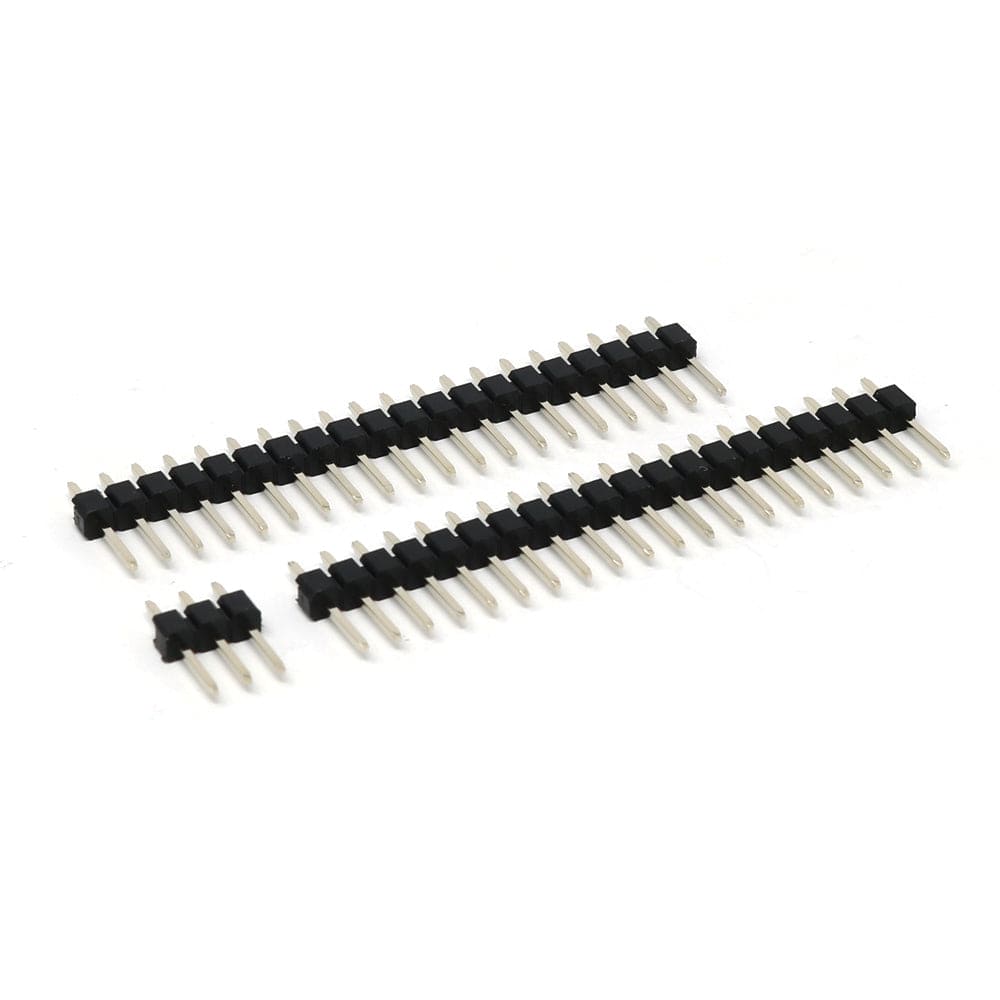
Each order comes with an assembled PCB and header. You will need to solder in the header yourself, but it's a quick task.
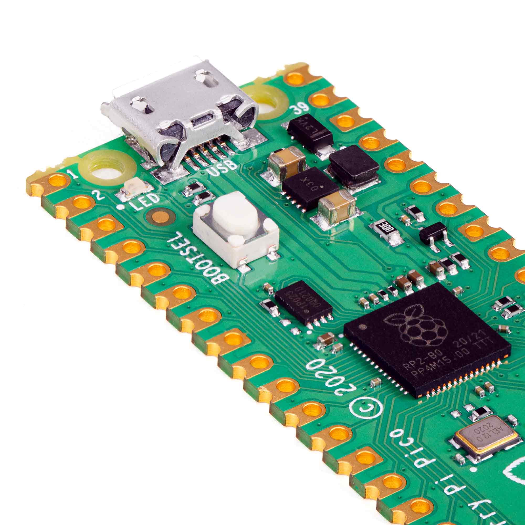
Please Note! There are a lot of possible configurations, and we stock various headers depending on how you want to solder and attach them. Especially if you want the Pico on top so that the BOOTSEL button and LED are accessible.
The PiCowbell CAN Bus provides you with:
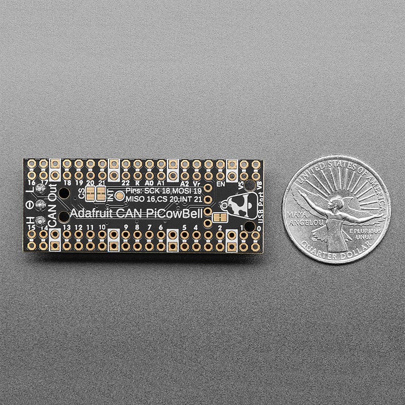
If using the Philhower Arduino core, the Wire peripheral is already set up to use IO4 and IO5, and SPI defaults on IO16, IO18 and IO19. If using CircuitPython or MicroPython, you'll need to let the code know to look at 4+5 for SDA+SCL pins and configure the SPI port for SCK=18, MOSI=19 and MISO=16.
Your payment information is processed securely. We do not store credit card details nor have access to your credit card information.