Ryanteck Debug Clip - Soldering Guide
This guide will show you step by step how we recommend to solder the debug clip with ease. If you prefer to solder components in a different order then that's fine! This is how we found it the easiest to solder without much trouble.
Checking Components
Your kit should include the following:
- 1 - RTK-000-006 PCB
- 1 - MCP2221 Chip
- 1 - 0.5A Polyfuse (Yellow component that looks more like a capacitor)
- 1 - Diode
- 2 - 47Ohm Resistors
- 1 - USB B Socket
- 1 - Red LED
- 1 - Green LED
- 1 - 2 Pin Header
- 1 - 2 Pin Jumper
Preparing To Solder
You will require the following tools to solder:
- Soldering Iron! - Most should solder fine for this kit.
- Solder! - I use Lead Free Solder
- Wire Cutters - used for snipping the legs after soldering. A nice pair of wire cutters are cheap and will do the job best.
You may also find the following useful!
- Blu-Tack - Handy for keeping the PCB in place at points.
- Soldering Iron Cleaning Equipment - I use brass shavings to clean my iron's tip and they work pretty well and cost around £5 for a pot. If you don't then a sponge which normally comes with your iron should do the job well.
- Bright light - I find having a very bright light over what I'm soldering helps a lot. Normally I can see a bridge very clearly if I do one. (I use one which came with a mini photobooth kit).
- Safety Glasses - It is recommended to wear safety glasses of some type, especially when trimming the leads on components.
- A breadboard or sponge / foam - I find for soldering the 2 pin header a breadboard, sponge or foam helps to keep it in place.
Written Guide
Step 1 - Resistors & Diode
Start by bending the legs on the two resistors and diode to the rough size of the PCB

Next push the two resistors into the PCB and the diode making sure the line on the diode matches the one on the PCB.

Finally solder all of the components and trim the leads down to the correct length. If you like you can then re-heat each joint to have a nicer finish.
Step 2 - IC
Next we need to solder the Integrated Circuit.
Begin by carefully bending the legs on the chip. You can either use an IC bending tool, two bits of wood or carefully do it by hand. Do it in small increments if by hand and check to see if it can fit into the PCB each time. You should then be able to push it into the PCB.

Finally solder the IC onto the PCB.

Step 3 - 2 Pin header
Now we are going to solder the 2 pin header. You can do this at the end if you prefer but I find now is the best time to solder it.
Place the pin header carefully into a breadboard, Sponge or piece of foam and then place the PCB onto the header.

While holding the PCB in place then solder the header. Don't leave the iron on it for too long or it may make one pin solder at an angle to the other.
Step 4 - USB Socket
I find that the best component to solder next is the USB socket as its the tallest components and makes soldering the poly fuse and LEDs easier.
Begin by pushing the USB socket into the location on the PCB and then solder the 4 USB pins and the 2 ground pins at either side to help keep it in place.

Step 5 - Polyfuse
Next place the polyfuse into its location on the PCB and bend the legs to keep it in place.

Now solder the polyfuse and snip the leads.

Step 6 - LEDs
Finally place both of the LEDs into the PCB with the positive leads (longer) both in the middle towards the + symbol. Then bend the leads slightly at the base to keep them in place while soldering.

And then solder the LEDs and snip the legs off of them.

Step 7 - Finishing Up
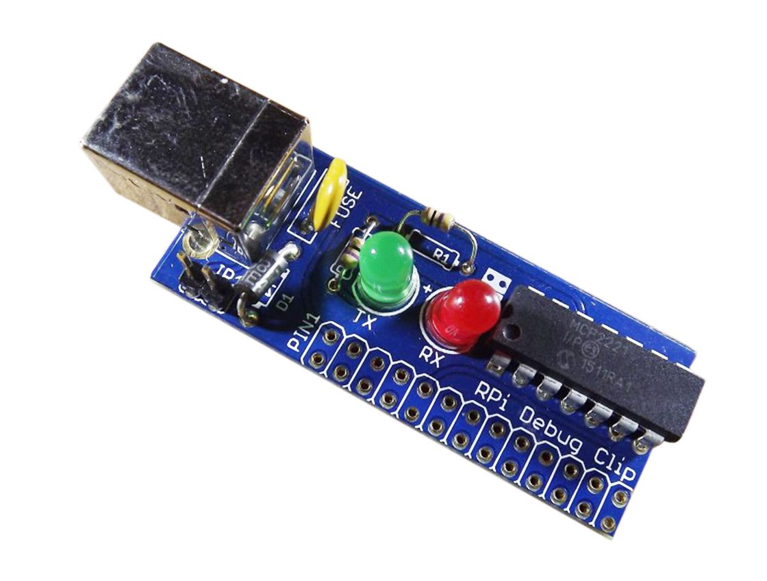
Congratulations you now have a fully soldered debug clip.
All of the solder joints should be shiny, if you have missed any then now is the time to re-solder any joints and require it.

And then place the jumper onto the 2 pin header on the PCB. You can have the jumper connected to power your Raspberry Pi via the 5V supply on from your USB port or have it just kept on one pin to have the Pi powered by its own source such as another USB charger, battery bank or batteries.


