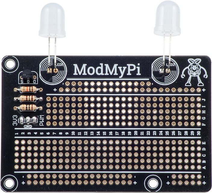
Pi Monster Lighting Board Assembly
Bill of Materials
- 1x PCB
- 2x 10mm LED
- 4x Resistors
- 1x 10k ohm
- 1x 100 ohm
- 1x 10 ohm
- 1x 27 ohm
- 1x 2N7000 Transistor
- 1x 3x1 0.1” pin header
- 3x F/F Jumper Wires
- 3x 1” hex aluminium standoffs
- 3x ¼” screws
PCB Assembly
- Get the PCB, make sure the “ModMyPi” text is at the top
- Solder the 2N7000 transistor on to the PCB section labelled D G S, making sure to get the transistor orientation correct. The flat side of the transistor should be facing the letters ( D G S ) on the PCB.
- Solder the 3x1 pin header on to the PCB. The short pins should be inserted from underneath and soldered on top (the side with the “ModMyPi” text). The long pins should now be facing down, underneath the PCB.
- Solder the 10k ohm resistor on to the PCB section labelled PD1
- Solder the 100 ohm resistor on to the PCB section labelled BR1
- To illuminate the LEDS to their brightest, follow part 6a. To illuminate the LEDs to a more ambient glow, follow part 6b
- 6a. Solder the 27 ohm resistor on to the PCB section labelled LR1 (when connecting the 3v3 pin up to the RPi, connect it to a 5v source)
- 6b. Solder the 10 ohm resistor on to the PCG section labelled LR1 (when connecting the 3v3 pin up to the RPi, connect it to a 3.3v source)

- Align the LED’s so that the short leg goes into the square LED hole on the PCB
- Bend the LED head 90 degrees down, so that the LED is facing away from the “ModMyPi” text.
- Solder the LED’s in place

Hooking the PCB up to your Pi
- Connect the GND pin from the PCB to a GND pin on the GPIO (pin #6)
- Connect the PWM pin from the PCB to GPIO18 (pin #12)
- If you soldered the 27 ohm resistor to the PCB in step 4a of PCB Assembly, follow step 3a. If you soldered the 10 ohm resistor to the PCB in step 4b of PCB Assembly, follow step 3b
- 3a. Connect the 3V3 pin from the PCB to a 3.3v source (pin #1)
- 3b. Connect the 3V3 pin from the PCB to a 5v source (pin #2)
- If you have a Pi Head Case then mount the PCB above the Raspberry Pi using the standoffs provided. Make sure the LED’s are facing the “face” side of the case.
Making the lights glow
- Install wiringPi
- Download and uncompress the master.zip archive to your Raspberry Pi:
wget https://github.com/modmypi/Mean-Crafty-Pi-Monster/archive/master.zip unzip master.zip
- You can either compile the code by typing 'make' or you can simply use the 'mcpm' binary that's including in 'master.zip' by making it executable.
chmod +x mcpm
sudo ./mcpm&
Make the light glow on boot
- Create the auto-start script
sudo nano /etc/init.d/mcpm.sh - Paste the script below in the editor and save it. The script assumes that 'mcpm' was compiled in the '/home' folder. Adjust the auto-start script according to the actual location of the executable if it's not in '/home'.
#! /bin/sh
# /etc/init.d/mcpm.sh
# http://wiki.debian.org/LSBInitScripts
### BEGIN INIT INFO
# Provides: mcpm
# Required-Start: $local_fs $syslog
# Required-Stop: $local_fs $syslog
# Default-Start: 2 3 4 5
# Default-Stop: 0 1 6
# Short-Description: Basic startup & shutdown script
# Description: Starts and stops an application on boot & shutdown
### END INIT INFO
# Commands listed below will always run
# System command handler
case "$1" in
start)
# start the application
echo "Head case lights on"
/home/mcpm&
;;
stop)
# stop the application
echo "Head case lights off"
killall mcpm
;;
help)
echo "Usage: /etc/init.d/mcpm.sh {start|stop}"
exit 1
;;
esac
exit 0 - Make the script executable and test the commands
chmod +x /etc/init.d/mcpm.sh
/etc/init.d/mcpm.sh help
/etc/init.d/mcpm.sh start
/etc/init.d/mcpm.sh stop - Add mcpm.sh to the list of programs to start on boot
update-rc.d mcpm.sh defaults - If you want to remove it from the list of programs to start on boot, do:
update-rc.d mcpm.sh remove - That's it! Now, the head lights will turn on and glow as soon as the Raspberry Pi boots up :)


