

Maker Advent Calendar Day #4: Amazing Analogue!
Welcome to day four of your 12 Projects of Codemas Advent Calendar. Today we’ll be playing with analogue inputs using a potentiometer and combining this with some of the components we've already played with.
Our code so far has been ON/OFF or HIGH/LOW using digital inputs and outputs. With today's component, we're going to explore analogue inputs which work in a different way.
Tip: You'll find that some people in the maker world use "analog'"and others prefer "analogue" - it's all the same thing.
Box #4 Contents
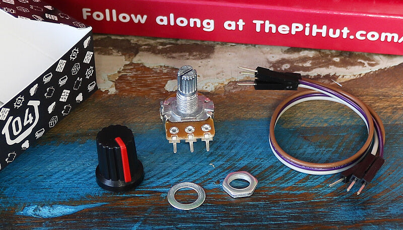
In this box you will find:
- 1x 10k Potentiometer
- 1x Potentiometer knob
- 1x Washer (may be fitted to the potentiometer already)
- 1x Nut (may be fitted to the potentiometer already)
- 3x Male to male jumper wires
Today’s Project
Today we're exploring the wonderful world of analogue.
Until now, we've been using digital signals with the buttons and LEDs in our calendar. Digital signals are strictly a 1 or a 0, HIGH or LOW, ON or OFF. It's one or the other and nothing in between.
Analogue signals offer a wide range of numbers to represent values instead, which is much more suitable for sensors, dials and similar components.
Think of digital as a light switch - it's either on or it's off. Think of analogue as a volume dial on a stereo - you can twist the dial to gradually turn the volume up and down by small amounts.
Our potentiometer can pass these analogue signals (in the form of voltage) to our Raspberry Pi Pico, giving us a gradual input with a wide range of values for us to play with in our code.
What is a Potentiometer?
A potentiometer is a variable resistor.
Our calendar already included traditional resistors for the LEDs, but these were at a fixed value offering a specific amount of resistance. A potentiometer is a resistor that can have its value changed (by turning the knob).
The potentiometer in your box is a 10K potentiometer, meaning it can be set anywhere from 0 ohms to 10,000 ohms (resistance is measured in ohms).
The way we're going to wire our potentiometer allows us to use it to send a varying voltage value to our Raspberry Pi Pico, which some special pins can read, convert and provide a value we can use in our projects.
We're going to explain those pins in a few moments, but for now let's get the circuit built.
Construct the Circuit
Make sure your Pico's USB cable in unplugged before changing the circuit.
Grab your potentiometer, slide the flat washer over the dial and then screw on the included nut (these may already be fitted).
Then, with the potentiometer legs facing downwards, turn the dial all the way to the left and fit the knob with the coloured line pointing bottom-left (like a radio that's turned all the way down).
Leave the LEDs and GND wire (in the blue lane) in place from yesterday's box, but remove the buttons and all other parts. This is our starting point:

Now grab the mini breadboard and fit the potentiometer to the front edge (facing you). Our diagram uses a generic potentiometer image, however as you have a fancy panel mount version, your pins will have a hole space between them:

Next we need to connect the potentiometer to our circuit.
The right pin needs to connect to the 3V3(OUT) pin (physical pin 36), the middle pin to GPIO 27 (physical pin 32) and the left pin to GND (use the blue lane as we already have that connected to GND for the LEDs).

Activity 1: Printing analogue values
Let's start with a simple program that continually prints the analogue reading from our potentiometer.
We're specifically using GPIO27 as this is one of the Pico's ADC pins. But what is an ADC?
ADC Pins
If you look at our Pico pin map again, you'll see that there are three dark green ADC pins available on the right - GPIO26, 27 and 28 (physical pins 31,32 and 34).
An ADC is an Analogue to Digital Converter. The ADC pins on our Pico have the special ability of being able to convert an analogue input into a digital form we can use. We have to import ADC in our code to use this feature.
Note: You'll also spot ADC_VREF and AGND pins, but we're not going to go into those pins in this calendar as we don't strictly need to use those for our example - we'd rather not overcomplicate things whilst we're still learning.
The Code
The code below imports ADC and sets GPIO27 as an ADC pin, then we start a while loop which prints the potentiometer's value every second.
The read_u16 part does this, taking the varying voltage applied to the pin from the potentiometer and scaling this to range of usable output values between 0 and 65535.
(For those who want to get technical - the Pico's ADC pins are 12-bit, however MicroPython scales this to a 16-bit range which is 0-65535).
Run the code below and then try turning the dial - watch the values go up and down as you turn the knob from right to left (the values don't always go right down to zero, this is normal). This is where everything above should start to make sense:
# Imports
from machine import ADC, Pin
import time

# Set up the potentiometer on ADC pin 27
potentiometer = ADC(Pin(27))

while True: # Loop forever

    print(potentiometer.read_u16()) # Read the potentiometer value

    time.sleep(1) # Wait a second
Activity 2: Control LED flashes with analogue values
So, what can we do with this large range of input readings? One thing we can do is use it in our code to control other components, such as our LEDs.
Whereas previously we have turned the LEDs ON or OFF with buttons, the wide range of output readings allows us to tell our code to do different things depending on where abouts it is in the range.
The code below uses the readings to control how fast your LEDs flash. We do this by making a time delay variable.
Variables for Time Delay
We used a variable to make a counter in day #2 which we constantly updated. This time we're using a variable to allow us to set a value in one place rather than having to search through our code for all the various time delays.
For example, let's say that we had 5 LEDs in our code and we use a time delay of 1 second after every flash. From what we've learnt so far, we would use time.sleep(1) after every flash.
That works fine...but it's a bit of a pain to update all of those lines every time we want to adjust the flash speed! Instead we can create a variable and assign it a name such as 'mydelay' and give it a value, say 1.
We can then change our time delay lines to refer to this variable instead of entering a number directly, using time.sleep(mydelay) instead. Now, to update the speed of each flash across our entire program, we only have to update the mydelay variable!
Whilst we only use the delay once in the example below, we thought it was still a nice opportunity to show you another way of using variables to save you time and improve your code.
The Code
The example code below:
- Takes a reading from the potentiometer
- Divides the reading to give us a number that's more usable as a time delay
- Assigns the divided reading to the variable mydelay
- Uses that delay variable to control how long the LEDs are left on and off to create a flashing sequence.
Turn your knob to around half-way to start with, run the code below, then try adding in the other LEDs and making them flash as well, or try adding a print line at the end of the while loop to see what value mydelay is using:
# Imports
from machine import ADC, Pin
import time

# Set up the potentiometer on ADC pin 27
potentiometer = ADC(Pin(27))

# Set up the red LED pin
red = Pin(18, Pin.OUT)

# Create a variable called mydelay and start at 0
mydelay = 0

while True: # Loop forever

    # Update our variable with the reading divided by 65000
    mydelay = potentiometer.read_u16() / 65000

    # Red LED on for the variable delay period
    red.value(1)
    time.sleep(mydelay)

    # Red LED off for the variable delay period
    red.value(0)
    time.sleep(mydelay)
Activity 3: Light LEDs depending on the potentiometer value
We can also use the wide range of analogue values to trigger an action depending on where abouts in the overall range we are. We can do this by using if statements again, this time with conditions that look to see if the value is higher, lower or between a set range!
In our example below, we use a few if statements to check if the reading is less than 20000, between 20000 and 40000, or greater than 40000:
- To make our if statement look for 'less than or equal to', we use a <= operator, like this: if reading <= 20000
- To make our if statement look for a value 'between' two numbers, we use a slightly less-obvious combination of two < operators, like this: if 20000 < reading < 40000
- To make our if statement look for 'greater than or equal to', we use a >= operator, like this: if reading >= 40000
Give it a spin by copying the code below over to Thonny, running it on your Pico and moving the dial left to right slowly. Remember, the code commentary is there to help you understand each line:
# Imports
from machine import ADC, Pin
import time

# Set up the potentiometer on ADC pin 27
potentiometer = ADC(Pin(27))

# Set up the LED pins
red = Pin(18, Pin.OUT)
amber = Pin(19, Pin.OUT)
green = Pin(20, Pin.OUT)

# Create a variable for our reading
reading = 0

while True: # Run forever

    reading = potentiometer.read_u16() # Read the potentiometer value and set this as our reading variable value

    print(reading) # Print the reading

    time.sleep(0.1) # short delay

    if reading <= 20000: # If reading is less than or equal to 20000

        red.value(1) # Red ON
        amber.value(0)
        green.value(0)

    elif 20000 < reading < 40000: # If reading is between 20000 and 40000

        red.value(0)
        amber.value(1) # Amber ON
        green.value(0)

    elif reading >= 40000: # If reading is greater than or equal to 40000

        red.value(0)
        amber.value(0)
        green.value(1) # Green ON
Activity 4: LED Fader using PWM
Now for something a little more advanced, but really cool - we're going to fade an LED in and out using our potentiometer!
To do this we need to use PWM.
What is PWM?
PWM stands for Pulse Width Modulation. It's a type of digital signal where we, over a set period of time, decide how long the signal is ON (HIGH) and how long it's OFF (LOW).
This very fast ON/OFF signal can create a fading effect for LEDs, and can also be used to control robotics components such as servos.
Our code needs some values from us to enable it to run PWM for us - Duty Cycle and Frequency.
What is PWM Duty Cycle?
We can decide how long we keep our LEDs ON/HIGH by changing the Duty Cycle. The duty cycle is the percentage of the time that our LED will be ON. The higher the duty cycle, the longer the LED will be ON, and the brighter our LED will appear.
Duty cycle for the Pico in MicroPython can range from 0 to 65535, which is handy as this matches the output of our potentiometer (0-65535) so we can use this value directly without having to manipulate it.
What is PWM Frequency?
Our PWM code also needs a frequency value, which is the number of times per second that we will repeat the ON/OFF cycle. We use 1000 in the example below.
The Code
So now that we know what PWM, Duty Cycle and PWM Frequency is, let's try it out!
The code example below introduces a few new elements:
- Firstly, we need to import PWM
- We set our LED pin up a little differently to set it as a PWM output, using led = PWM(Pin(18))
- We set the PWM frequency with pwm.freq(1000)
- We create a variable to store the potentiometer reading, and start it at zero using reading = 0
- The while True loop then reads the potentiometer value and stores this in our reading variable, and prints this for us to view in Thonny
- The LED is then given this reading as the duty cycle using led.duty_u16(reading)
- This is followed by a very short delay, then the loop continues
Copy the code below over to Thonny, run it, then turn the dial left to right:
# Imports (including PWM and ADC)
from machine import ADC, Pin, PWM
import time

# Set up the potentiometer on ADC pin 27
potentiometer = ADC(Pin(27))

# Set up the LED pin with PWM
led = PWM(Pin(18))

# Set the PWM Frequency
# Sets how often to switch the power between on and off for the LED
led.freq(1000)

# Create a variable for our reading
reading = 0

while True: # Run forever

    reading = potentiometer.read_u16() # Read the potentiometer value and set this as our reading variable value

    print(reading) # Print the reading

    # Set the LED PWM duty cycle to the potentiometer reading value
    # The duty cycle tells the LED for how long it should be on each time
    led.duty_u16(reading)

    time.sleep(0.001) # Short delay
Day #4 Complete!
Well done makers! We know today was a little heavier as we introduced slightly more advanced topics such as analogue and PWM, so take the time to go back over today's examples and play with the code if you'd like more practice - make it, break it, fix it, learn!
Today you have:
- Learnt about analogue and the difference between analogue and digital signals
- Built a circuit with a potentiometer
- Leant how to use the ADC built into the Raspberry Pi Pico
- Controlled LEDs with an analogue signal
- Learnt about PWM including duty cycle and frequency
Keep your circuit safe somewhere until tomorrow (don't take anything apart just yet). See you then!
We used Fritzing to create the breadboard wiring diagram images for this page.


60 comments
Caffeineman
It’s kind of depressing really. I asked my family for this and they bought it as a present. But once you have it, it needs a laptop to download code onto the Pi Pico. I only have a work laptop, which I am not permitted to use for this. I have tried using Thonny on an old Pi 3B+ but it doesn’t seem to recognise the Pico. So far I am left being unable to do anything. No doubt if there is time to burn, there is a solution. But I don’t have that time to spare.
It’s kind of depressing really. I asked my family for this and they bought it as a present. But once you have it, it needs a laptop to download code onto the Pi Pico. I only have a work laptop, which I am not permitted to use for this. I have tried using Thonny on an old Pi 3B+ but it doesn’t seem to recognise the Pico. So far I am left being unable to do anything. No doubt if there is time to burn, there is a solution. But I don’t have that time to spare.
Moses
At this point, i stopped even using the guides. Sorry for missing day 3, i forgor. The chaos code with the buttons and leds on the pihut assigned pins and the pot on physical pin 31 follows.
fused_chaos_with_quantum_and_dirac_influence.py (Day 4 integrated) MicroPython on RP2040 (Pico)from machine import Pin, ADC
-——————————— Dirac toy spinor (4 components) -———————————import time
import random
import math
def fake_dirac_spinor(t, buttons):
b0, b1, b2 = buttons phase = ( t + 0.8 * b0 * math.sin(3 * t) + 0.5 * b1 * math.sin(9 * t) ) amp = 1.0 + 0.4 * b2 * math.sin(5 * t) return [ amp * math.sin(phase), amp * math.cos(phase), amp * math.sin(2 * phase), amp * math.cos(2 * phase), ] -——————————— LEDs -———————————
red = Pin(18, Pin.OUT)
amber = Pin(19, Pin.OUT)
green = Pin(20, Pin.OUT) -——————————— Environmental noise (floating ADC) -———————————
noise = ADC -——————————— Day 3: Buttons -———————————
button_pins = [13, 8, 3]
buttons = [Pin(p, Pin.IN, Pin.PULL_UP) for p in button_pins]
def read_buttons():
-——————————— Day 4: Potentiometer (ADC26) -———————————return [
0 if buttons0.value() else 1,
0 if buttons1.value() else 1,
0 if buttons2.value() else 1,
]
pot = ADC -——————————— Chaos & mutation -———————————
x = random.random()
r = 3.9
mut_state = [0, 1, 0] -——————————— Quantum oscillator -———————————
OMEGA_BASE = 2.0 * math.pi * 2.0
OMEGA = OMEGA_BASE
quantum_phase = 0.0
last_t = time.ticks_ms()
-——————————— Mutation shuffler -———————————def manual_shuffle(arr):
for _ in range(2):
i = random.randint(0, len(arr) – 1)
j = random.randint(0, len(arr) – 1)
arr[i], arr[j] = arr[j], arr[i] -——————————— Main loop -———————————
while True:
now = time.ticks_ms()
dt_ms = time.ticks_diff(now, last_t)
if dt_ms < 0:
dt_ms = 0
dt = dt_ms / 1000.0
last_t = now
t = now / 1000.0 -——————————— Read buttons -———————————
button_bits = read_buttons()
button_pressure = sum(button_bits) / 3.0 -——————————— Read potentiometer -———————————
pot_raw = pot.read_u16()
pot_norm = pot_raw / 65535.0 # 0.0 → 1.0 speed multiplier (0.3× to ~2.3×)
speed_scale = 0.3 + (pot_norm * 2.0) extra bit-flip energy
pot_flip = pot_norm * 0.25 -——————————— Dirac spinor influence -———————————
spin = fake_dirac_spinor(t, button_bits)
s0 = (spin0 + 1) / 2
s1 = (spin1 + 1) / 2
s2 = (spin2 + 1) / 2
s3 = (spin3 + 1) / 2 spin_bits = [ 1 if s0 > random.random() else 0, 1 if s1 > random.random() else 0, 1 if s2 > random.random() else 0, ] -——————————— ADC noise bits -———————————
n = noise.read_u16()
noise_bits = [(n >> i) & 1 for i in range(3)] -——————————— Logistic map chaos -———————————
r = 3.5 + s0 * 0.49 + button_pressure * 0.1
x = r * x * (1 – x)
if not (0 < x < 1):
x = random.random() chaos_index = int(x * 3) chaos_bits = [1, 1, 1] chaos_bits[chaos_index] = 0 -——————————— Mutation -———————————
mutate_chance = 0.05 + s2 * 0.35 + button_pressure * 0.2
if random.random() < mutate_chance:
idx = random.randint(0, 2)
mut_state[idx] = random.randint(0, 1) if random.random() < (0.15 + s2 * 0.2 + button_pressure * 0.2): manual_shuffle(mut_state) -——————————— Quantum oscillator -———————————
OMEGA = OMEGA_BASE * (1.0 + (s1 – 0.5) * 0.6 + button_pressure * 0.3)
if OMEGA < 0.1:
OMEGA = 0.1 quantum_phase += OMEGA * dt if quantum_phase > 1e6: quantum_phase %= 2 * math.pi q_bits = [] for i in range(3): off = i * 0.7 p = math.sin(0.5 * (quantum_phase + off)) ** 2 bias = 0.05 * spin_bits[i] + 0.1 * button_bits[i] q_bits.append(1 if (p + bias > random.random()) else 0) -——————————— Fusion -———————————
final = []
for i in range(3):
mixed = (
noise_bits[i]
^ chaos_bits[i]
^ mut_state[i]
^ q_bits[i]
^ spin_bits[i]
^ button_bits[i]
) bit flip chance with pot energy added
flip_chance = 0.02 + 0.06 * s3 + 0.05 * button_pressure + pot_flip
if random.random() < flip_chance:
mixed ^= 1 final.append(mixed) -——————————— Output LEDs -———————————
red.value(final0)
amber.value(final1)
green.value(final2) -——————————— Jitter — unchanged, but scaled by pot-based time dilation -———————————
jitter = 0.003 + (math.sin(0.5 * quantum_phase)**2) * 0.05
jitter += s3 * 0.03
jitter += button_pressure * 0.04 base_delay = random.uniform(jitter, jitter + 0.12) time.sleep(base_delay / speed_scale)
Si
Did anyone else’s start smelling like burning plastic on activity 3? 🥺
Did anyone else’s start smelling like burning plastic on activity 3? 🥺
The Pi Hut
@Phil – Sorry about that Phil, please get in touch via support.thepihut.com and we’ll get the right parts to you.
@Experiment 626 – You should receive a reply today/tomorrow, we’re just catching up on tickets from the Christmas break. Thanks for being patient.
@Phil – Sorry about that Phil, please get in touch via support.thepihut.com and we’ll get the right parts to you.
@Experiment 626 – You should receive a reply today/tomorrow, we’re just catching up on tickets from the Christmas break. Thanks for being patient.
Phil
Hi @pihut,
Getting to this slightly later than planned (its been a busy December) but i have got the week 10 contents in week 4 incorrectly (and week 10 again correctkly in week 10). Are you able to send me the week 4 contents please?
Thanks,
Phil
Hi @pihut,
Getting to this slightly later than planned (its been a busy December) but i have got the week 10 contents in week 4 incorrectly (and week 10 again correctkly in week 10). Are you able to send me the week 4 contents please?
Thanks,
Phil
Experiment 626
@Garry Same issue. Box #4 contained a light trip sensor, and not a potentiometer and knob. I submitted a support request, as well. It appears the crew at PiHut is taking some well deserved time until JAN 02 so hopefully I can keep going after the right parts arrive.
@Garry Same issue. Box #4 contained a light trip sensor, and not a potentiometer and knob. I submitted a support request, as well. It appears the crew at PiHut is taking some well deserved time until JAN 02 so hopefully I can keep going after the right parts arrive.
Ken
I had the same problem as Carl (11th Dec). I checked everything and it was all OK. I eventually solved the problem by moving the potentiometer to a different position on the mini-board. It worked perfectly after that.
I had the same problem as Carl (11th Dec). I checked everything and it was all OK. I eventually solved the problem by moving the potentiometer to a different position on the mini-board. It worked perfectly after that.
Anthony
On first connection for day 4 spelt burning. Hurriedly unplugged pico, realised my potentiometer unlike that illustrated had spaces between the tags, hence shorting the supply and pin on full anti-clockwise rotation. fortunately no damage done and when wired correctly all appears ok.
On first connection for day 4 spelt burning. Hurriedly unplugged pico, realised my potentiometer unlike that illustrated had spaces between the tags, hence shorting the supply and pin on full anti-clockwise rotation. fortunately no damage done and when wired correctly all appears ok.
James Williams
@The Pi Hut
Thanks for getting the replacement parts out so quickly. Day 04 here we come….
@The Pi Hut
Thanks for getting the replacement parts out so quickly. Day 04 here we come….
The Pi Hut
@Carl – Sounds very much like the wrong pin was used when wiring up, or wired incorrectly on the potentiometer side. Without anything attached, or the wrong ADC pin attached, any kind of local interference will make the value jump around. I’d suggest starting over, checking the diagrams carefully. If still no joy, our support team can help via support.thepihut.com
@Carl – Sounds very much like the wrong pin was used when wiring up, or wired incorrectly on the potentiometer side. Without anything attached, or the wrong ADC pin attached, any kind of local interference will make the value jump around. I’d suggest starting over, checking the diagrams carefully. If still no joy, our support team can help via support.thepihut.com
The Pi Hut
@James Williams – Sorry about that James. Our support guys will arrange the right parts for you.
@James Williams – Sorry about that James. Our support guys will arrange the right parts for you.
Carl
Hi, On day 4 Amazing Analogue, the value from the potentiometer is randomly changing without any input. This change is not a small amount. the values change from 0 to 65000. i have removed everything and ran the code with nothing attached to the Pico and the same thing occurs. Is my Pico broken?
Hi, On day 4 Amazing Analogue, the value from the potentiometer is randomly changing without any input. This change is not a small amount. the values change from 0 to 65000. i have removed everything and ran the code with nothing attached to the Pico and the same thing occurs. Is my Pico broken?
James Williams
Was enjoying working my way through this until I opened box 4 to find the wrong components in it. Have sent a message regarding this to support.
Was enjoying working my way through this until I opened box 4 to find the wrong components in it. Have sent a message regarding this to support.
The Pi Hut
@Harlan – Look for ‘Submit a request’ in the top-right corner of the support page, you can send us a message from there.
@Harlan – Look for ‘Submit a request’ in the top-right corner of the support page, you can send us a message from there.
Harlan
@ThePiHut Hi there, I triple checked the wiring and cleared the breadboard and it still heats up.
Also, on the support page, where do I go?
Any Help would be appreciated
@ThePiHut Hi there, I triple checked the wiring and cleared the breadboard and it still heats up.
Also, on the support page, where do I go?
Any Help would be appreciated
The Pi Hut
@cool – Sounds like you might have the wrong pin wired up? I would suggest clearing the breadboard and starting again.
@Harlan – You may have the data and GND lines mixed up. Triple-check your wiring (we usually suggest just clearing the breadboard and starting over) and try again. If still no luck, try changing to a different ADC pin such as GPIO28 (you’d need to move the wire and change the code to 28 as well). If still no joy, please get in touch with our support guys via support.thepihut.com as the potentiometer may have been damaged.
Harlan
Hello there,
When I got round to doing day 4 today, my potentiometer knob was getting hot to the touch and I saw this error in thonny
Unable to connect to COM6: could not open port ‘COM6’: PermissionError(13, ‘Access is denied.’, None, 5)
If you have serial connection to the device from another program, then disconnect it there first.
Process ended with exit code 1.
Any help would be massively appreciated
cool
OMG I just got 0 on the first project
OMG I just got 0 on the first project
philwood
just started this with my grandson, mines working fine on my laptop running linux, but he has a chromebook and we have enabled linux, thonny runs fine in the linux partition but cant find the pico to connect to. ive been reading up and this seems to be an issue on chromebook, anybody solved this problem?
just started this with my grandson, mines working fine on my laptop running linux, but he has a chromebook and we have enabled linux, thonny runs fine in the linux partition but cant find the pico to connect to. ive been reading up and this seems to be an issue on chromebook, anybody solved this problem?
Neil
Hi, coming to this late on as didn’t start the project until this week. Fab bit of kit. Having fun and learning – who could ask for more?
All good with day 4 except the values don’t range from 0 to 64,000, more like 10,000 to 12,000.
Any thoughts why this might be?
Hi, coming to this late on as didn’t start the project until this week. Fab bit of kit. Having fun and learning – who could ask for more?
All good with day 4 except the values don’t range from 0 to 64,000, more like 10,000 to 12,000.
Any thoughts why this might be?
The Pi Hut
@Tim – You’ll always get some fluctuation from interference. We kept things simple by using the standard 3.3V pins (as for beginners this is fine), but you may want to read up on using the ADC_VREF/AGND pins for ‘cleaner’ reference analogue voltages with the Pico.
@Tim – You’ll always get some fluctuation from interference. We kept things simple by using the standard 3.3V pins (as for beginners this is fine), but you may want to read up on using the ADC_VREF/AGND pins for ‘cleaner’ reference analogue voltages with the Pico.
The Pi Hut
@Garry – Oops sorry about that! Please pop us a quick message via support.thepihut.com with your order number and we’ll get a replacement out to you.
@Garry – Oops sorry about that! Please pop us a quick message via support.thepihut.com with your order number and we’ll get a replacement out to you.
Tim
When the potentiometer dial is in a stationary position, should it output a steady voltage, or should we see a fluctuation as normal?
When the potentiometer dial is in a stationary position, should it output a steady voltage, or should we see a fluctuation as normal?
Garry
I know it’s a bit late, but I’ve only today tried this part of the advent calendar, but unfortunately the Potentiometer knob was missing from the package. How do I get a replacement?
I know it’s a bit late, but I’ve only today tried this part of the advent calendar, but unfortunately the Potentiometer knob was missing from the package. How do I get a replacement?
The Pi Hut
@Tom – thanks for sharing, we’ve tested and agree – we’ll update the code now. Cheers! :)
@Tom – thanks for sharing, we’ve tested and agree – we’ll update the code now. Cheers! :)
Martin Packer
For me 0.1 was a good sleep time. I think it is worth mentioning ADC will show some variation. I don’t know why – and that might be an easy learning point.
For me 0.1 was a good sleep time. I think it is worth mentioning ADC will show some variation. I don’t know why – and that might be an easy learning point.
Simon
I had to modify the last example to get the value of reading to print out by adding a 100ms delay after the print command. Without this I would get once only the value of the reading when I ran the code. The LED still worked correctly.
Imports (including PWM and ADC)from machine import ADC, Pin, PWM
import time Set up the potentiometer on ADC pin 27
potentiometer = ADC) Set up the LED pin with PWM
led = PWM) Set the PWM Frequency Sets how often to switch the power between on and off for the LED
led.freq(1000) Create a variable for our reading
reading = 0
while True: # Run forever
reading = potentiometer.read_u16() # Read the potentiometer value and set this as our reading variable value print(reading) # Print the reading time.sleep(0.1) #<————————added this line Set the LED PWM duty cycle to the potentiometer reading value The duty cycle tells the LED for how long it should be on each timeled.duty_u16(reading) time.sleep(0.0001) # A really short delay
Tom
Found the issue with the ‘print’ command displaying a fixed variation of numbers; the sleep time is way too fast for it to recalculate the new reading. Lower it and it works as expected. Weird that the LED’s respond properly. Still varies when the knob is sitting still, guessing this is just because the potentiometer isn’t amazing.
time.sleep(0.001)
is more than enough
Tom
@michael Mm, mine also shows random numbers on the last code block. Guessing the issue is in the code.
@michael Mm, mine also shows random numbers on the last code block. Guessing the issue is in the code.
Anne
Got the potentiometer working today. So must have had something wrong yesterday when I commented. So please ignore that.
Got the potentiometer working today. So must have had something wrong yesterday when I commented. So please ignore that.
Anne
I am having a go at this day for the first time.
I attached the wires etc as shown in the diagrams, but my PC could no longer see the pico.
I detached the new wires and the PC could see the pico again.
While the pico was visible to the PC I reconnected the new wires. I was sorting out the code when I realised I could smell burning plastic – it was the new wires/board setup.
The main part of potentiometer was warm to the touch.
Like one of the other respondents, when running the code without the potentiometer connected, the code is displaying an increasing value although not connected to anything.
I am going to send this message, and pictures to support.thepihut.com and hope that someone can help me sort out if I have done something wrong or if there is a different issue.
The Pi Hut
@Michael – Sounds like either the wires are not in the right place or it’s a faulty potentiometer (or the ADC pin is playing up, but this is rare/unlikely). Remove everything and re-wire from scratch, then if that doesn’t work try a different ADC pin (make sure you change it in the code too), and if it still doesn’t work, get in touch via support.thepihut.com and we’ll send a replacement potentiometer out to you.
@Michael – Sounds like either the wires are not in the right place or it’s a faulty potentiometer (or the ADC pin is playing up, but this is rare/unlikely). Remove everything and re-wire from scratch, then if that doesn’t work try a different ADC pin (make sure you change it in the code too), and if it still doesn’t work, get in touch via support.thepihut.com and we’ll send a replacement potentiometer out to you.
The Pi Hut
@Dave That’s odd, is everything seated properly on the breadboard? It’s always worth removing everything and re-wiring from scratch (and even trying a different ADC pin), but if still no luck, send us a quick message via support.thepihut.com and we’ll get a replacement out to you.
@Dave That’s odd, is everything seated properly on the breadboard? It’s always worth removing everything and re-wiring from scratch (and even trying a different ADC pin), but if still no luck, send us a quick message via support.thepihut.com and we’ll get a replacement out to you.
The Pi Hut
@Patrick It may well be the very short delay, although I’d expect it to keep up at some stage. Try adding a short delay after the reading and before the print, or just take a zero out of the original time.sleep delay
@Patrick It may well be the very short delay, although I’d expect it to keep up at some stage. Try adding a short delay after the reading and before the print, or just take a zero out of the original time.sleep delay
michael
i have the potentiometer connected but the values change when i’m not turning the nob ! i totally disconnected the potentiometer from the pico and ran the code and it behaves in the same way i.e the displayed value keeps changing as if it’s still connected , what have i done wrong ? all of the other tutorials have worked perfectly so losing my rag with this one !! TIA
i have the potentiometer connected but the values change when i’m not turning the nob ! i totally disconnected the potentiometer from the pico and ran the code and it behaves in the same way i.e the displayed value keeps changing as if it’s still connected , what have i done wrong ? all of the other tutorials have worked perfectly so losing my rag with this one !! TIA
Dave
Hello,
I am only getting readings from 10000-12000 but if I turn it all the way to the right I will finally get a max reading and be able to change the LED. There is no in-between. Am I missing something? Slow adjustments don’t change the readings out of that 10-12k range. Thanks for any advice!
Hello,
I am only getting readings from 10000-12000 but if I turn it all the way to the right I will finally get a max reading and be able to change the LED. There is no in-between. Am I missing something? Slow adjustments don’t change the readings out of that 10-12k range. Thanks for any advice!
Patrick
Absolute banger of a box today! Really can’t explain how fun it is to see analogue input and something akin to analogue output being used. As someone who has worked with Wi-Fi a long time, this made me really happy!
Quick question though. In Activity 4, the print out of the “reading” variable doesn’t reflect what’s happening in real time, even if I adjust the potentiometer very slowly. I’ve left it running in a locked position for about 5 mins and the numbers are creeping up to the value it should be showing. Is this something to do with the time.sleep value being SO small? Is the print value getting buffered in RAM?
Thanks again. Please keep running this. I’m having a lot of fun!
-Pat
Aaron Rumbold
@Harold “u16” is a type of number, its an abbreviation of Unsigned 16-bit Integer, so you’re telling the Pi what type of number you want it to give you – in this case one from 0 – 65,535
@Harold “u16” is a type of number, its an abbreviation of Unsigned 16-bit Integer, so you’re telling the Pi what type of number you want it to give you – in this case one from 0 – 65,535
Sheila
Please could I have a couple of pictures of how to attach the knob to the Potentiometer.
And should this piece be falling over after it’s plugged on to the board? Works OK though.
Sheila H in WV, USA
Please could I have a couple of pictures of how to attach the knob to the Potentiometer.
And should this piece be falling over after it’s plugged on to the board? Works OK though.
Sheila H in WV, USA
The Pi Hut
@Andrew B – That does seem odd. We were going to suggest checking connections but you already mentioned that your Pico and potentiometer are fully inserted. Drop us a quick message via support.thepihut.com and we’ll get a replacement potentiometer out to you to see if that was the issue.
@Andrew B – That does seem odd. We were going to suggest checking connections but you already mentioned that your Pico and potentiometer are fully inserted. Drop us a quick message via support.thepihut.com and we’ll get a replacement potentiometer out to you to see if that was the issue.
The Pi Hut
@L – You have the correct potentiometer, it’s just that the diagram software we use (Fritzing) doesn’t have a part image for the fancy panel mount type we’ve included. If you check the circuit steps again, you’ll see that we mention this – “Now grab the mini breadboard and fit the potentiometer to the front edge (facing you). Our diagram uses a generic potentiometer image, however as you have a fancy panel mount version, your pins will have a hole space between them:”. Hope that helps.
@L – You have the correct potentiometer, it’s just that the diagram software we use (Fritzing) doesn’t have a part image for the fancy panel mount type we’ve included. If you check the circuit steps again, you’ll see that we mention this – “Now grab the mini breadboard and fit the potentiometer to the front edge (facing you). Our diagram uses a generic potentiometer image, however as you have a fancy panel mount version, your pins will have a hole space between them:”. Hope that helps.
The Pi Hut
@Thor – So glad your 7-year-old is enjoying the projects, what a great age to start coding! We received similar suggestions from other customers on the jumper wires – next year’s calendar will include these improvements :) Thanks
@Thor – So glad your 7-year-old is enjoying the projects, what a great age to start coding! We received similar suggestions from other customers on the jumper wires – next year’s calendar will include these improvements :) Thanks
The Pi Hut
@Dave That’s odd, is your Pico seated down fully into the breadboard with no metal legs showing (black plastic flush with the top of the breadboard)? Have you tried removing everything and wiring again, swapping the cables around? If still no joy, drop us a quick message via support.thepihut.com and we can get a replacement potentiometer out to you.
@Dave That’s odd, is your Pico seated down fully into the breadboard with no metal legs showing (black plastic flush with the top of the breadboard)? Have you tried removing everything and wiring again, swapping the cables around? If still no joy, drop us a quick message via support.thepihut.com and we can get a replacement potentiometer out to you.
Thor
I applaud the quality and effort put into the tutorials and the calendar. I got two, one for my 7yo and one for me – and we’re both having a blast.
If there’s anything I could complain about, it would be the colours of the jumper wires. The tutorials show differently coloured jumper wires, but the boxes have all in the same colour. That makes it a bit harder for my 7yo to get a grasp on what is connected where and why.
Other than that, thumbs up :)
DaveJ
I also get values between 200 and 600 (sometimes <100 or >700), often moving around in between wildly when the potentiometer is stable. Adapting Task 3 to <225, 225 < 400, >400 sorta works. Task 4 needed reading*100 to make it bright enough to work.
I also get values between 200 and 600 (sometimes <100 or >700), often moving around in between wildly when the potentiometer is stable. Adapting Task 3 to <225, 225 < 400, >400 sorta works. Task 4 needed reading*100 to make it bright enough to work.
Tyler
I am absolutely loving this, what a great way to learn electronics/circuits and how to code!
I have found typing the code out instead of copying it over has helped. Especially when I have made mistakes.
For those who have had issues with the connections on the breadboard, as frustrating as it is from what I can see its a fairly inherent issue. It also will teach you troubleshooting if you are new to this type of thing. (Im not sure if PiHut have any guides on troubleshooting but id say thats something these tutorials would be made even better with)
Harold
I’m probably blind but where does the “u16” from “potentiometer.read_u16()” come from?
Everything works but I like to understand why ;-)
I’m probably blind but where does the “u16” from “potentiometer.read_u16()” come from?
Everything works but I like to understand why ;-)
L
My potentiometer pins are different to those in the tutorial. I appears I have one like this https://thepihut.com/products/panel-mount-10k-potentiometer-breadboard-friendly rather than this https://thepihut.com/products/breadboard-trim-potentiometer.
The second seems to be what is in the tutorial. How do I use the linear one I have since I will not able able to position it in the breadboard the same?
Andrew B
I think I have a problem somewhere but not sure where.
With the potentiometer plugged into GP27 (ADC1) as the instructions suggest I get the following range of values.
Potentiometer full left – values range from 7500 to 11620
Potentiometer full right- values range from 7900 to 12274
This meant nothing happened in some of the activities as it didn’t hit the range values required.
I moved the cable over to GP28 (ADC2) and got much better values, although the ‘midpoint’ value occurs somewhere not far from full right, this did at least allow completion of todays activities.
Potentiometer full left – values range from 10300 to 12780
Potentiometer full right- value is a constant 65535
Potentiometer centre – values range from 10500 to 13100
My cables and pico are fully inserted into the breadboards. I can only think that GP27 is duff on my PICO unless there is something else I am missing ?
Kjell
I thought it was a problem with the reading value in the PWM program because the printed value didn’t change in response to turning the potmeter. Turns out that Thonny probably had problems keeping up with the output due to the short sleep time, and the output values were queued in Thonny. Changed the delay/sleep time to 0.25 and Thonny could keep up.
Thanks for a great calendar so far!