

Maker Advent Calendar Day #4: Amazing Analogue!
Welcome to day four of your 12 Projects of Codemas Advent Calendar. Today we’ll be playing with analogue inputs using a potentiometer and combining this with some of the components we've already played with.
Our code so far has been ON/OFF or HIGH/LOW using digital inputs and outputs. With today's component, we're going to explore analogue inputs which work in a different way.
Tip: You'll find that some people in the maker world use "analog'"and others prefer "analogue" - it's all the same thing.
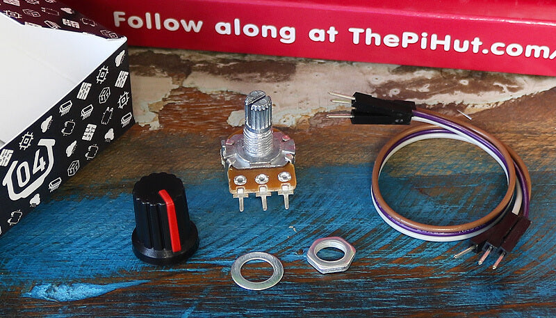
Box #4 Contents
In this box you will find:
- 1x 10k Potentiometer
- 1x Potentiometer knob
- 1x Washer (may be fitted to the potentiometer already)
- 1x Nut (may be fitted to the potentiometer already)
- 3x Male to male jumper wires
Today’s Project
Today we're exploring the wonderful world of analogue.
Until now, we've been using digital signals with the buttons and LEDs in our calendar. Digital signals are strictly a 1 or a 0, HIGH or LOW, ON or OFF. It's one or the other and nothing in between.
Analogue signals offer a wide range of numbers to represent values instead, which is much more suitable for sensors, dials and similar components.
Think of digital as a light switch - it's either on or it's off. Think of analogue as a volume dial on a stereo - you can twist the dial to gradually turn the volume up and down by small amounts.
Our potentiometer can pass these analogue signals (in the form of voltage) to our Raspberry Pi Pico, giving us a gradual input with a wide range of values for us to play with in our code.
What is a Potentiometer?
A potentiometer is a variable resistor.
Our calendar already included traditional resistors for the LEDs, but these were at a fixed value offering a specific amount of resistance. A potentiometer is a resistor that can have its value changed (by turning the knob).
The potentiometer in your box is a 10K potentiometer, meaning it can be set anywhere from 0 ohms to 10,000 ohms (resistance is measured in ohms).
The way we're going to wire our potentiometer allows us to use it to send a varying voltage value to our Raspberry Pi Pico, which some special pins can read, convert and provide a value we can use in our projects.
We're going to explain those pins in a few moments, but for now let's get the circuit built.
Construct the Circuit
Make sure your Pico's USB cable in unplugged before changing the circuit.
Grab your potentiometer, slide the flat washer over the dial and then screw on the included nut (these may already be fitted).
Then, with the potentiometer legs facing downwards, turn the dial all the way to the left and fit the knob with the coloured line pointing bottom-left (like a radio that's turned all the way down).
Leave the LEDs and GND wire (in the blue lane) in place from yesterday's box, but remove the buttons and all other parts. This is our starting point:

Now grab the mini breadboard and fit the potentiometer to the front edge (facing you). Our diagram uses a generic potentiometer image, however as you have a fancy panel mount version, your pins will have a hole space between them:

Next we need to connect the potentiometer to our circuit.
The right pin needs to connect to the 3V3(OUT) pin (physical pin 36), the middle pin to GPIO 27 (physical pin 32) and the left pin to GND (use the blue lane as we already have that connected to GND for the LEDs).

Activity 1: Printing analogue values
Let's start with a simple program that continually prints the analogue reading from our potentiometer.
We're specifically using GPIO27 as this is one of the Pico's ADC pins. But what is an ADC?
ADC Pins
If you look at our Pico pin map again, you'll see that there are three dark green ADC pins available on the right - GPIO26, 27 and 28 (physical pins 31,32 and 34).
An ADC is an Analogue to Digital Converter. The ADC pins on our Pico have the special ability of being able to convert an analogue input into a digital form we can use. We have to import ADC in our code to use this feature.
Note: You'll also spot ADC_VREF and AGND pins, but we're not going to go into those pins in this calendar as we don't strictly need to use those for our example - we'd rather not overcomplicate things whilst we're still learning.
The Code
The code below imports ADC and sets GPIO27 as an ADC pin, then we start a while loop which prints the potentiometer's value every second.
The read_u16 part does this, taking the varying voltage applied to the pin from the potentiometer and scaling this to range of usable output values between 0 and 65535.
(For those who want to get technical - the Pico's ADC pins are 12-bit, however MicroPython scales this to a 16-bit range which is 0-65535).
Run the code below and then try turning the dial - watch the values go up and down as you turn the knob from right to left (the values don't always go right down to zero, this is normal). This is where everything above should start to make sense:
# Imports
from machine import ADC, Pin
import time

# Set up the potentiometer on ADC pin 27
potentiometer = ADC(Pin(27))

while True: # Loop forever

    print(potentiometer.read_u16()) # Read the potentiometer value

    time.sleep(1) # Wait a second
Activity 2: Control LED flashes with analogue values
So, what can we do with this large range of input readings? One thing we can do is use it in our code to control other components, such as our LEDs.
Whereas previously we have turned the LEDs ON or OFF with buttons, the wide range of output readings allows us to tell our code to do different things depending on where abouts it is in the range.
The code below uses the readings to control how fast your LEDs flash. We do this by making a time delay variable.
Variables for Time Delay
We used a variable to make a counter in day #2 which we constantly updated. This time we're using a variable to allow us to set a value in one place rather than having to search through our code for all the various time delays.
For example, let's say that we had 5 LEDs in our code and we use a time delay of 1 second after every flash. From what we've learnt so far, we would use time.sleep(1) after every flash.
That works fine...but it's a bit of a pain to update all of those lines every time we want to adjust the flash speed! Instead we can create a variable and assign it a name such as 'mydelay' and give it a value, say 1.
We can then change our time delay lines to refer to this variable instead of entering a number directly, using time.sleep(mydelay) instead. Now, to update the speed of each flash across our entire program, we only have to update the mydelay variable!
Whilst we only use the delay once in the example below, we thought it was still a nice opportunity to show you another way of using variables to save you time and improve your code.
The Code
The example code below:
- Takes a reading from the potentiometer
- Divides the reading to give us a number that's more usable as a time delay
- Assigns the divided reading to the variable mydelay
- Uses that delay variable to control how long the LEDs are left on and off to create a flashing sequence.
Turn your knob to around half-way to start with, run the code below, then try adding in the other LEDs and making them flash as well, or try adding a print line at the end of the while loop to see what value mydelay is using:
# Imports
from machine import ADC, Pin
import time

# Set up the potentiometer on ADC pin 27
potentiometer = ADC(Pin(27))

# Set up the red LED pin
red = Pin(18, Pin.OUT)

# Create a variable called mydelay and start at 0
mydelay = 0

while True: # Loop forever

    # Update our variable with the reading divided by 65000
    mydelay = potentiometer.read_u16() / 65000

    # Red LED on for the variable delay period
    red.value(1)
    time.sleep(mydelay)

    # Red LED off for the variable delay period
    red.value(0)
    time.sleep(mydelay)
Activity 3: Light LEDs depending on the potentiometer value
We can also use the wide range of analogue values to trigger an action depending on where abouts in the overall range we are. We can do this by using if statements again, this time with conditions that look to see if the value is higher, lower or between a set range!
In our example below, we use a few if statements to check if the reading is less than 20000, between 20000 and 40000, or greater than 40000:
- To make our if statement look for 'less than or equal to', we use a <= operator, like this: if reading <= 20000
- To make our if statement look for a value 'between' two numbers, we use a slightly less-obvious combination of two < operators, like this: if 20000 < reading < 40000
- To make our if statement look for 'greater than or equal to', we use a >= operator, like this: if reading >= 40000
Give it a spin by copying the code below over to Thonny, running it on your Pico and moving the dial left to right slowly. Remember, the code commentary is there to help you understand each line:
# Imports
from machine import ADC, Pin
import time

# Set up the potentiometer on ADC pin 27
potentiometer = ADC(Pin(27))

# Set up the LED pins
red = Pin(18, Pin.OUT)
amber = Pin(19, Pin.OUT)
green = Pin(20, Pin.OUT)

# Create a variable for our reading
reading = 0

while True: # Run forever

    reading = potentiometer.read_u16() # Read the potentiometer value and set this as our reading variable value

    print(reading) # Print the reading

    time.sleep(0.1) # short delay

    if reading <= 20000: # If reading is less than or equal to 20000

        red.value(1) # Red ON
        amber.value(0)
        green.value(0)

    elif 20000 < reading < 40000: # If reading is between 20000 and 40000

        red.value(0)
        amber.value(1) # Amber ON
        green.value(0)

    elif reading >= 40000: # If reading is greater than or equal to 40000

        red.value(0)
        amber.value(0)
        green.value(1) # Green ON
Activity 4: LED Fader using PWM
Now for something a little more advanced, but really cool - we're going to fade an LED in and out using our potentiometer!
To do this we need to use PWM.
What is PWM?
PWM stands for Pulse Width Modulation. It's a type of digital signal where we, over a set period of time, decide how long the signal is ON (HIGH) and how long it's OFF (LOW).
This very fast ON/OFF signal can create a fading effect for LEDs, and can also be used to control robotics components such as servos.
Our code needs some values from us to enable it to run PWM for us - Duty Cycle and Frequency.
What is PWM Duty Cycle?
We can decide how long we keep our LEDs ON/HIGH by changing the Duty Cycle. The duty cycle is the percentage of the time that our LED will be ON. The higher the duty cycle, the longer the LED will be ON, and the brighter our LED will appear.
Duty cycle for the Pico in MicroPython can range from 0 to 65535, which is handy as this matches the output of our potentiometer (0-65535) so we can use this value directly without having to manipulate it.
What is PWM Frequency?
Our PWM code also needs a frequency value, which is the number of times per second that we will repeat the ON/OFF cycle. We use 1000 in the example below.
The Code
So now that we know what PWM, Duty Cycle and PWM Frequency is, let's try it out!
The code example below introduces a few new elements:
- Firstly, we need to import PWM
- We set our LED pin up a little differently to set it as a PWM output, using led = PWM(Pin(18))
- We set the PWM frequency with pwm.freq(1000)
- We create a variable to store the potentiometer reading, and start it at zero using reading = 0
- The while True loop then reads the potentiometer value and stores this in our reading variable, and prints this for us to view in Thonny
- The LED is then given this reading as the duty cycle using led.duty_u16(reading)
- This is followed by a very short delay, then the loop continues
Copy the code below over to Thonny, run it, then turn the dial left to right:
# Imports (including PWM and ADC)
from machine import ADC, Pin, PWM
import time

# Set up the potentiometer on ADC pin 27
potentiometer = ADC(Pin(27))

# Set up the LED pin with PWM
led = PWM(Pin(18))

# Set the PWM Frequency
# Sets how often to switch the power between on and off for the LED
led.freq(1000)

# Create a variable for our reading
reading = 0

while True: # Run forever

    reading = potentiometer.read_u16() # Read the potentiometer value and set this as our reading variable value

    print(reading) # Print the reading

    # Set the LED PWM duty cycle to the potentiometer reading value
    # The duty cycle tells the LED for how long it should be on each time
    led.duty_u16(reading)

    time.sleep(0.001) # Short delay
Day #4 Complete!
Well done makers! We know today was a little heavier as we introduced slightly more advanced topics such as analogue and PWM, so take the time to go back over today's examples and play with the code if you'd like more practice - make it, break it, fix it, learn!
Today you have:
- Learnt about analogue and the difference between analogue and digital signals
- Built a circuit with a potentiometer
- Leant how to use the ADC built into the Raspberry Pi Pico
- Controlled LEDs with an analogue signal
- Learnt about PWM including duty cycle and frequency
Keep your circuit safe somewhere until tomorrow (don't take anything apart just yet). See you then!
We used Fritzing to create the breadboard wiring diagram images for this page.

60 comments
Steve
@Karen, I cannot help but wonder if it’s maybe also the breadboard, sometimes it seems quite loose when connecting the jumper wires with the male DuPont connectors. I also think it’s possible to push components in too much, I did that with the LEDs and I think I ended up making it worse on those columns of 5 points in the main part.
I did try and stick to just the wires provided but I’ve played around with electronics before and had this type of issue with breadboards from other companies. I’ve also got what PiHut sell as Jumper Wire Kit, the solid core wires of different cut sizes with bare ends to plug into the breadboard. They do a really nice job of connecting the long power rails to holes in the main section for the power pins on the pico, I swapped to that for a power yesterday on day 4 but am still using the wires provided for the rest. Maybe the small jumper wires do better just because they are flat to the breadboard and don’t have the longer wire sticking up in the air that can be pulled about.
I got the same sort of thing you did with the potentiometer readings at first, I think I just disconnected and re-connected. unplug and plug in again, a lot like working with computers and microcontrollers, turn it off and on again :).
Hopefully you have better look in the coming days.
The Pi Hut
@Andie – These tutorials will stay online forever, so they will always be here to come back to if needed :)
@Andie – These tutorials will stay online forever, so they will always be here to come back to if needed :)
Andie
At the end of day 12 are you going to release the instructions as a download to keep?
At the end of day 12 are you going to release the instructions as a download to keep?
The Pi Hut
@Karen – You might be having a similar problem to another customer who got in touch. They provided a picture of their setup and we saw that they hadn’t pushed the Pico completely into the breadboard. If correctly fitted, the black plastic strips should be flush against the breadboard and none of the metal legs should be visible. If that doesn’t help, please get in touch via support.thepihut.com and we’ll help.
@Karen – You might be having a similar problem to another customer who got in touch. They provided a picture of their setup and we saw that they hadn’t pushed the Pico completely into the breadboard. If correctly fitted, the black plastic strips should be flush against the breadboard and none of the metal legs should be visible. If that doesn’t help, please get in touch via support.thepihut.com and we’ll help.
giles
Thanks for continuing with the high quality tutorials. I’m really looking forward to finding out what else is coming in the remaining days!
I’ve made a binary counter controller that makes use of both the pot and the buttons for control. It demonstrates some more MicroPython features like classes and threads.
My source is here for anyone who is interested: https://github.com/gilesknap/pico-xmas#day-4-project
Karen Hobson
Although my son is really enjoying this, we’re a bit disappointed (and frustrated) with how unreliable the connections seem to be and his has so far affected our success every day. The main issue seems to be because the breadboard isn’t flat and the chip doesn’t reliably make connection on every pin (we have to regularly push it back down). Examples: Day one – only two out of the three LEDS would light. Today, we were initially only getting readings between zero and 600, it was only when we pushed the chip down again we were getting the sort of numbers the program suggested.
Although my son is really enjoying this, we’re a bit disappointed (and frustrated) with how unreliable the connections seem to be and his has so far affected our success every day. The main issue seems to be because the breadboard isn’t flat and the chip doesn’t reliably make connection on every pin (we have to regularly push it back down). Examples: Day one – only two out of the three LEDS would light. Today, we were initially only getting readings between zero and 600, it was only when we pushed the chip down again we were getting the sort of numbers the program suggested.
Steve
@David, I agree, it’s a nice way to spend a bit of time each day.
Big thanks to PiHut for offering this produce and including the great guides and it’s been clear they have people keeping an eye out on the comments to help people when needed (and so far it seems responding really quickly) which is good to see.
jonathon simons
I have really enjoyed the projects so far. I have learnt so much I am looking forward to combining what I have learnt to create my own projects
I have really enjoyed the projects so far. I have learnt so much I am looking forward to combining what I have learnt to create my own projects
David
Just wanted to add to the folks giving positive feedback on this kit and the excellent accompanying tutorials. I’m an experienced tinkerer, and have been using and coding Picos since day one, usually in C but I’m really enjoying going back to basics with this, and playing with things as if it was for the first time. The kit is so well thought out and put together, and the documentation is just first rate. Loving it.
Just wanted to add to the folks giving positive feedback on this kit and the excellent accompanying tutorials. I’m an experienced tinkerer, and have been using and coding Picos since day one, usually in C but I’m really enjoying going back to basics with this, and playing with things as if it was for the first time. The kit is so well thought out and put together, and the documentation is just first rate. Loving it.
Estelle
Enjoying making the projects from the calendar! I found that my potentiometer never output a 0 value so when I did activity 4 the LED didn’t fade up from an off position. If it helps anyone else, I adapted the second to last line of code to make the LED start from an off position when fading up:
if reading < 1000:
led.duty_u16(0)
else:
led.duty_u16(reading)