

Let it Glow Maker Advent Calendar Day #3: Incredible Inputs!
It’s day #3 of the Let it Glow Maker Advent Calendar!
Yesterday we got familiar with creating circuits with outputs (using our LED) and using that circuit with code. Today we're going to look at inputs and how they can trigger our code to do different things.
There's no better way to introduce you to inputs than by using a button, and this year's calendar includes two chunky coloured buttons which are easy to use and add some zing to our breadboard! Using buttons in conjunction with LEDs and other blinky bits is a great way to make a fun, interactive project!
We're going to make our button control our LED using code, so we're already starting to make our components work together...and it'll just get better every day!
Let’s do it!
Box #3 Contents
In this box you will find:
- 1x Green 12mm Square Tactile Button
- 1x Red 12mm Square Tactile Button
- 5x Male to male jumper wires

Today’s Activities
Today we’re going to learn how to use buttons in a circuit to trigger things in our code, such as printing text, lighting our LED and counting numbers.
We'll be introducing some new skills and functions that will come in handy as we progress though the calendar.
Those of you who completed our 12 days of Codemas Calendar last year will be familiar with buttons as they’re the most popular option for sending inputs to a microcontroller. This is why we’ve included a different colourful style of button this year, but as we've now covered the basics, the similarities between the two calendars pretty much ends here!
How does a button work?
We all know what a button is - most of us use them every day - however some might be wondering what makes them work and what's going on underneath that colourful cover?
Buttons simply give us an easy way to make or break a circuit. It's the same as connecting or disconnecting a wire, just in a format that makes it easy for us!
The difference with microcontrollers is that the circuit can be used to send a signal (an input) whenever the button is pushed, which can then tell our code to do something. When we push a button in the circuit we're about to make, electrical signal (3.3V) is allowed to continue its way forward to our GPIO pin, which the pin can detect and make the code react to as a result.
Construct the Circuit
As always, make sure your Pico is disconnected from the USB cable when working on the circuit.
Prepare the breadboard
You should have the LED from yesterday's box still in place. If not, head on back to day #2 and re-build that circuit.
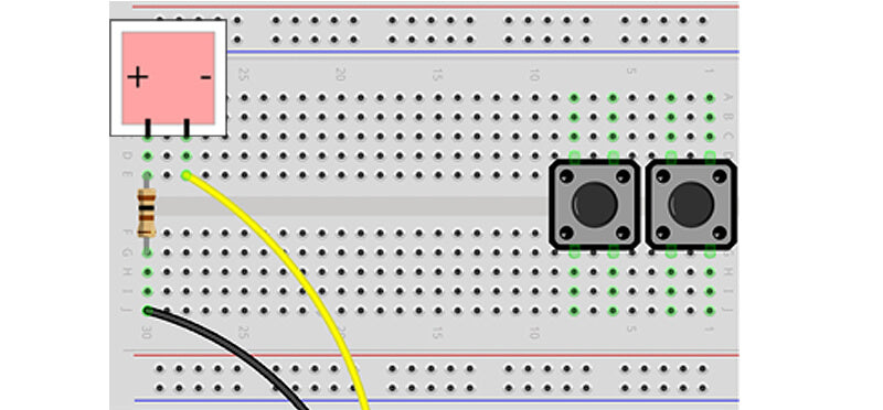
Fit the buttons
First we need to pop those big juicy buttons into our breadboard. Take a look at the image below and fit them into the same positions, taking note of the lanes that the legs sit in. Once you're happy the legs are in the right places and not bent, give the button a firm push and you should feel it slot in nicely.
If it feels loose, pops out or the black base of the button isn't touching the breadboard, you've not been firm enough or the legs are bent and need correcting.
The buttons straddle the central break in the breadboard which stops the two sets of legs touching together and shorting our circuit.
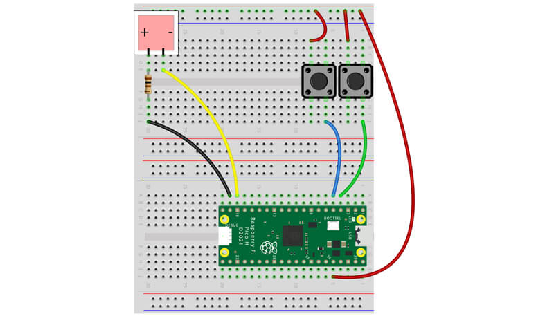
Next we need to hook the buttons up to our Pico's GPIO pins.
We're first going to create a 3.3V power rail using one of the red lanes, which we can then tap in to. There's only one 3.3V pin on the Pico, so this allows us to make multiple connections to it.
Connect a jumper wire from the 3V3 OUT pin (physical pin 36), then fit the other end into the top red rail. Now that the entire rail is connected to the 3.3V pin, we can connect both of our buttons to it. Connect the top-left leg of each button to that rail using a jumper wire for each, like this:

Finally we need to connect the other side of our buttons to GPIO pins.
Connect the left button's lower-right leg to GPIO3 (physical pin 5), and the right button's lower-right leg to GPIO2 (physical pin 4), like this:
A few tips & pointers
- If the jumper wires feel like they don't want to go in, just give them a little twist. Sometimes they just get caught on something and rotating them slightly helps that.
- Once you start running code, if you find that the button is constantly detected as being pressed, it's likely that you've hooked a wire up to the wrong leg, making the connection constant.
- If you find a button just won't stay put and keeps popping out, try moving the jumper wire to as different hole in the same lane, or try fitting the button in a different position further along the breadboard.
Buttons at the ready - let's code!
Activity 1: Basic button usage
We'll cover the basics of using buttons with MicroPython/the Pico first, then move on to slightly more advanced projects.
We're going to re-use some of the things we used yesterday, mostly while loops. Loops are commonly used for buttons and inputs as they can be used to continually check the status of an input to see if it has changed.
Inside our while loop we'll use something new - an if statement - to determine what happens when a button is pressed.
If Statements
If you've used Microsoft Excel or similar software previously, you'll have already guessed what if statements do.
If statements allow us to give our code different outcomes depending on values, inputs and many other things, such as "if the first button is pressed, light the LED" . If the condition for the statement is met, our program will run the code inside the code block which is indented underneath.
Indentation is important here - the while loop block is indented, but as the while loop contains an if statement, we indent yet again for the if statement block of code. Look at the example below to see this in action.
If statements can be very powerful and there are lots of different and advanced ways to use them. You'll use them lots when making your own projects. We'll start with a nice simple example, but first let's explain something else new in our code - pull downs.
Pull downs
Our code below also uses pull downs - you can see this at the end of each of the button set up lines as Pin.PULL_DOWN.
So why do we add this? When we use a button, we're sending 3.3V to the GPIO pin to set it HIGH, however we need to make sure the pin is LOW in the first place or our code might not be able to detect the change and/or it might trigger itself randomly.
This is because GPIO pins with no pull down (or pull up) can be 'floating' between 0V and 3.3V - 'pulling down' the pin to 0V ensures it's always LOW to start with.
Sometimes this is achieved by using physical resistors in a circuit, however some microcontrollers (such as our Pico) have this functionality built-in and we can simply enable them in our code. Handy!
The Code
We'll just use one of our buttons to start with, the red one (the right button).
The code includes our usual imports and then sets up the button pin. This is set as an input (Pin.IN) with the pull down (Pin.PULL_DOWN)).
The code then starts a while True loop. The while loop contains an if statement that looks for a HIGH signal (1) on GPIO 2.
If the button is pressed and a signal is sent to that pin, our code will print "Red button pressed".
We include a short delay in this loop to give your finger a chance to release the button, to avoid the code triggering many times from a single press (known as debouncing). Values of 0.1 or 0.2 seconds usually work well.
Copy the example over to Thonny and give it a go:
# Imports
from machine import Pin
import time

# Set up our button name and GPIO pin number
# Set the pin as an input and use a pull down
redbutton = Pin(2, Pin.IN, Pin.PULL_DOWN)

while True: # Loop forever

    time.sleep(0.2) # Short delay

    if redbutton.value() == 1: #If the red button is pressed
        print("Red button pressed")
Easy right? Let's move on and add our other button in.
Activity 2: Multiple button inputs
Just like when we added additional LEDs to our code in yesterday's box, we'll be adding your second (green) button to the script, and altering the code to do something different depending on which button is pressed.
The first part is adding the pin set up line. Just duplicate that line and call it something different, we went with the obvious 'greenbutton'. Change the GPIO number to 3 as well, as our green button is connected to that pin.
Then all we need to do is add a second if statement to tell our program what to do if a different input is detected, changing the button it's looking for, and the text to print.
Take a look at the code example below and give it a try yourself:
# Imports
from machine import Pin
import time

# Set up our button name and GPIO pin number
# Set the pin as an input and use a pull down
redbutton = Pin(2, Pin.IN, Pin.PULL_DOWN)
greenbutton = Pin(3, Pin.IN, Pin.PULL_DOWN)

while True: # Loop forever

    time.sleep(0.2) # Short delay

    if redbutton.value() == 1: #If the red button is pressed
        print("Red button pressed")

    if greenbutton.value() == 1: #If the green button is pressed
        print("Green button pressed")
Activity 3: LED Control with buttons
Before we go any further with inputs, let's bring our LED back to the party and control it with our inputs. We'll make our green button turn the LED on, and the red one turn it off.
To do this, we first need to add back in the LED pin setup code from yesterday's box. You'll see this under the button set up lines in the example below.
Then under each if statement we'll add the LED code after the print line. You can add as much code as you like within if statements, which makes them really handy when you want a condition to trigger a whole range of events and devices.
Copy the example below over to Thonny and give it a try:
# Imports
from machine import Pin
import time

# Set up input pins
redbutton = Pin(2, Pin.IN, Pin.PULL_DOWN)
greenbutton = Pin(3, Pin.IN, Pin.PULL_DOWN)

# Set up output pins
redled = Pin(14, Pin.OUT)

while True:

    time.sleep(0.2)

    if redbutton.value() == 1:
        print("Light OFF")
        redled.value(0) # LED pin LOW

    if greenbutton.value() == 1:
        print("Light ON")
        redled.value(1) # LED pin HIGH
Activity 4: Toggling LEDs with buttons
Using our buttons to turn the LED on and off is handy, but in reality most the devices in our homes use a single button to toggle them on/off.
What if there was a better way...
Toggle function
...there is! The toggle function does exactly what you'd expect - it toggles the state of a pin between HIGH and LOW, meaning you can use a single button as a light switch or similar.
It also reduces the amount of code required, which is always a good thing when working with microcontrollers with limited storage.
We simply use redled.toggle() instead of the usual line turning the LED on or off. Easy! Try the code below to see it in action with your red (right) button:
# Imports
from machine import Pin
import time

# Set up input pins
redbutton = Pin(2, Pin.IN, Pin.PULL_DOWN)

# Set up output pins
redled = Pin(14, Pin.OUT)

while True:

    time.sleep(0.2)

    if redbutton.value() == 1:
        redled.toggle()
Activity 5: Counting with buttons
We can make our program count and manipulate numbers, using the buttons to add or subtract from a stored value. This comes in handy when creating little games or setting things like volume, brightness and other things that have a range of values.
This stored value is called a variable. Let's quickly cover variables before we continue...
Variables
A variable is just somewhere to store a value (a 'container'), which we can also update when we want to. When we need to use the variable in a line of code, we just use its name.
In our example below our variable is called count. We create this before the while loop and set an initial value of 0.
In programming, a variable can be a whole number (an 'integer'), a number with a decimal place (a 'floating-point value' or 'float') or a word/text (a 'string'). We'll be using an integer here.
The Code
The code below first imports the things we need, sets our pin numbers up, then creates a variable called ‘count’ which we’ll use to track presses on our buttons as part of the while loop.
The red button will reduce the count by 1, and the green button will increase it by 1 (feel free to swap them around if you prefer - you have the skills to do that now!).
# Imports
from machine import Pin
import time

# Set up input pins
redbutton = Pin(2, Pin.IN, Pin.PULL_DOWN)
greenbutton = Pin(3, Pin.IN, Pin.PULL_DOWN)

# Set up counter variable
count = 0 # Start at zero

while True:

    time.sleep(0.2)

    if redbutton.value() == 1:
        count = count -1 #Reduce count by 1
        print(count) #Print our updated count

    if greenbutton.value() == 1:
        count = count +1 #Increase count by 1
        print(count) #Print our updated count
Activity 6: Counting with buttons (blinky version)
We're going to make our LED flash each time one of our buttons are pressed, just for a bit of visual feedback and a way to show you yet another way to utilise LEDs in your projects.
It's mostly the same code, just with LED control elements added back in. We turn the LED on within each if statement (after we've pressed the button), but it's turned off again as the code cycles back into the loop, where we turn it off after the short 0.2-second delay.
This creates the effect of a flash every time a button is pressed. Give it a spin:
# Imports
from machine import Pin
import time

# Set up input pins
redbutton = Pin(2, Pin.IN, Pin.PULL_DOWN)
greenbutton = Pin(3, Pin.IN, Pin.PULL_DOWN)

# Set up output pins
redled = Pin(14, Pin.OUT)

# Set up counter variable
count = 0

while True:

    time.sleep(0.2)

    redled.value(0) # LED off until button press

    if redbutton.value() == 1:
        count = count -1
        redled.value(1) # LED on
        print(count)

    if greenbutton.value() == 1:
        count = count +1
        redled.value(1) # LED on
        print(count)
Day #3 Complete!
Another decent day of learning folks - we've got a good handle on inputs, loops and if statements now, which is going to come in really handy for the fun stuff coming up in the next boxes.
We covered the most basic use of if statements today, however we'll be returning to them to show you more advanced things we can do with them.
Recap time – what did we cover in today’s box?
- Wiring a button circuit
- How to use inputs with MicroPython
- Basic If statement usage
- Pull downs
- Controlling an output with an input
- The toggle function
- Variables
- Integers, floats and strings
- Counting with variables
Keep your breadboards safe somewhere and leave the circuit as it is - we'll be using some of it again tomorrow. See you in the morning!
We used Fritzing to create the breadboard wiring diagram images for this page.

25 comments
Micha
Hello PiHut team, I bought one of your calendars for the first time. So far, I only have very rudimentary knowledge of Python. But with your excellent instructions, I am understanding more and more. (By the way, I fell into the same trap as James :-) )
Hello PiHut team, I bought one of your calendars for the first time. So far, I only have very rudimentary knowledge of Python. But with your excellent instructions, I am understanding more and more. (By the way, I fell into the same trap as James :-) )
Srishty
This is so fun!
This is so fun!
The Pi Hut
@David – We love that you love it 😊🎄
@James – We recommend more coffee and chocolate ☕ It’s an easy trap that one – physical pin numbers vs GPIO numbers has always tripped people up, especially with the Raspberry Pi.
@David – We love that you love it 😊🎄
@James – We recommend more coffee and chocolate ☕ It’s an easy trap that one – physical pin numbers vs GPIO numbers has always tripped people up, especially with the Raspberry Pi.
James
Urgh, I HATE brainfog … it’s just taken me an hour of fiddling and a walk to clear the red mist to realise that the Pin# in the code is the GPIO ID and that the physical pins have different numbers … le sigh.
I don’t suppose you also sell working brains?
Urgh, I HATE brainfog … it’s just taken me an hour of fiddling and a walk to clear the red mist to realise that the Pin# in the code is the GPIO ID and that the physical pins have different numbers … le sigh.
I don’t suppose you also sell working brains?
David McCall
I absolutely love this advent calendar
I absolutely love this advent calendar
The Pi Hut
@Lyam @harry – Sorry to hear that folks ☹️ Please get in touch with our support team via support.thepihut.com and they will send replacements to you ASAP.
@Lyam @harry – Sorry to hear that folks ☹️ Please get in touch with our support team via support.thepihut.com and they will send replacements to you ASAP.
harry
I have the same problem as Pavol
I have the same problem as Pavol
Lyam
Hello,
One of the feet on one of the buttons has snapped off, is it possible to reorder one?
Thanks for your help,
Lyam
Hello,
One of the feet on one of the buttons has snapped off, is it possible to reorder one?
Thanks for your help,
Lyam
The Pi Hut
@Simon – It’s a common problem (perhaps so common that it’s now just seen as normal!). The internal metal parts can become misaligned, sometimes just a row can be fiddly, or an entire section. Our best advice is to use something with lots of fixed legs (like a Pico) to push in and realign things. Or if you’re having trouble getting a single jumper wire pin to push in, try rotating it a little and you’ll find they just fall into place.
@Simon – It’s a common problem (perhaps so common that it’s now just seen as normal!). The internal metal parts can become misaligned, sometimes just a row can be fiddly, or an entire section. Our best advice is to use something with lots of fixed legs (like a Pico) to push in and realign things. Or if you’re having trouble getting a single jumper wire pin to push in, try rotating it a little and you’ll find they just fall into place.
Simon
I have an issue with one of the breadboards – some of the holes are easy to insert jumpers and others devices into; some of them are really difficult (and I can’t seem to push them in no matter how hard I try).
The other breadboard seems fine – luckily that’s the one that I put the Pico H into!
I have an issue with one of the breadboards – some of the holes are easy to insert jumpers and others devices into; some of them are really difficult (and I can’t seem to push them in no matter how hard I try).
The other breadboard seems fine – luckily that’s the one that I put the Pico H into!
Sam
Loving the calendar so far. The daily guides are very well written.
Loving the calendar so far. The daily guides are very well written.
The Pi Hut
@Pavol – Sorry to hear that, please get in touch via support.thepihut.com and we’ll help with a replacement.
@Pavol – Sorry to hear that, please get in touch via support.thepihut.com and we’ll help with a replacement.
Pavol
My block LED only lasted on day 2, on day 3, after i added the buttons it stopped working. Poor quality i have to say ! Had to replace with plain LED to carry on with buttons on day 3.
My block LED only lasted on day 2, on day 3, after i added the buttons it stopped working. Poor quality i have to say ! Had to replace with plain LED to carry on with buttons on day 3.
The Pi Hut
@D.C. – Yes the jumper wires can be separated, they’re designed to be pulled apart and used individually where needed.
@D.C. – Yes the jumper wires can be separated, they’re designed to be pulled apart and used individually where needed.
D.C.
Are we supposed to separate the 5 wires?
Are we supposed to separate the 5 wires?
The Pi Hut
@James – Yes you end up with lots of spares as almost every day we give you more, so you should be fine. Jumper wires don’t last forever (they’re almost a consumable!) but sometimes you’ll get a few that fail a little earlier than expected :(
@James – Yes you end up with lots of spares as almost every day we give you more, so you should be fine. Jumper wires don’t last forever (they’re almost a consumable!) but sometimes you’ll get a few that fail a little earlier than expected :(
The Pi Hut
@Giles – Looks great, an excellent additional resource. Thanks!
@Giles – Looks great, an excellent additional resource. Thanks!
James
I’m really enjoying the calendar but…Are there any spare jumper wires in the set? One of mine snapped when I brushed against it just before I tested the first code today (I’m spreading mine over the full 24 days)! I’m quite keen to avoid calendar spoilers, but would be helpful if there was a box I could quickly pluck one from.
I’m really enjoying the calendar but…Are there any spare jumper wires in the set? One of mine snapped when I brushed against it just before I tested the first code today (I’m spreading mine over the full 24 days)! I’m quite keen to avoid calendar spoilers, but would be helpful if there was a box I could quickly pluck one from.
Giles
For some advanced Micropython using today’s additional hardware see https://github.com/gilesknap/pico-xmas/blob/main/README2023.md
I’m using interrupts and asyncio to continuously monitor both button states and blink the LEDs.
- Red button toggles between blinking and always on
- Green button toggles between on and off
The code is split into modules and classes so you can re-use the button monitoring bits if you so please.
CHRISTOPHER PARKER-JONES
Great kit glad I bought it can’t wait for tomorrow to come :-)
Great kit glad I bought it can’t wait for tomorrow to come :-)
The Pi Hut
@Bill Pitwood – That is just awesome! It’s so nice to hear that our calendar is bringing you back into coding. More fun is on the way!
@Bill Pitwood – That is just awesome! It’s so nice to hear that our calendar is bringing you back into coding. More fun is on the way!
The Pi Hut
@Mike – You’re absolutely correct – for each example you copy over, you need to clear the old one (we use Ctrl+A to select the entire script, then hit delete). We’ll add this to this evening’s edits as it would be useful to make this clear to everyone taking part.
@Mike – You’re absolutely correct – for each example you copy over, you need to clear the old one (we use Ctrl+A to select the entire script, then hit delete). We’ll add this to this evening’s edits as it would be useful to make this clear to everyone taking part.
rob
Great fun
Great fun
Bill Pitwood
Haven’t done any programming since the mid-80s on a Sinclair Spectrum and always wanted to get back into it….
So, here I am, a few weeks short of my 69th birthday learning new tricks.
Finding it very easy to follow, well explained and really feeding my creative side. Can’t wait for each day to see what comes next. Thanks guys… Let it Glow !!
Mike
Did I miss something.?
The instructions don’t make it clear you need to clear the code you have written for the previous exercise. Maybe you don’t, but it is the only way I could make it work.
Mike
Did I miss something.?
The instructions don’t make it clear you need to clear the code you have written for the previous exercise. Maybe you don’t, but it is the only way I could make it work.
Mike