How to assemble HotPi
The HotPi is a Raspberry Pi add-on board created by Karl Lattimer and originally promoted through a successful Kickstarter project. It is a multi-function board with some unique functions that I don’t think I have seen on any other board.
-
Infra-Red Remote Control Transmitter and Receiver enabling you to control the Raspberry Pi with any IrDA remote control, like the one for your TV, and also to control other devices that have IrDA receivers, like your TV.
-
A Full Colour Range RGB LED, which is a Light Emitting Diode that you can control the colour of. You can use this, for example, to provide coloured notifications through the Raspberry Pi.
-
A Battery Backed Real Time Clock to keep the time accurate when the Raspberry Pi is turned off or disconnected from a network.
-
A Speed Controlled Fan Connector that can be controlled by the Raspberry Pi.
The Kit
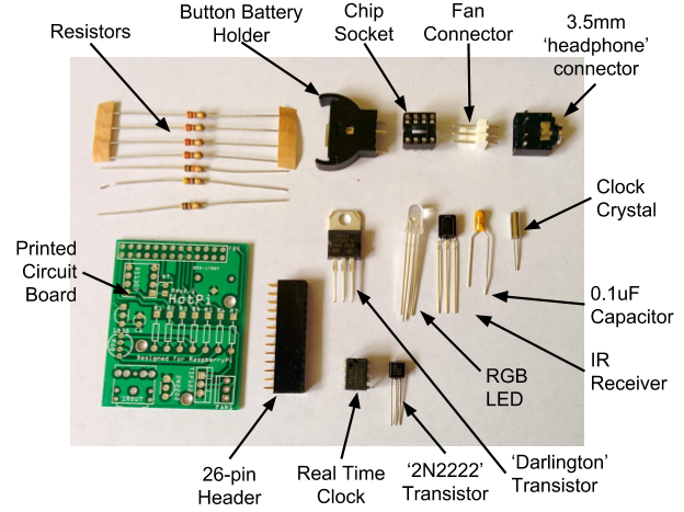
The HotPi comes as a kit, consisting of a printed circuit board (PCB) and a number of components that you must solder onto the board. Don’t worry if you have never soldered before! If you own a Raspberry Pi then it is a skill that you should master to get the most fun out of the little computer.
So, what is in the kit?
And what does each bit do?
There are probably a few bits in this kit that are new to you. Lets go through each one so that you know what they are for before we go through the process of assembling the kit.
The Printed Circuit Board
Printed circuit boards (or PCBs) are made from lots of different layers that form the connections between the various components that are soldered to it. Each PCB is designed for a specific purpose. For this kit, the side with all the writing is the ‘top’ side, where all the components will be. The majority of the soldering will be done on the ‘bottom’ side that will remain out of sight once connected to the Pi - so don’t worry what your soldering looks like!
Resistors
Resistors are used in a circuit to reduce the current (Amps) that is allowed to go through a circuit. The bigger the resistance, the harder it is for the current to pass. This kit contains seven resistors with four different values. Their position on the PCB is marked with the letters R1 through to R7.
The value of a resistor is shown as a number of coloured bands across the body of the resistor. The ones with this kit all have four bands, ending in ‘gold’. I’m not going to explain how to read all resistors here, as there are lots of other places on the internet that you can read up about them.
The resistors in this kit are:
|
PCB Identity |
Resistance Value |
Colour Bands |
|
R1 |
100Ω |
Brown, Black, Brown (Gold) |
|
R2 |
47Ω |
Yellow, Violet, Black (Gold) |
|
R3 |
10kΩ (10,000 Ω) |
Brown, Black, Orange (Gold) |
|
R4, R5, R6, R7 |
200Ω |
Red, Red, Brown (Gold) |

26-pin Header
The 26-pin header is the part that plugs onto the Raspberry Pi’s 26 pins. This is the only part that mounts on the bottom of the PCB, with the pins poking through to the top and the soldering done from the top.

Capacitor
Capacitors store and release energy in a controlled fashion. There are a few types of capacitor and some have a positive and negative end, and some don’t. The 0.1uF capacitor in this circuit has a negative and a positive leg. The positive leg is the longer of the two legs. The negative leg is the shorter one, and goes into the hole on the PCB that is marked with two small ‘-’ signs.
Unfortunately, you don’t have a flux capacitor in this kit, so taking it to 88mph will not allow you to travel in time.
IR Receiver
The infrared receiver converts the infrared signal from your controller into electrical pulses that are interpreted by the Raspberry Pi. It has three legs. The front is rounded, and the back is flat. When you solder it onto the PCB the round side should be pointing outwards.

RGB LED
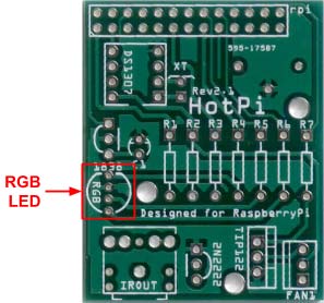
The RBG LED is an Light Emitting Diode that can display almost any colour. It has four legs - one for each of the colours Red, Green and Blue, and one for the ‘common cathode’. Each leg has a different length, and you must make sure that you get them in the right holes. You either use the length of the legs to identify which one should go where, or one side of the lamp has a flat side. On the PCB you will see that there is a flat side to the circle surrounding the holes for the LED. The diagram below (from the components data sheet) shows which leg is which, and that the ‘flat’ side of the LED is the one next to the red leg.

Transistor
Transistors are used either as a signal amplifier, meaning that an input voltage is made larger on the output leg, or as a switch. The resistor used in this circuit has three legs. The body has a flat side, which helps identify which way round it goes on the PCB. You should match the flat side of the transistor to the flat edge of the drawing on the PCB
.
‘Darlington’ Transistor
The larger ‘Darlington’ transistor is actually two transistors in one package, giving a much larger amplification to the input signal. Once again it has three legs, but it also has a large metal backplate with a hole in it. This acts as a cooling surface as it can get very hot depending on its use. Sometimes a heatsink is screwed onto the backplate via the provided hole, but in this case it is not required.
The orientation of the transistor is shown on the PCB by the thinner area marked with two small lines - indicating the hole in the backplate. This is showing the backplate towards the fan connector and the front of the transistor towards the other transistor.
Molex 3-Pin Fan Connector
The fan connector is a connector designed by the Molex company that has become the standard for many computer components. This connector allows you to connect a 5 volt variable speed fan (not supplied) to the board. The board, however, does not currently support the reading of the actual speed of the fan.

If you look at the connector you will see a plastic back sticking up. This should be facing the Darlington transistor.
Real Time Clock
The Real Time Clock is the chip that keeps track of time when the Raspberry Pi is switched off or when it’s not getting the latest time from the Network Time Protocol clocks on the internet. This chip is powered by the battery when the Raspberry Pi is not supplying the power, but takes so little power that the battery should last for a very long time (many months or years).

We’re not going to solder the chip directly to the PCB, although it is possible to do so. Instead we’re going to use a chip holder. Chips can be quite delicate, so the use of this holder will help save any accidental mishaps.
On the PCB you will see a rectangle with a bit missing from one end. This bit corresponds to a ‘notch’ on the chip holder as well as a notch on the chip itself. Make sure the holder is soldered onto the PCB with the notch over this missing line.
Crystal Resonator
The Crystal Resonator is the tiny cylindrical component with very thin wires coming out of it. This supplies the clock signal to the real time clock. It does not matter which way round this goes.
‘Stereo Headphone’ Connector
Does this board supply sound? No, it doesn’t. what this connector is here for is to accept one of the many IR Transmitters that you can buy which uses the same sized connector as your headphones. Do not try and connect your headphones into here, though, as you may damage either the headphones, the HotPi, or both
.
The arrangement of the pins on the connector means that this can only go round one way.
Battery Holder
The last part of the kit is the coin battery holder. The CR2032 battery is not supplied due to some export restrictions and safety. However, you can easily pick up coin battery cells from eBay for very little. This is another component whose legs will only allow it to be soldered to the PCB one way round
.
Putting it All Together
Now that you understand what is in the kit, where it goes and which way round everything goes, it’s now down to you putting it all together.
As well as this kit, you will also need:
-
(Not Optional) A Soldering Iron - You don’t need to invest in an expensive one at first; indeed my latest one cost me just £9 and that is with variable temperature, but I prefer to use my old 15W iron due to the small tip. As long as the one you get has a pointed tip and not the spade tip, then you should be okay. The soldering iron from The Pi Hut is ideal (http://thepihut.com/products/antex-xs25-soldering-iron-uk-plug)

-
(Not Optional) Lead-Free Solder - You can get both leaded and lead free solder. The latter is advised as the lead vapourises as it is heated and is poisonous, although it does melt at a lower temperature. The Pi Hut sells exactly what you need (http://thepihut.com/products/antex-lead-free-solder).

-
(Not Optional) Wire Cutters - to trim the ends of the components once soldered in place. A nice precision set like the ones at Pi Hut are ideal (http://thepihut.com/products/high-precision-diagonal-micro-cutters).

-
(Optional) Soldering Iron Stand - To stand the soldering iron on while it’s heating up and while you are placing parts. It also keeps the hot end out of the way. They are not that expensive and do help out, so why not get one when you buy your soldering iron (http://thepihut.com/products/antex-bench-stand)?

-
(Optional) A Solder Sucker and/or Desoldering Wick - to remove solder if you accidentally make a mistake. And you will! (http://thepihut.com/products/aluminum-solder-sucker or http://thepihut.com/products/desoldering-wick)


-
(Optional) Soldering Vice - To hold a circuit board while you solder parts. Not an absolute must for this kit; I didn’t use one, although I have for other kits I have built. (http://thepihut.com/products/third-hand-soldering-stand-with-magnifying-glass)

-
(Not Optional) Blu Tack or Similar - Your best friend! Holds everything in place while you solder. Most experienced kit-builders will have this in their toolbox (http://thepihut.com/products/blu-tack-handy-pack).

Soldering Order
I’m not going to attempt to teach you how to solder in this section - there are whole books on the subject from all good local bookshops as well as Amazon . There are a few things that I am going to say or remind you of, though:
-
Do not melt the solder onto the parts you are soldering - you need to heat up the two surfaces that need soldering together for a few seconds, and then put the solder onto those surfaces. The solder will melt on both surfaces, making a good connection.
-
Don’t use too much solder. Too much solder will most likely make short circuits between components.
-
If a joint doesn’t take, just heat it up again with the solder that is already there and it will reflow into the joint. This is often enough to make the joint good again.
-
Don’t touch the hot end of the soldering iron. Ouchy ouchy may result.
-
Don’t give up if the first few joints don’t look good or work well. As with many things, it takes practice, and you will get better with time.
-
Always double-check that the component is round the right way before soldering. There is nothing more annoying than getting a perfect joint, trimming the legs off, only to discover that the part is round the wrong way.
-
But if you do do that, it is not a disaster. Just unsolder and try again.
-
Blu Tack is your new best friend! It holds things in place and stops the PCB from wandering around your desk while you are soldering.
There is no ‘proper’ order in which the components must be soldered into place, although experience may give you a preferred order. The original instructions for this kit suggest soldering the crystal resonator first, but that’s the last part that I would do. The legs are so thin that there is a chance that they could get broken as you move the board about.
Resistors
Instead I would start with the easiest parts - the resistors. Make sure you know which resistor is which by looking at the colours. Use a good light and a magnifying glass if needed. Please them one by one into their respective holes and once through, bend the legs out slightly to hold them in place. Try and make all the resistors line up and the colours all pointing in the same direction; this is not for functionality, but it just makes the board look neat.
Here is a reminder of which resistor goes into which location on the PCB:
|
PCB Identity |
Resistance Value |
Colour Bands |
|
R1 |
100Ω |
Brown, Black, Brown (Gold) |
|
R2 |
47Ω |
Yellow, Violet, Black (Gold) |
|
R3 |
10kΩ (10,000 Ω) |
Brown, Black, Orange (Gold) |
|
R4, R5, R6, R7 |
200Ω |
Red, Red, Brown (Gold) |
Once you have soldered all the resistors, turn the board over and check that they are all in place. Sometimes they are raised above the board and look a little untidy. This is easy to fix, although be careful not to burn yourself with the next steps.
Ensuring the board is held down (with a little Blu tack) re-heat the solder on the end of the resistor that is raised a little while either pulling the leg that needs to move with pliers. As the solder melts the resistor will move into place.
Once you are happy with the positioning of the resistors and you have checked that they are all in the right place, trim off all the excess wire down to the top of the solder.


Passive Components
Next, I suggest some of the passive components. By passive I mean the ones that just have current going through them and do not act on that current. These are the sockets: the chip holder, the 3.5mm ‘headphone’ socket, and the fan connector. I’m going to leave the battery holder until later as it’s large and will make it a little harder to hold the other components in place while you solder.

26-Pin Connector
Now turn the PCB over and place the 26-pin connector in place. This is the only component that sits under the board, and is soldered on top of the board.

Fix it in place with Blu tack and solder one of the middle pins. Remove the Blu tack and check that the connector is straight and flush with the PCB. If not, then heat the solder while pushing the connector into place.
Once you are happy with placement, solder all the rest of the pins.
Active Components
Now we’re going to solder the active parts onto the board, starting with the transistor, capacitor, IR receiver, LED then Darlington Transistor. Do each of these one at a time. Don’t rush and try to do two or three - it doesn’t save time in the long run.
Remember to check and double check that you have the components round the right way each time, both before and after soldering. Once these checks have been done you are then free to cut the protruding wire off.
The LED is unlikely to be completely flush with the PCB. This is fine, and is due to the PCB hole spacing being different to the LED itself.
The Darlington Transistor will stand proud of the PCB - there will be a few millimetres of leg on the topside of the PCB. This is expected and is normal.
Last Parts
The last but one soldering in this kit that I would do is the small clock crystal, finishing with the tallest component, the battery holder.
For the battery holder, solder the middle leg first then check that it is perpendicular to the PCB. Then solder the other two joints.
Check Again
Before you plug in the clock chip (first) and battery (second), check everything once again. If you’re happy with the soldering, insert the chip first, remembering to line up the notches, and then insert the battery ensuring that it is the right way round.

First Use
You are now ready to plug the board on top of your Raspberry Pi. The Raspberry Pi must be turned off before you do this!
Now that the HotPi is built, you should proceed with section two of the board designer’s instructions to rebuild the kernel and set up the software to use the HotPi.
His instructions can be found here: https://github.com/klattimer/HotPi/blob/master/docs/User%20Manual.pdf?raw=true


