WIZnet WizFi360-EVB-Pico

WIZnetSKU: 105099
Price:
Sale price £7
incl. VAT
excl. VAT
Stock:
In stock
Quantity:

Compatible with:

Awesome Extras

Raspberry Pi Pico W - The Pi HutRaspberry Pi Pico W - The Pi Hut
Raspberry PiRaspberry Pi Pico W
Sale priceFrom £5.80 incl. VAT excl. VAT
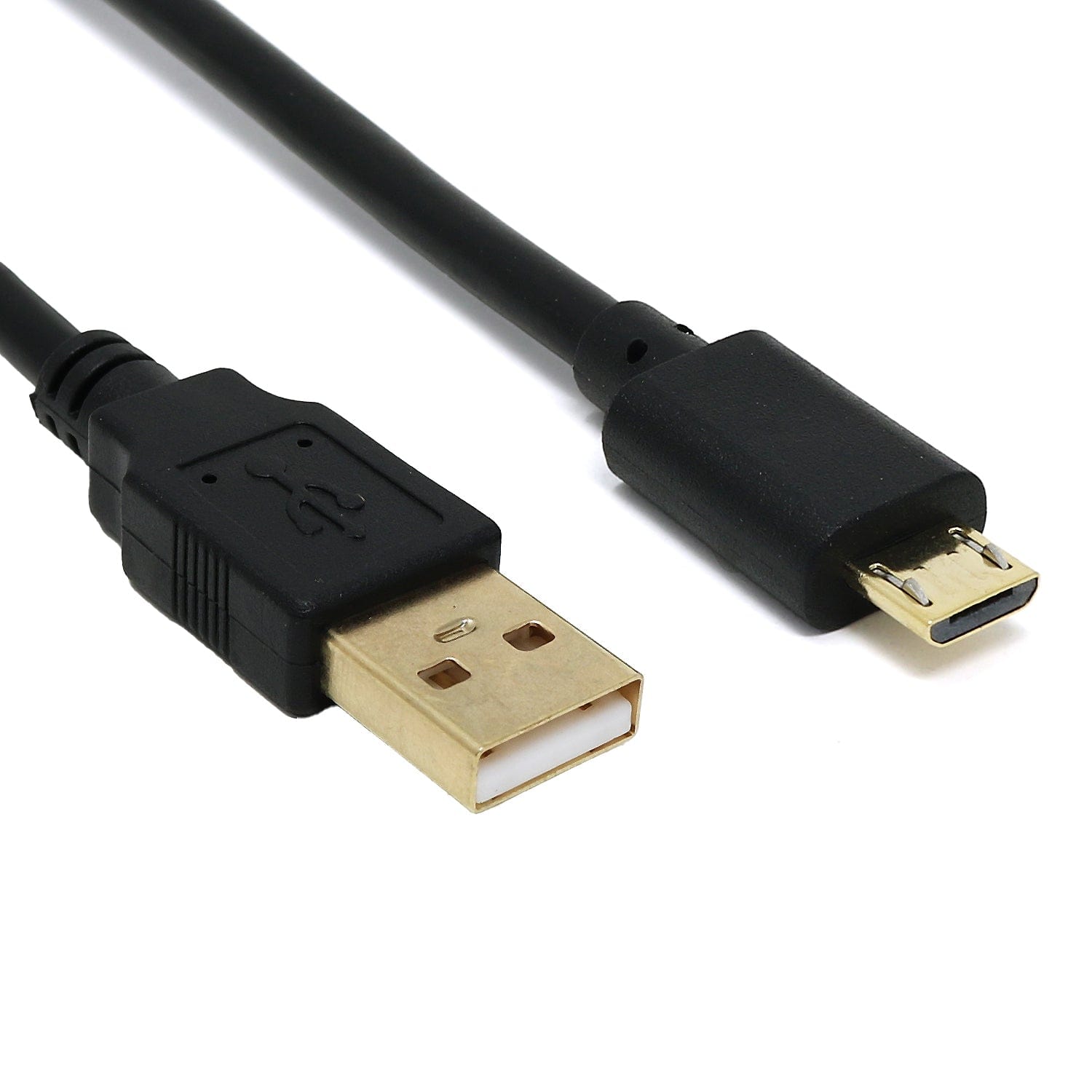
USB-A to Micro-USB Cable - The Pi Hut
The Pi HutUSB-A to Micro-USB Cable
Sale priceFrom £1.50 incl. VAT excl. VAT
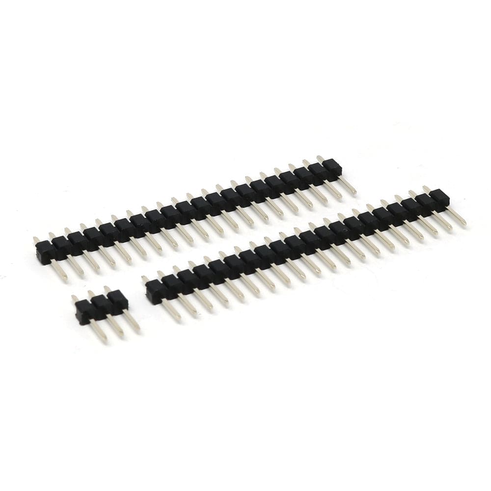
Male Header Set for Raspberry Pi Pico - The Pi HutMale Header Set for Raspberry Pi Pico - The Pi Hut
The Pi HutMale Header Set for Raspberry Pi Pico
Sale price £1 incl. VAT excl. VAT
Get Started with MicroPython on Raspberry Pi Pico - 2nd EditionGet Started with MicroPython on Raspberry Pi Pico - 2nd Edition

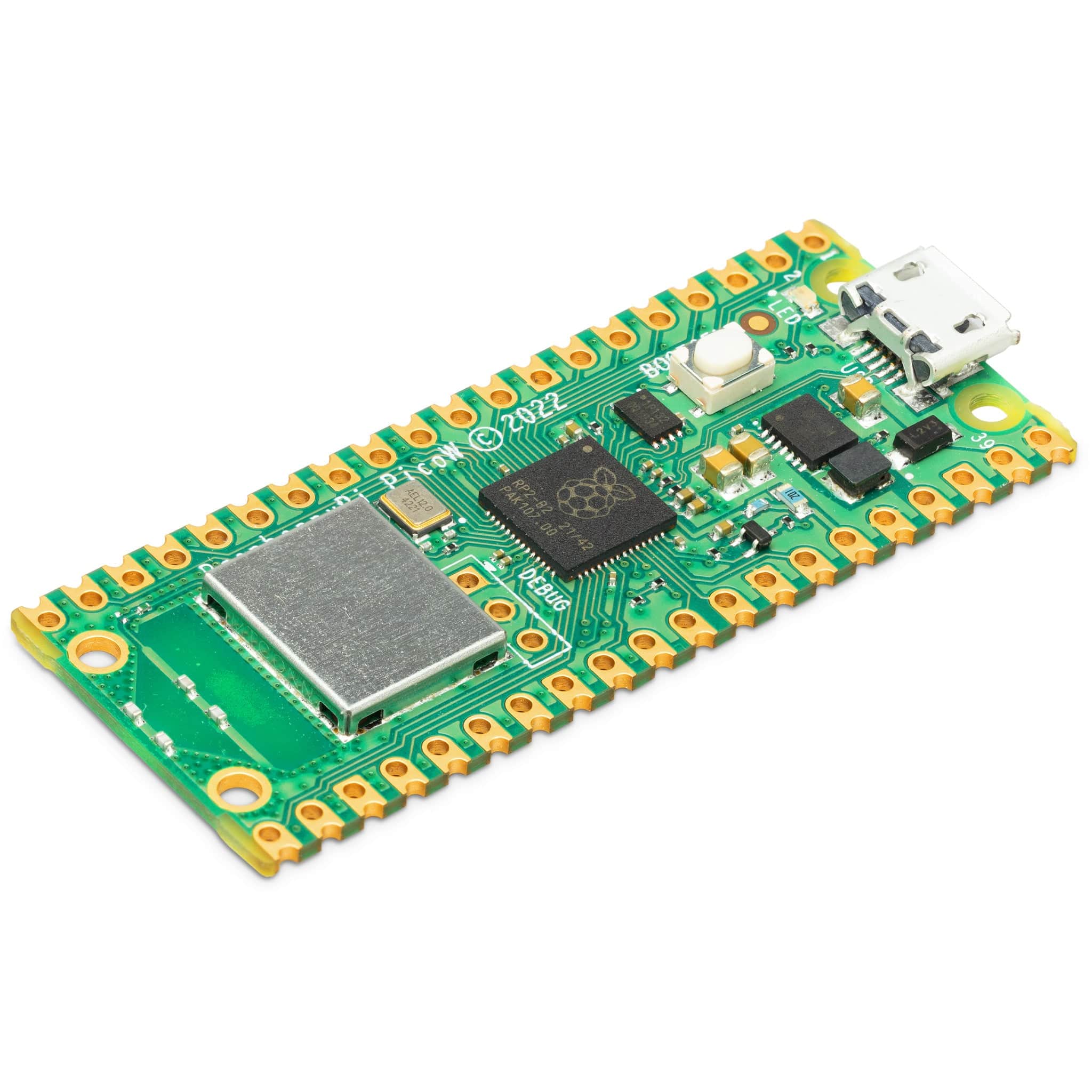
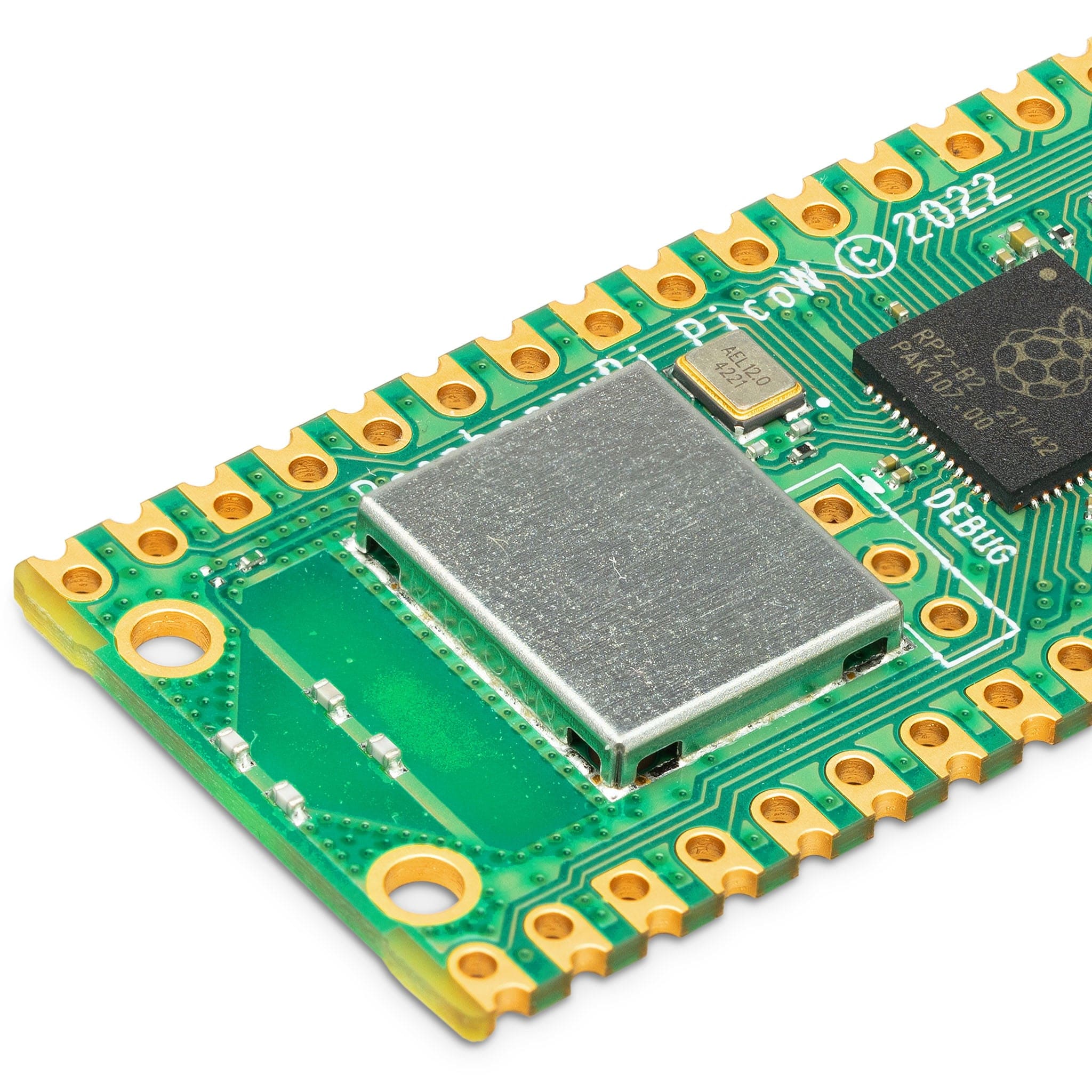
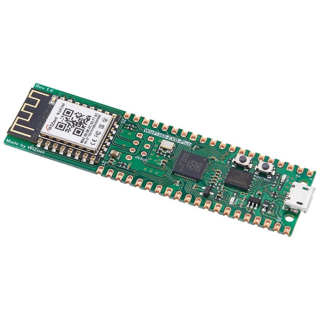
The WizFi360-EVB-Pico is based on the Raspberry Pi Pico/RP2040 and adds Wi-Fi connectivity using a WizFi360 module. It is pin-compatible with the Raspberry Pi Pico board and is ideal for IoT solution development.

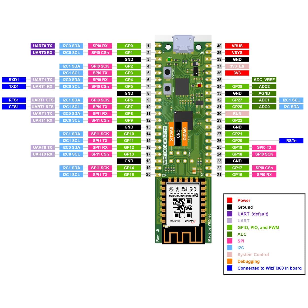
The WizFi360 pinout is directly connected to the GPIO of RP2040 as shown in the pinout image further down the page. It has the same pinout as the Raspberry Pi Pico board however GPIO4, GPIO5, GPIO6, GPIO7, and GPIO20 are connected to the WizFi360 module. These pins enable UART communication with the WizFi360 to use the WiFi function. If you are using the Wi-Fi function, these pins cannot be used for any other purpose.

The RP2040 GPIO used by the WizFi360-EVB-Pico is as follows:

I/O Name Description
O GPIO4 Connected to RXD1 on WizFi360
I GPIO5 Connected to TXD1 on WizFi360
O GPIO6 Connected to RTS1 on WizFi360
I GPIO7 Connected to CTS1 on WizFi360
O GPIO20 Connected to RST on WizFi360
I GPIO24 VBUS sense - high if VBUS is present, else low
O GPIO25 Connected to user LED
I GPIO29 Used in ADC mode (ADC3) to measure VSYS/3

Apart from GPIO and ground pins, there are 7 other pins on the main 40-pin interface:

Pin # Name Description
40 VBUS Micro-USB input voltage, connected to micro-USB port pin 1. Nominally 5V.
39 VSYS Main system input voltage, which can vary in the allowed range 4.3V to 5.5V, and is used by the onboard LDO to generate the 3.3V .
37 3V3_EN Connects to the onboard LDO enable pin. To disable the 3.3V (which also de-powers the RP2040 and W5100S), short this pin low.
36 3V3 Main 3.3V supply to RP2040 and W5100S, generated by the onboard LDO.
35 ADC_VREF ADC power supply (and reference) voltage, and is generated on W5100S-EVB-Pico by filtering the 3.3V supply.
33 AGND Ground reference for GPIO26-29.
30 RUN RP2040 enable pin, To reset RP2040, short this pin low.

Features

  • RP2040 microcontroller with 2MByte Flash
    • Dual-core cortex M0+ at up to 133MHz
    • 264kByte multi-bank high performance SRAM
    • External Quad-SPI Flash with eXecute In Place (XIP)
    • High-performance full-crossbar bus fabric
    • 30 multi-function General Purpose IO (4 can be used for ADC)
      • 1.8-3.3V IO Voltage (NOTE. Pico IO voltage is fixed at 3.3V)
    • 12-bit 500ksps Analogue to Digital Converter (ADC)
    • Various digital peripherals
      • 2 × UART, 2 × I2C, 2 × SPI, 16 × PWM channels
      • 1 × Timer with 4 alarms, 1 × Real Time Counter
    • 2 × Programmable IO (PIO) blocks, 8 state machines total
    • Flexible, user-programmable high-speed IO
    • Can emulate interfaces such as SD Card and VGA
  • Includes WizFi360-PA
    • WiFi 2.4G, 802.11 b/g/n
    • Support Station / SoftAP / SoftAP+Station operation modes
    • Support “Data pass-through” and “AT command data transfer” mode
    • Support serial AT command configuration
    • Support TCP Server / TCP Client / UDP operating mode
    • Support configuration of operating channel 0 ~ 13
    • Support auto 20MHz / 40MHz bandwidth
    • Support WPA_PSK / WPA2_PSK encryption
    • Support built-in unique MAC address and user-configurable
    • Industrial grade (operating temperature range: -40 ° C ~ 85 ° C)
    • CE, FCC certification
  • 16M-bit Flash Memory
  • Micro-USB B port for power and data (and for reprogramming the Flash)
  • 40 pin 21×51 ‘DIP’ style 1mm thick PCB with 0.1″ through-hole pins also with edge castellations
  • 3-pin ARM Serial Wire Debug (SWD) port
  • Built-in LDO
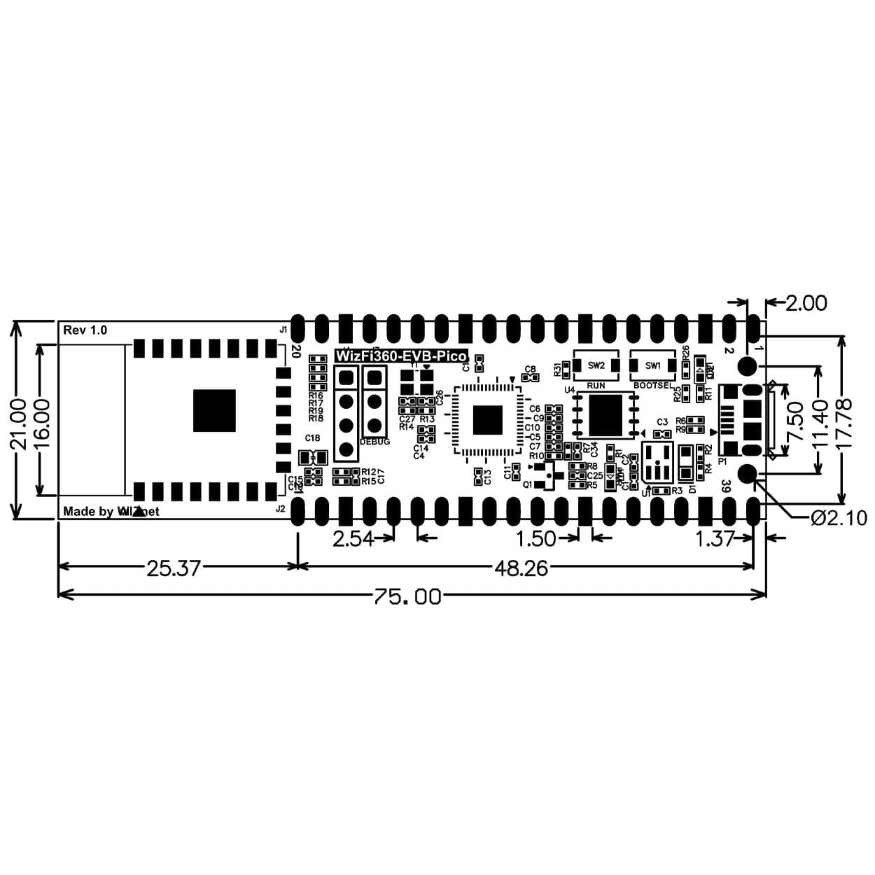
  • Dimensions: 75mm x 21mm
  • Operating Conditions
    • Operation Temperature MAX: 85C (including self-heating)
    • Operation Temperature MIN: -20C
    • VBUS: DC 5V (+/- 10%)
    • VSYS Min: DC 4.3V
    • VSYS Max: DC 5.5V

Resources

Pinout

Payment & Accreditations

Payment methods
Visa Mastercard Maestro PayPal Amazon Klarna

Your payment information is processed securely. We do not store credit card details nor have access to your credit card information.

Accreditations