TTL UART to Ethernet Mini Module
Price:
Sale price
£11.60
Stock:
Quantity:
Login / Signup
Cart
Your cart is empty
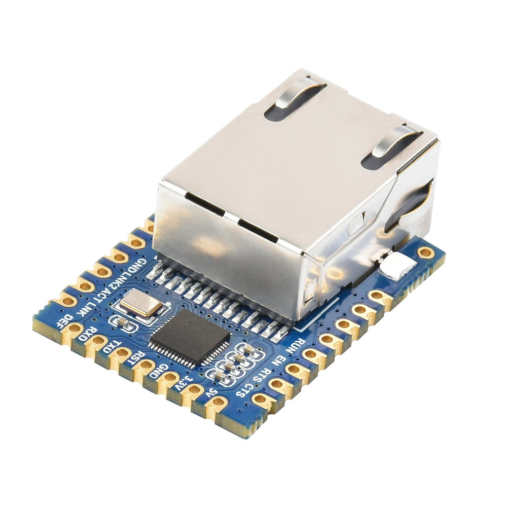
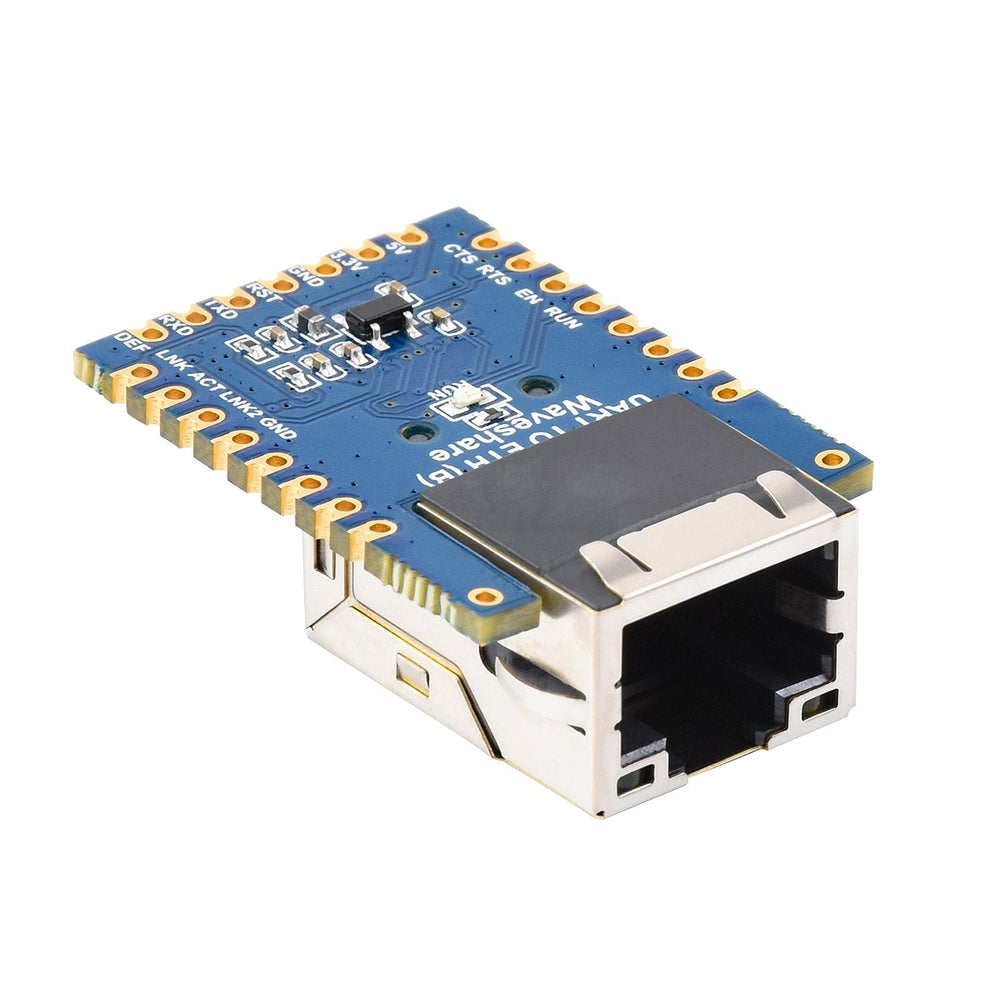
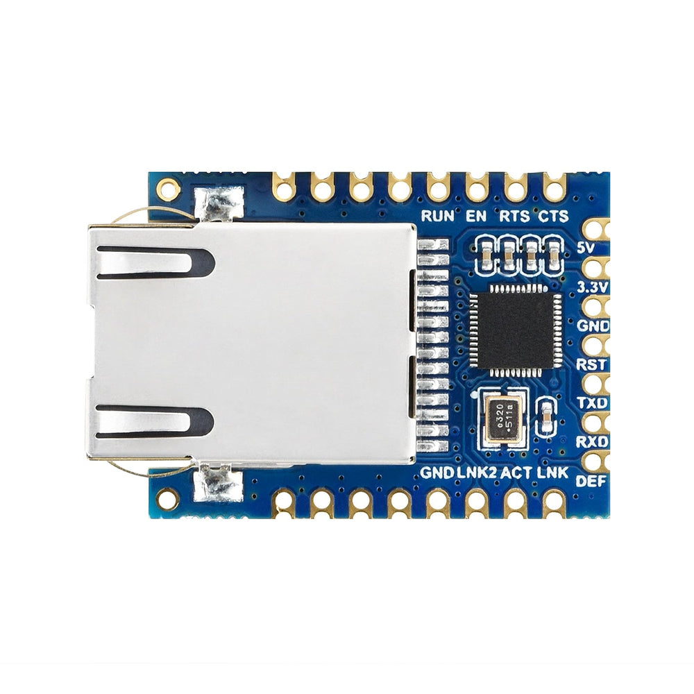
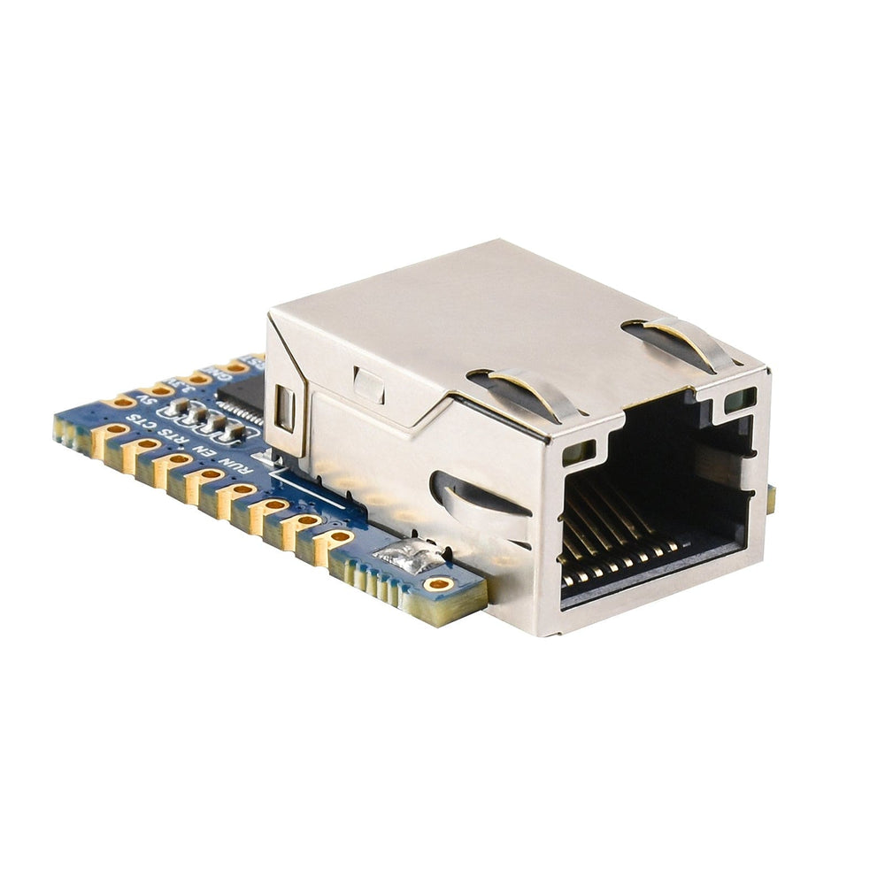
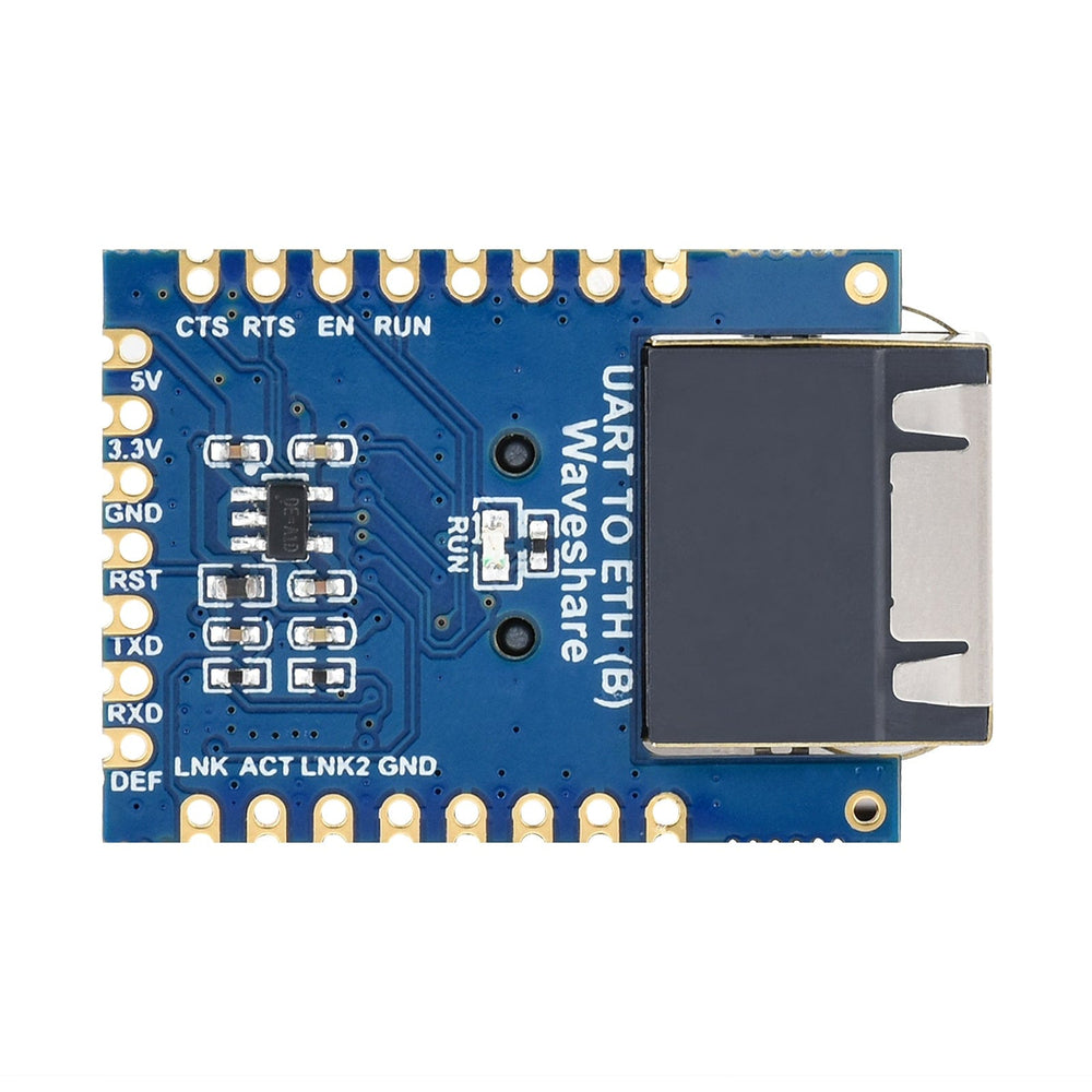
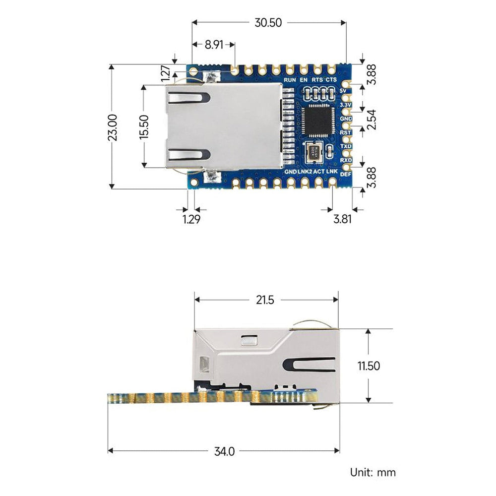
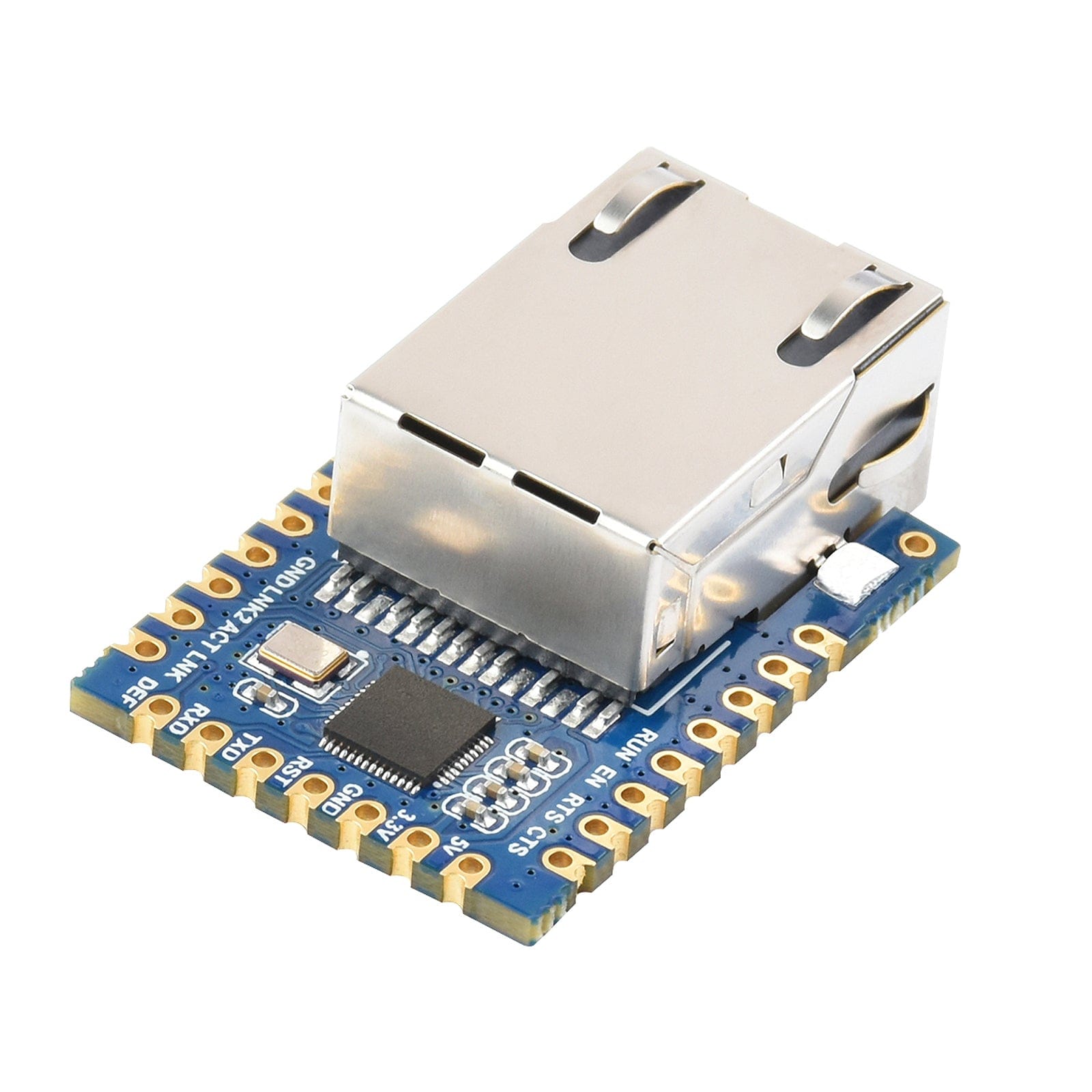
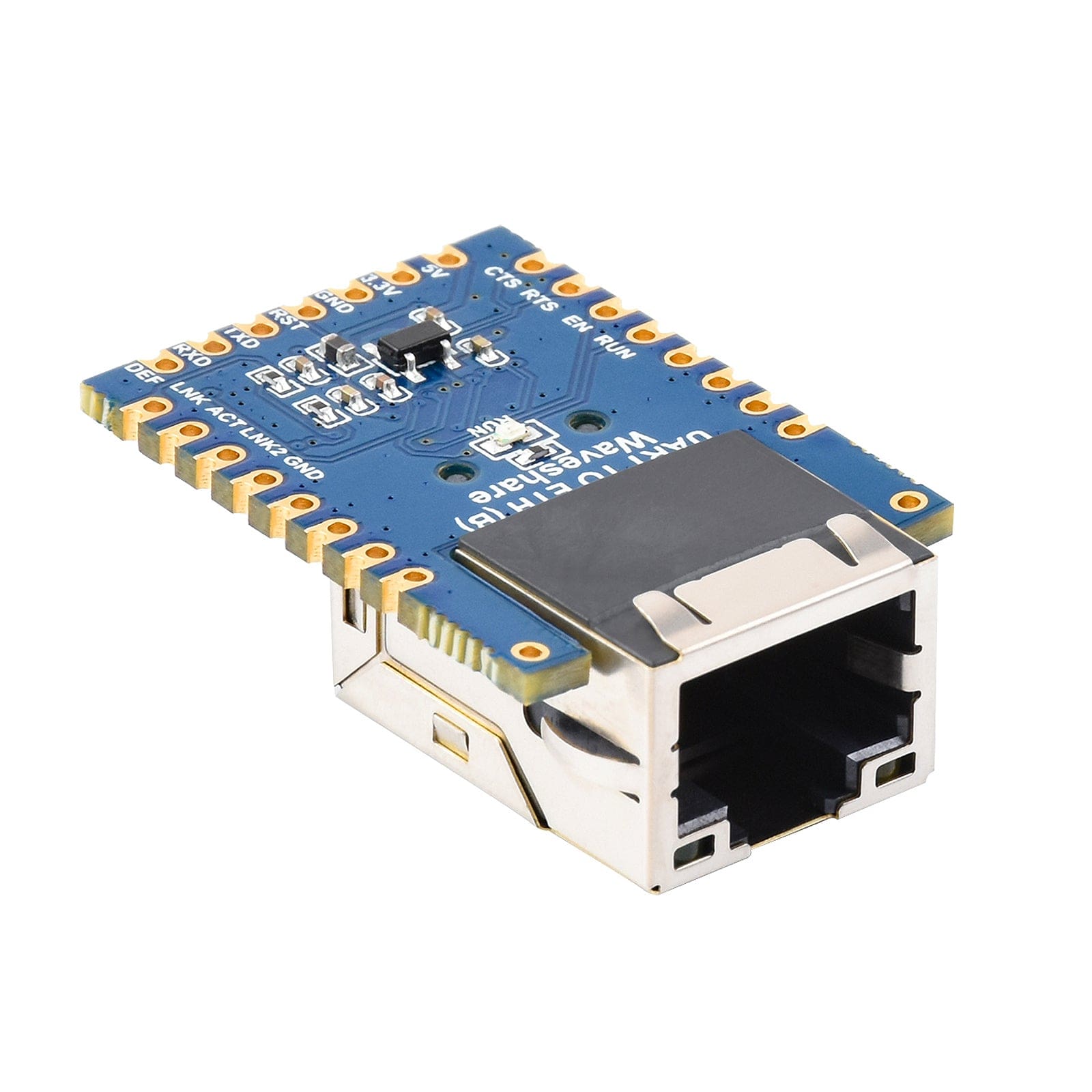
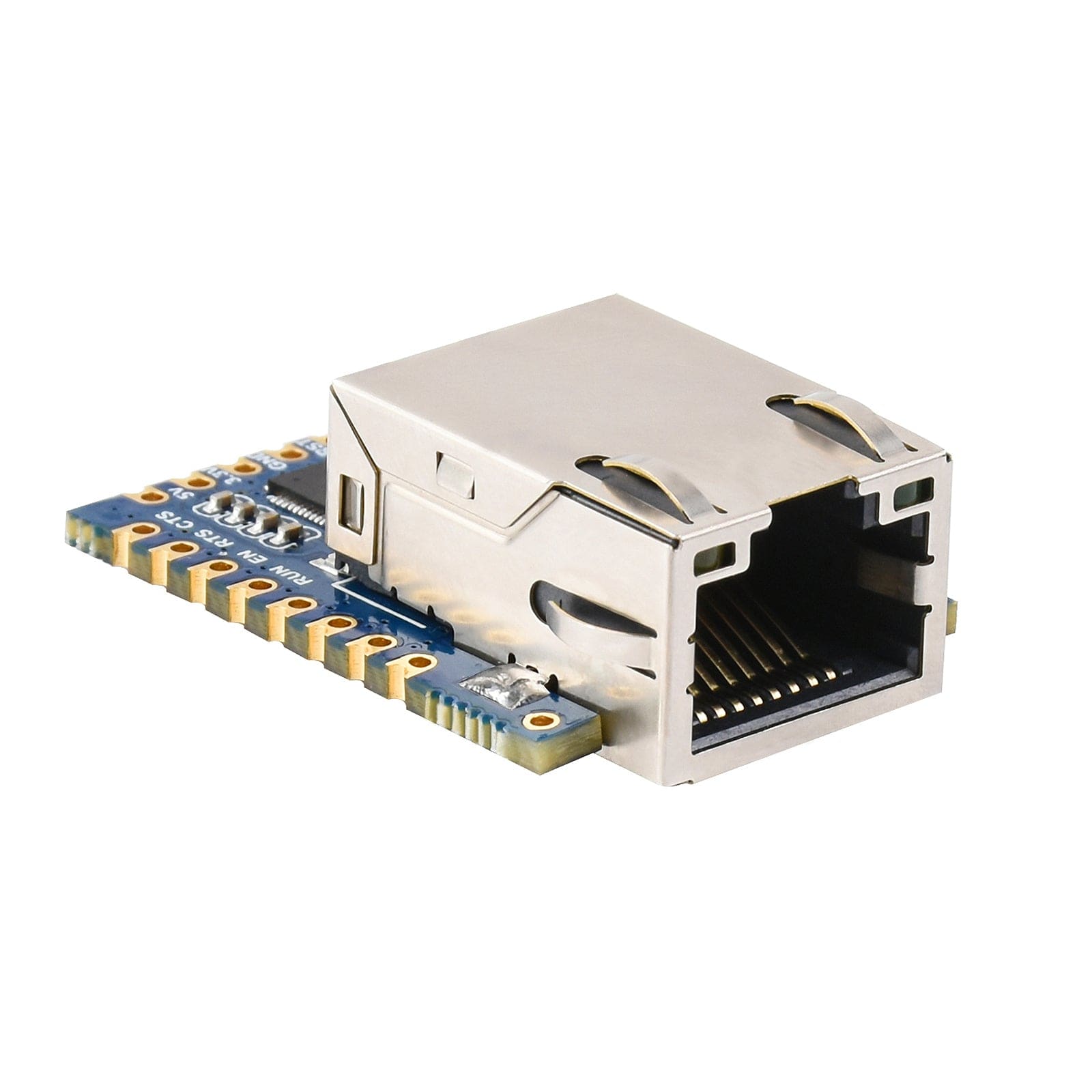
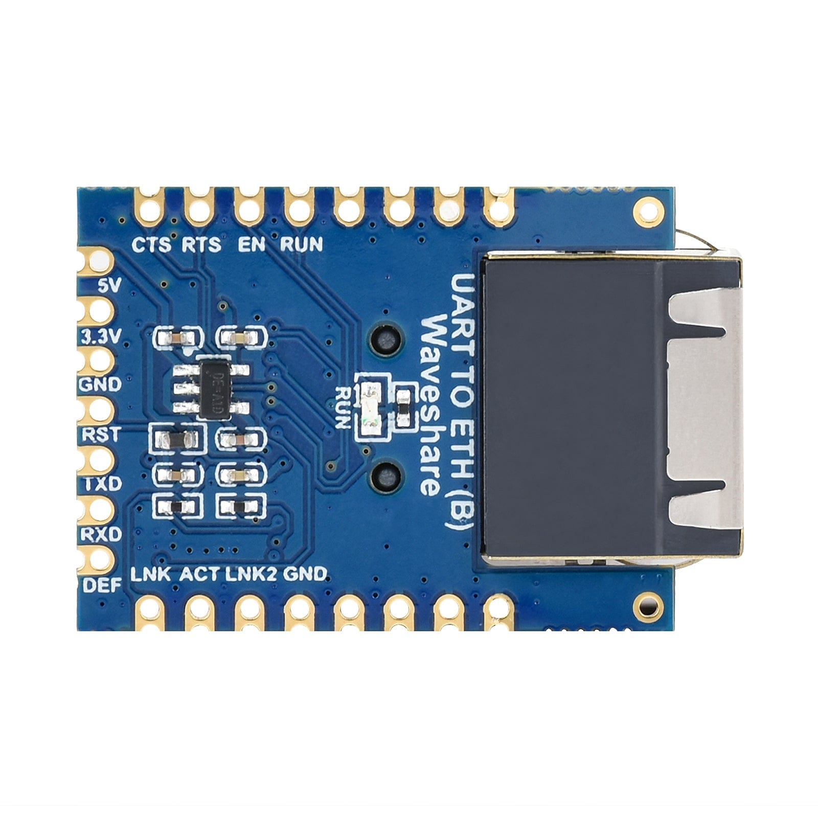
This module provides an easy way to communicate between TTL UART and Ethernet, allowing bi-directional transparent data transmission. Featuring castellated holes and highly integrated packaging for a compact and easy integration into a variety of applications. With its ease of use, multi-communication modes (TCP Server / TCP Client / UDP Multicast / UDP Mode) Modbus Gateway & NTP Protocol Support, a fast data rate, low power consumption and high stability. it's ideal for your next project!

| Product Description | Castellated holes module |
| Basic Function | Bi-directional transparent data transmission between serial port and Ethernet |
| Ethernet | Common network port |
| Isolation Protection | N/C |
| UART Port | TTL |
| Power Supply | Pinheader / pads |
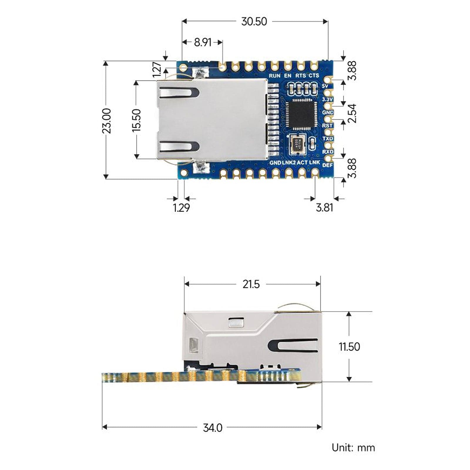
| Dimensions | 34×23×11.5mm |
| Application Scenarios | Can be used as Serial server, Modbus gateway, MQTT gateway, suitable for applications like data acquisition, IoT gateway, safety & security IoT, and intelligent instrument monitoring. |
| UART Specification - | |
| Baudrate | 300 ~ 115200 bps |
| Parity Bit | None, odd, even, mark, space |
| Data Bit | 5 ~ 9 bits |
| Flow Control | Support |
| Software - | |
| Protocol | ETHERNET, IP, TCP, UDP, HTTP, ARP, ICMP, DHCP, DNS |
| Configuration | Host, web browser, device management functions library |
| Communication Method | TCP/IP direct communication, VCOM |
| Operating Mode | TCP server, TCP client, UDP Group, UDP |
| Modbus Gateway | Modbus TCP to RTU |
| Other Functions | User-defined heartbeat/registration packet, User-defined web page... |
| Other - | |
| Operating Temperature | -40℃ ~ 85℃ |
| Humidity Range | 5% ~ 95% relative humidity |

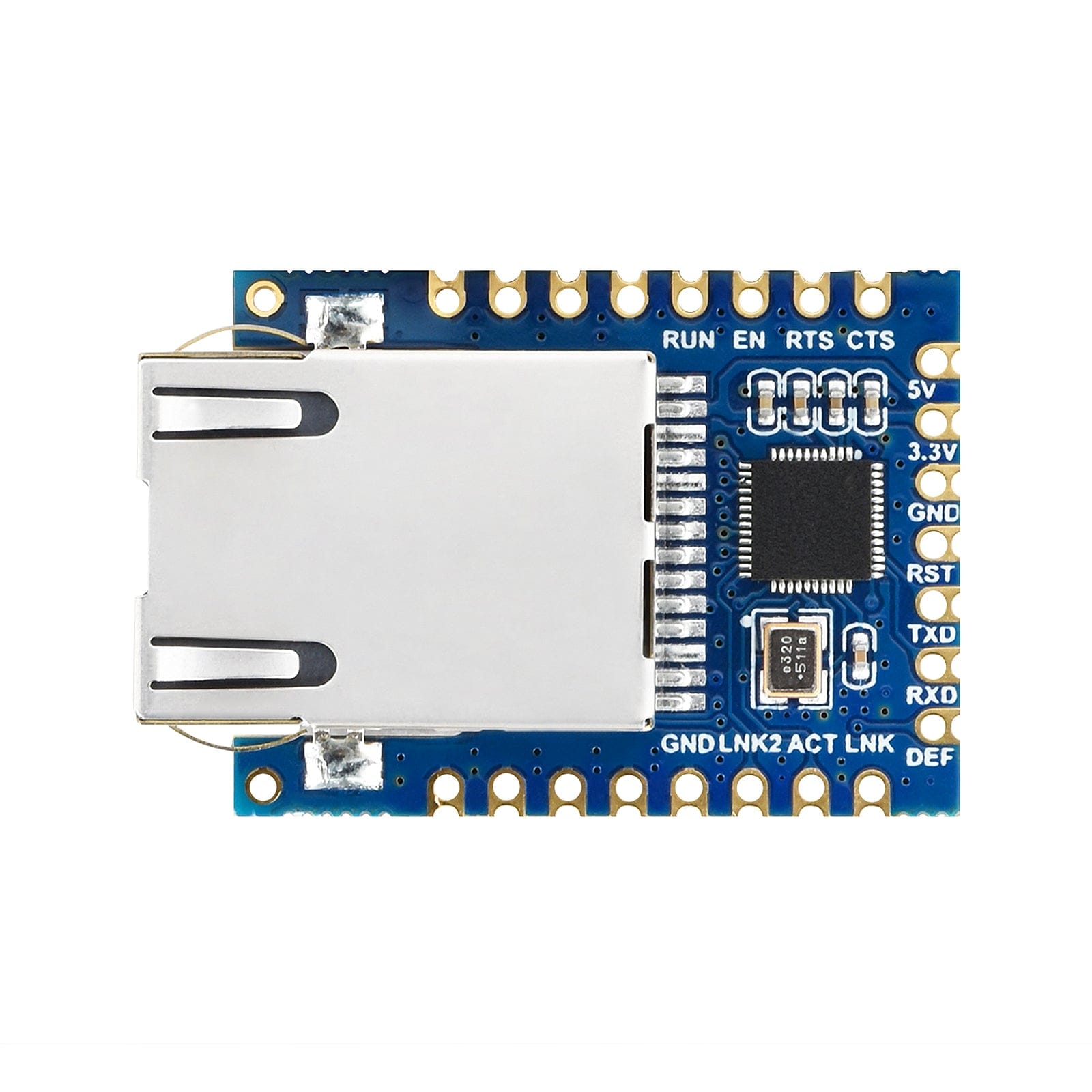
| Pin | Model | Description |
| 5V | Power | 5V Power Input |
| 3.3V | Power | 3.3V Power Input |
| GND | Ground | Ground |
| RST | Reset | Reset pin, low active. It is recommended to use max811reus or a similar reset chip. Noise can be filtered by a 0.1u capacitor. Low-level minimum time 100ns. |
| TXD | OUT | Serial data transmitting pin of the module, 3.3V TTL level, can be connected to RXD of user MCU. |
| RXD | IN | Serial data receiving pin of the module, 3.3V TTL level, can be connected to the user MCU's TXD. |
| DEF | IN | When the parameter is reset to 0 and held for more than 1 second, the module will restart with the default IP of 192.168.1.254, static IP mode, 255.255.255.0 gateway, and 192.168.1.1 gateway. You can also set your own reset parameters with the param.txt configuration file. |
| RUN | OUT | Working indicator, the chip works properly, and will output a square wave with a period of 2 seconds. You can connect a 4.7K resistor and then connect the LED to the ground and the LED is on indicating the chip has been working. |
| EN | OUT | The 485 transmit controller, normally 0, becomes 1 when the module sends data to the serial port. It can be connected directly to the TXD_EN pin of the MAX485 chip. |
| RTS | OUT | Hardware flow control output. After the flow control is set to CTS/RTS, DTR/DSR, RTS=0 normally, if RTS=1, it means the module can't receive data and the user MCU should stop sending data to the module. |
| CTS | IN | Hardware flow control input, when the chip is configured for CTS/RTS, DSR/DTR serial mode, only when CTS=0, the chip serial port will output data to the outside. |
| GND | Ground | Ground |
| LINK2 | OUT | When it is 0, it indicates that the module RJ45 network cable is connected. |
| ACT | OUT | Data indicator. When it is 0, it indicates that there is data being sent and received at the serial port. But when there is data, this pin will jump between 0 and 1. ACT=1, which cannot be used as a flag for no data communication. |
| LINK | OUT | TCP connection indicator. When it is 0, the module has established TCP/UDP connection with the network server, and the module can send and receive data normally. If the network cable is unplugged at this time, the LINK will change to 1. |
