Login / Signup
Cart
Your cart is empty


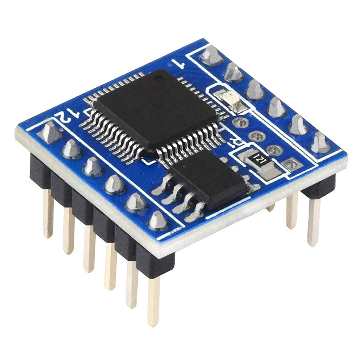
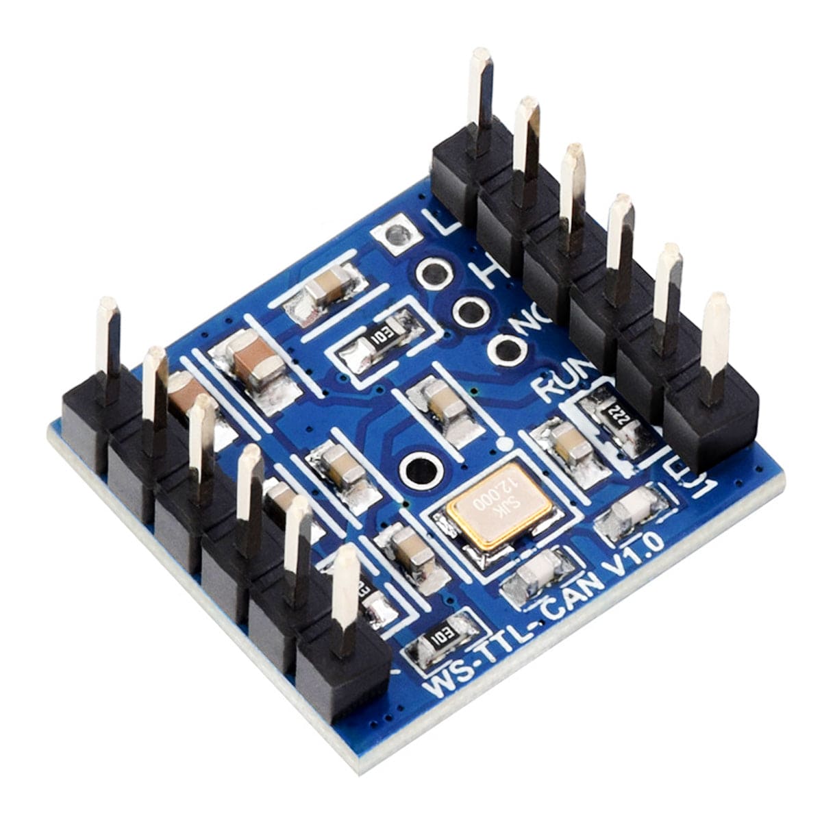
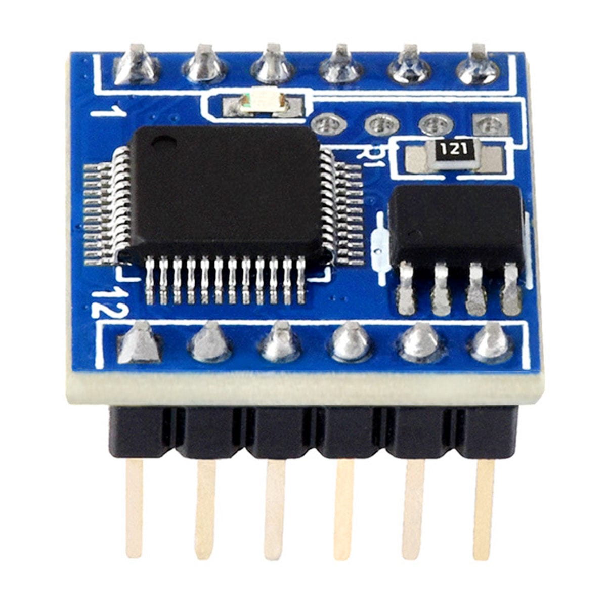
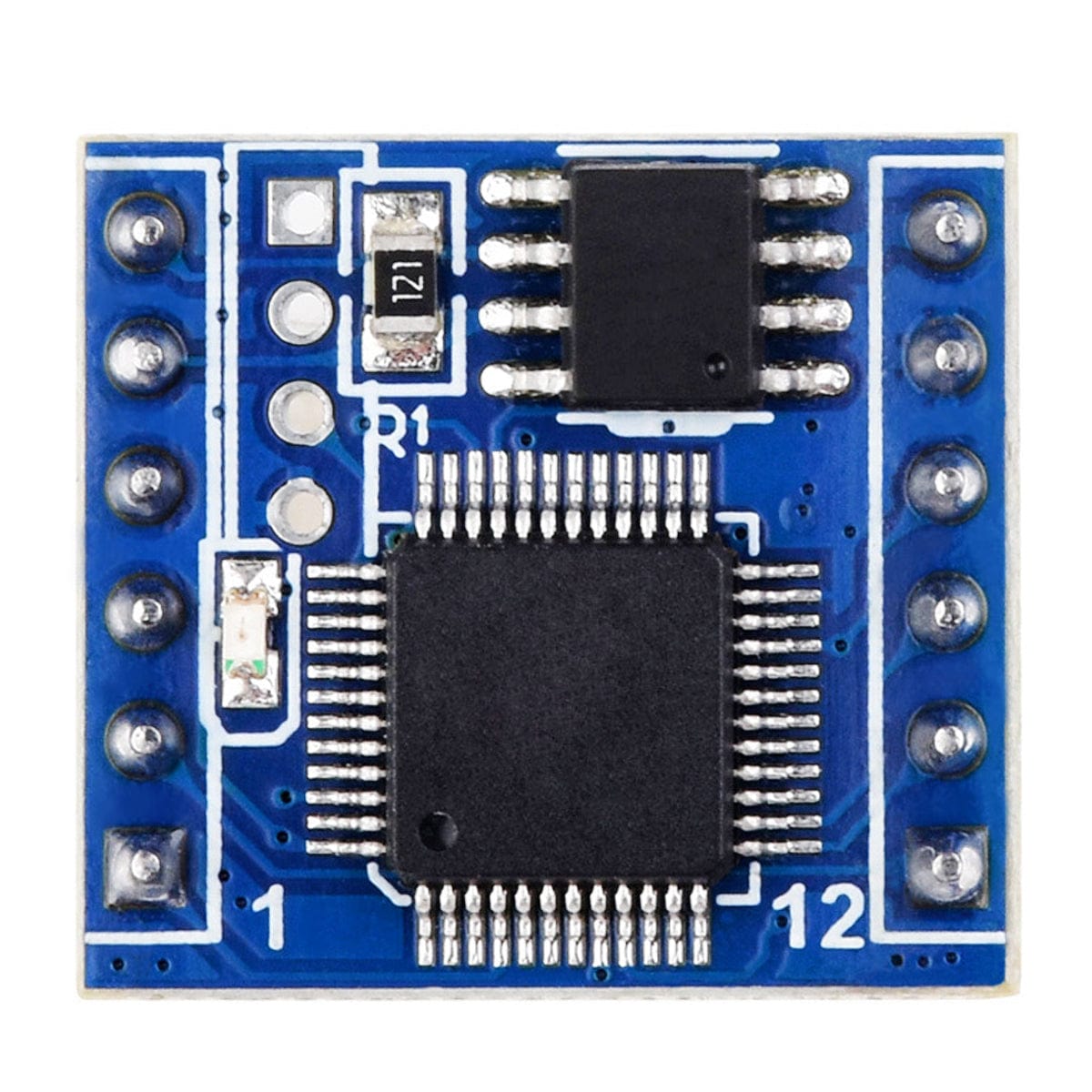
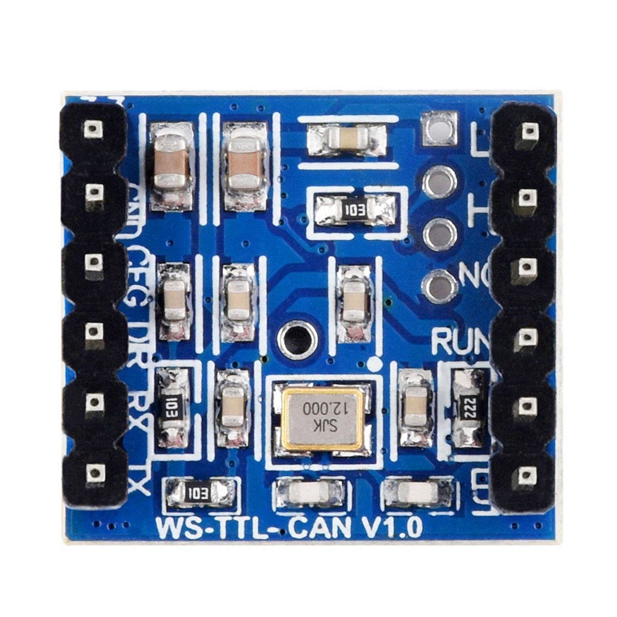
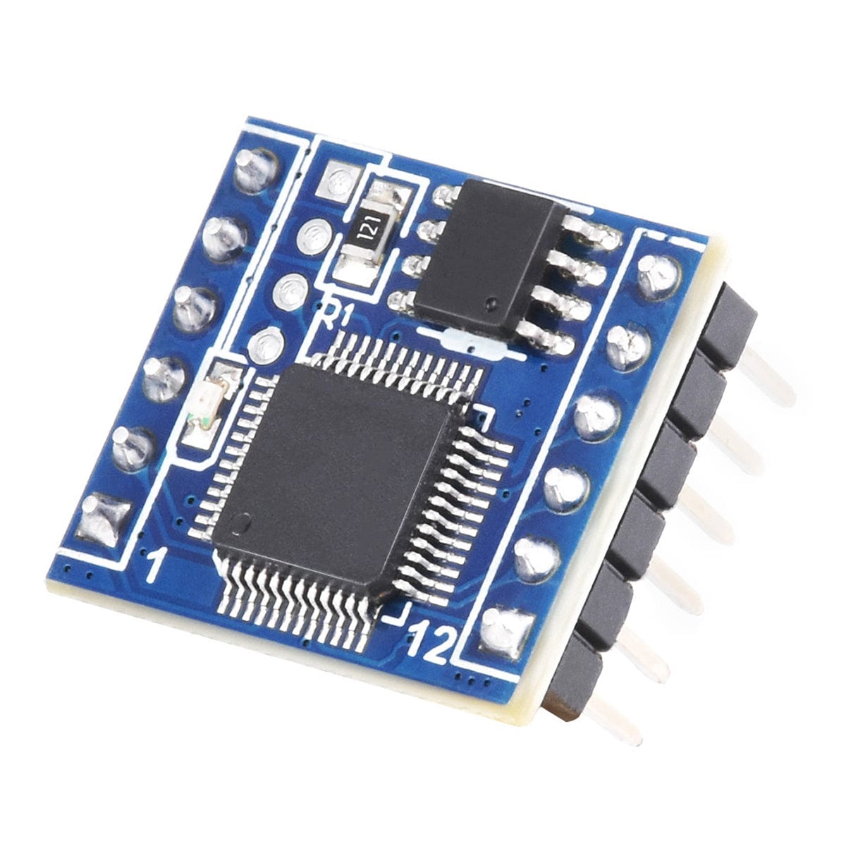
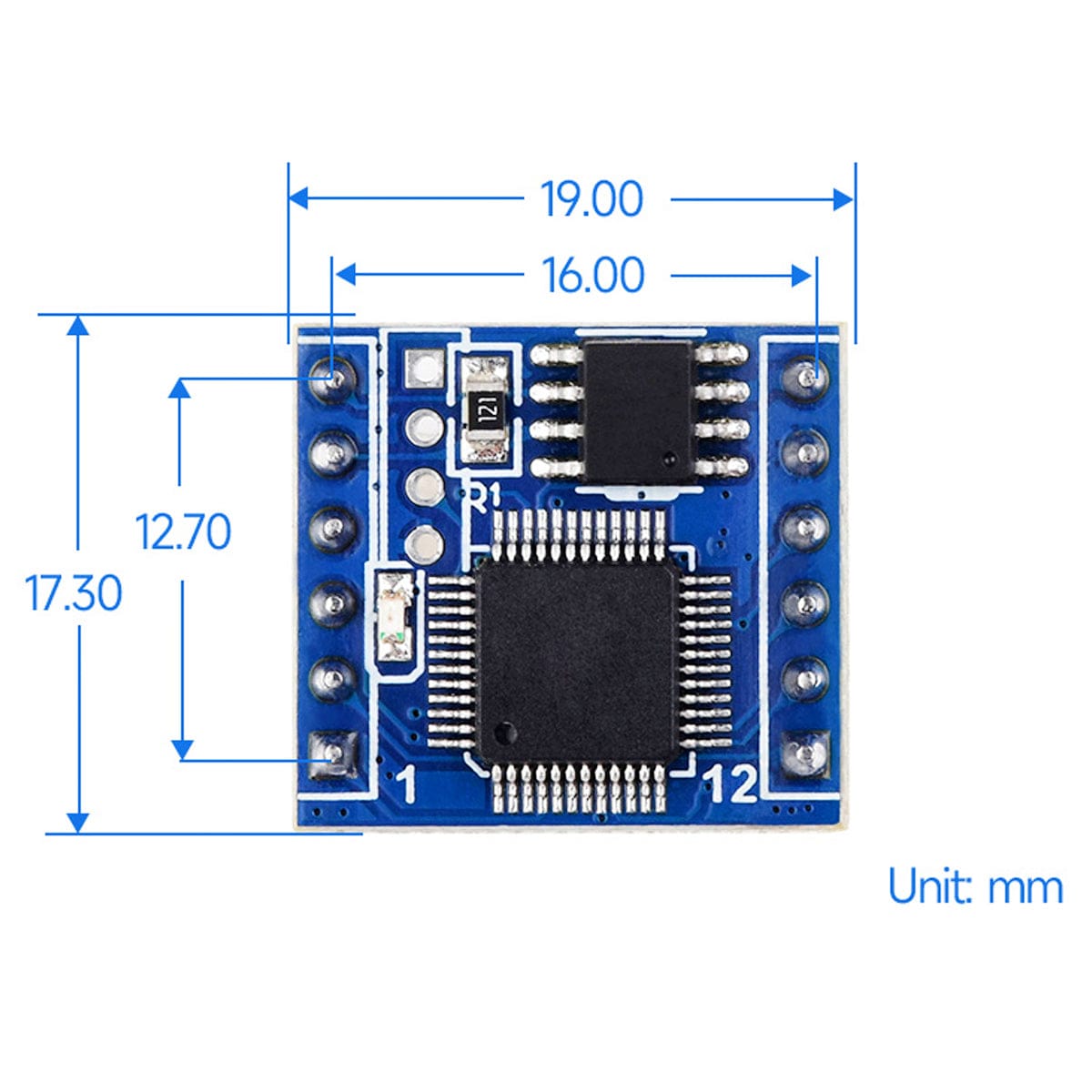
This TTL UART to CAN module has a high-performance MCU and a CAN transceiver chip, making it small, low-power, and easy to embed into various projects. It includes a built-in protocol for TTL and CAN conversion, allowing for easy data communication conversion between TTL and CAN interfaces through simple configuration steps.
Operating on a 3.3V voltage for the TTL interface, the module is compatible with both CAN 2.0A (standard frame) and CAN 2.0B (extended frame). It features fourteen configurable filters, allowing it to receive only the specific range and type of CAN bus data needed. You can select from four operating modes: transparent conversion, transparent with identifiers conversion, format conversion, and Modbus RTU protocol conversion.


| NO. | PIN DEFINITION | DESCRIPTION |
| 1 | UART_LED | TTL communication indicator signal pin, high level for no data, low level for data transmission |
| 2 | CAN_LED | CAN communication indicator signal pin, high level for no data, low level for data transmission |
| 3 | RUN_LED | System running indicator signal pin, toggles between high and low levels (approx. 1Hz) when the system is working normally; Outputting high level when CAN bus is abnormal |
| 4 | NC | Reserved pin, not connected |
| 5 | CAN_H | CAN differential positive, built-in 120Ω resistor |
| 6 | CAN_L | CAN differential negative, built-in 120Ω resistor |
| 7 | 3.3V | Power input, 3.3V@40mA |
| 8 | GND | Ground |
| 9 | CFG | Reset/restore to factory setting, pull low within 5s for resetting or more than 5s for restoring factory setting |
| 10 | DIR | RS485 direction control |
| 11 | RXD | TTL RX |
| 12 | TXD | TTL TX |


