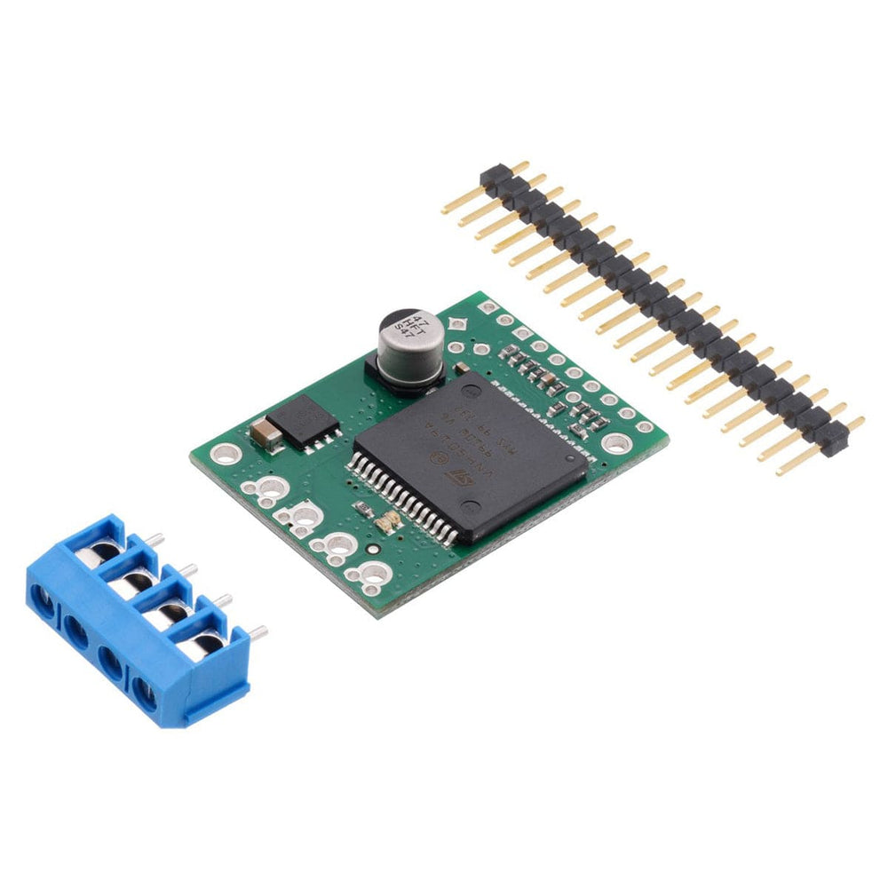
Pololu VNH5019 Motor Driver Carrier
Price:
Sale price
£28.80
Stock:
Quantity:
Cart
Your cart is empty

This Pololu motor driver board handles high-power DC motors with a continuous 12A rating (30A peak) and operates from 5.5-24V supply voltage. It features built-in protections, current sensing, status LEDs, and can be controlled with standard 3.3V or 5V microcontrollers using simple PWM and direction signals.
This Pololu carrier board for ST’s VNH5019 motor driver IC operates from 5.5 to 24V and can deliver a continuous 12A (30A peak).
It works with 2.5 to 5V logic levels, supports ultrasonic (up to 20 kHz) PWM, and features current sense feedback (an analog voltage proportional to the motor current).
Along with built-in protection against reverse-voltage, over-voltage, under-voltage, over-temperature, and over-current, these features make this product a great general-purpose motor driver.
This module is a compact breakout board for ST’s high-power VNH5019 motor driver IC, a fully integrated H-bridge that can be used for bidirectional speed control of a single brushed DC motor. The basic operation of the driver is summarized below, but we also recommend careful reading of the VNH5019 datasheet before using this product. The board incorporates most of the components of the typical application diagram on page 14 of the VNH5019 datasheet, including pull-up and current-limiting resistors and a FET for reverse battery protection. It ships fully populated with its SMD components, including the VNH5019, as shown in the product picture.
Many motor controllers or speed controllers can have peak current ratings that are substantially higher than the continuous current rating; this is not the case with these motor drivers, which have a 30A continuous rating and over-current protection that can kick in as low as 30A (50A typical). Therefore, the stall current of your motor should not be more than 30A. (Even if you expect to run at a much lower average current, the motor can still draw short bursts of high currents, such as when it is starting, if special steps are not taken.)
Warning: This product can get hot enough to burn you long before the chip overheats. Take care when handling this product and other components connected to it.
** While the overvoltage protection typically kicks in at 27V, it can trigger at voltages as low as 24V, so we do not recommend using this motor driver with 24V batteries, which significantly exceed 24V when fully charged.
The motor and motor power connections are on one side of the board and the control connections are on the other side. The motor power supply connects to the large VIN and GND pins; it should be between 5.5 and 24 V and have the ability to deliver the potentially high currents the motor will require. The logic power supply (typically 2.5 – 5 V) connects to the small VDD and GND pads on the control side of the board and is used to power the internal pull-ups on the ENA and ENB enable lines. Any control input voltage above 2.1 V is guaranteed to be high, so this driver can be directly interfaced into both 3.3 and 5 V systems.
The following diagram shows the minimum connections required for interfacing this motor driver with a microcontroller:

In this configuration, the motor direction is determined by the states of the INA and INB pins and motor speed is controlled by the duty cycle of a PWM signal supplied to the driver’s PWM pin. The PWM pin is pulled low on the board, so the motor driver outputs are effectively disabled by default; the INA and INB pins are floating (they are not pulled to any particular default voltage). See the truth tables in the VNH5019A-E datasheet for more information on how the INA, INB, and PWM pins affect the driver outputs, OUTA and OUTB. Note that it is also possible to save a microcontroller I/O line by directly PWMing the INA and INB pins while holding the PWM pin high (e.g. by connecting it directly to VDD), but the trade-off is that this only works at low frequencies (a few hundred Hertz or less).
This board features motor indicator LEDs that can be used to test that motor driver outputs are working as expected before actually connecting a motor (this can be especially helpful in detecting problems due to insufficient power supplies). The LED brightness increases with motor speed, and the LED colour changes with direction.
The current sense output is approximately 140 mV/A. Note that the output is only active while the H-bridge is driving; it is inactive (low) when the driver is coasting (motor outputs are high impedance) or braking. During the coast portion of the drive/coast cycle, current will continue to circulate through the motor, but the voltage on the FB pin will not accurately reflect the motor current.
The motor driver IC has a maximum continuous current rating of 30 A. However, the chips by themselves will overheat at lower currents (see the table above for typical values). The actual current you can deliver will depend on how well you can keep the motor driver cool. The carrier’s printed circuit board is designed to draw heat out of the motor driver chips, but performance can be improved by adding a heat sink. In our tests, we were able to deliver short durations (on the order of milliseconds) of 30 A and several seconds of 20 A without overheating. At 6 A, the chip gets just barely noticeably warm to the touch. For high-current installations, the motor and power supply wires should also be soldered directly instead of going through the supplied terminal blocks, which are rated for up to 16 A.
Warning: This product can get hot enough to burn you long before the chip overheats. Take care when handling this product and other components connected to it.

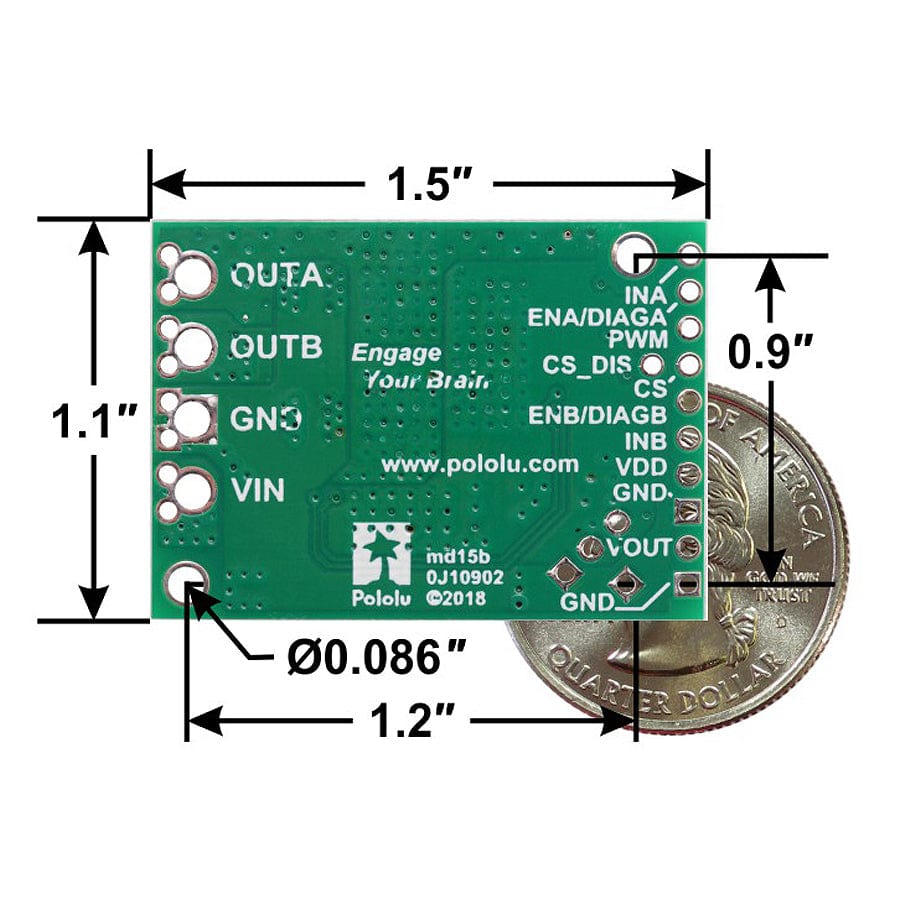
| Pin |
Default State | Description |
| VIN | The connection point for the positive side of the 5.5 – 24 V motor power supply. Since the overvoltage protection can be as low as 24 V, we do not recommend using 24V batteries for VIN. | |
| VDD | The connection point for the positive side of the logic power supply (typically 2.5 – 5 V). The only function of this pin is to power the internal pull-ups on the two enable lines, ENA and ENB. | |
| VOUT | This pin gives you access to the motor power supply after the reverse-voltage protection MOSFET (see the board schematic below). It can be used to supply reverse-protected power to other components in the system, but it should not be used for high currents. This pin should only be used as an output. | |
| GND | Ground connection points for logic and motor power supplies. The control source and the motor driver must share a common ground. | |
| OUTA | Output of half-bridge A (connects to one terminal of a DC motor). | |
| OUTB | Output of half-bridge B (connects to the other terminal of a DC motor). | |
| PWM | LOW | Pulse width modulation input: a PWM signal on this pin corresponds to a PWM output on the motor outputs. |
| INA | FLOAT | Motor direction input A (“clockwise” input). |
| INB | FLOAT | Motor direction input B (“counterclockwise” input). |
| CS | Current sense output. The pin voltage is roughly 140 mV per amp of output current when the CS_DIS pin is low or disconnected. The current sense reading is more accurate at higher currents. The CS pin is designed for PWM frequencies of 5 kHz or higher. If you use a PWM frequency lower than 5 kHz and want to measure the current, we recommend adding an extra capacitor between the CS pin and GND to smooth out the signal. For example, if you use a PWM frequency of 490 Hz and want to measure the current, you should add a 1 µF capacitor (or larger) between CS and GND. (Note that while the CS voltage can potentially exceed 3.3 V at high currents, the current sense circuit should be safe for use with many 3.3V analog inputs. Most MCUs have integrated protection diodes that will clamp the input voltage to a safe value, and since the CS circuit has a 10 kΩ resistor in series with the output, only a few hundred microamps at most will flow through that diode.) | |
| ENA/DIAGA | HIGH | Combination enable input/diagnostic output for half-bridge A. When the driver is functioning normally, this pin acts as an enable input, with a logical high enabling half-bridge A and a logical low disabling half-bridge A. When a driver fault occurs, the IC drives this pin low and half-bridge A is disabled. This pin is connected to VDD through a pull-up resistor on the board. |
| ENB/DIAGB | HIGH | Combination enable input/diagnostic output for half-bridge B. See the description of ENA/DIAGA. |
| CS_DIS | LOW | Disables the current sense output, CS, when high. Can be left disconnected in most applications. |
| Motor driver | VNH5019 |
| Motor channels | 1 |
| Minimum operating voltage | 5.5V |
| Maximum operating voltage | 24V |
| Continuous output current per channel | 0 |
| Peak output current per channel | 30 A |
| Current sense | 0.14 V/A |
| Maximum PWM frequency | 20 kHz |
| Reverse voltage protection? | Y |
| Size | 1.50″ × 1.1″ × 0.30″ |
| Weight | 6.5 g |
You can use the terminal blocks to make your motor and motor power connections, or you can break off an 8×1 section of the header strip and solder it into the smaller through-holes that border the four large motor and motor power pads. Note, however, that the terminal blocks are only rated for 16A, and each header pin pair is only rated for a combined 6A, so for higher-power applications, thick wires should be soldered directly to the board.
The two mounting holes are intended for use with #2 screws (not included).
Your payment information is processed securely. We do not store credit card details nor have access to your credit card information.