Pololu Mini Pushbutton Power Switch with Reverse Voltage Protection - SV
Price:
Sale price
£4.80
Stock:
Quantity:
Cart
Your cart is empty
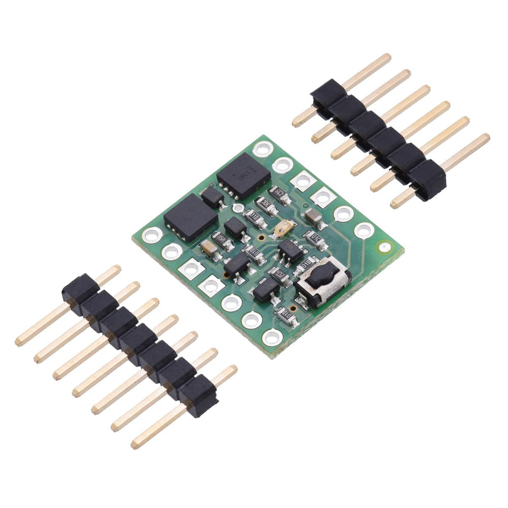

The Pololu Pushbutton Power Switches are sophisticated power control alternatives to bulky mechanical switches.
The main function is pushbutton-based latching power control, where one push turns on power and another push turns it off. Additional control inputs allow advanced applications such as automatic shutdown by the device being powered. This standard-voltage (SV) version operates from 4.5V to 40V and can deliver continuous currents up to around 4A.
Warning: Do not use this switch as an emergency cutoff or similar safety disconnect in applications where failure to cut power could lead to injury or property damage. Please note that this switch has several drawbacks when compared to mechanical switches, so please be sure you fully understand this product before using it in your system.
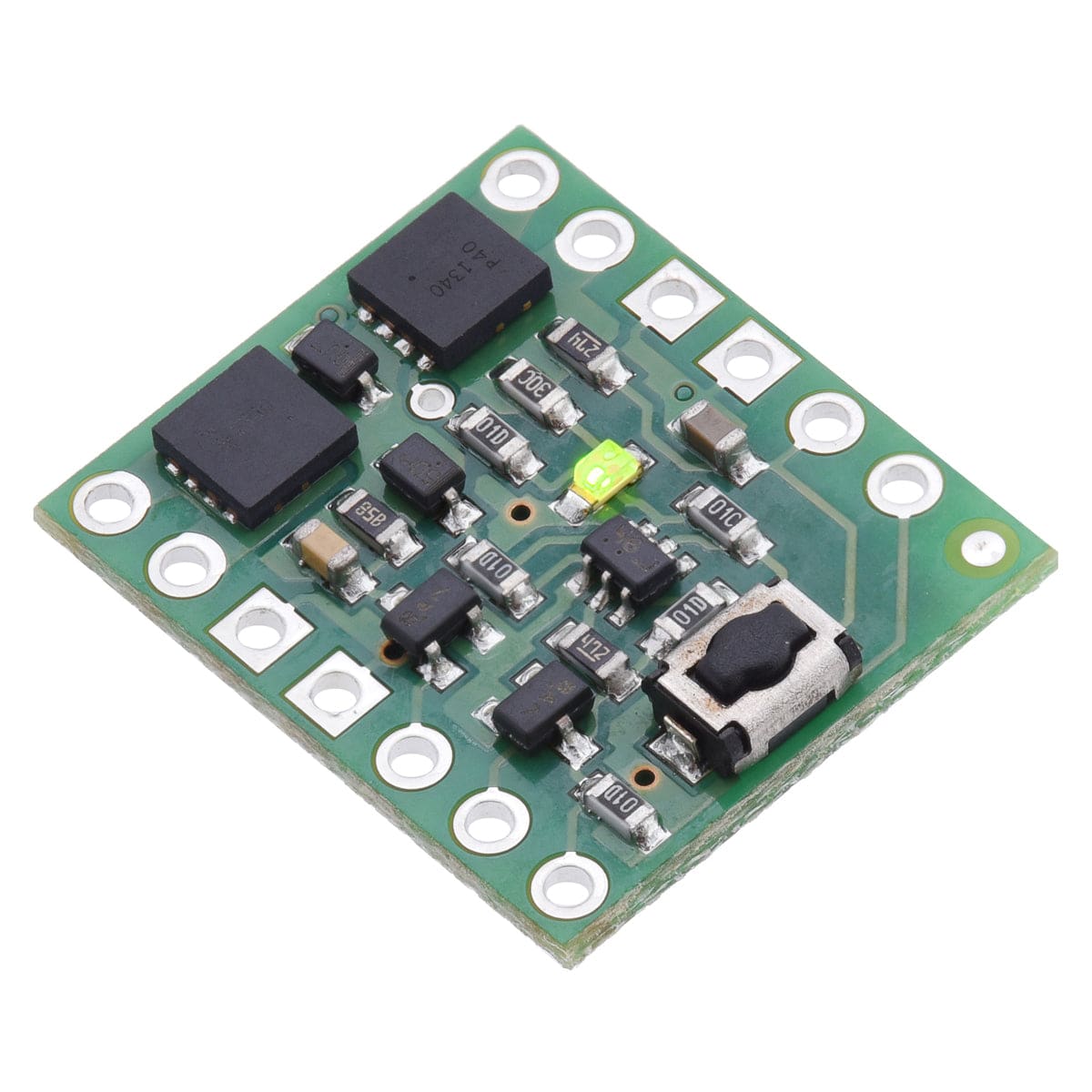
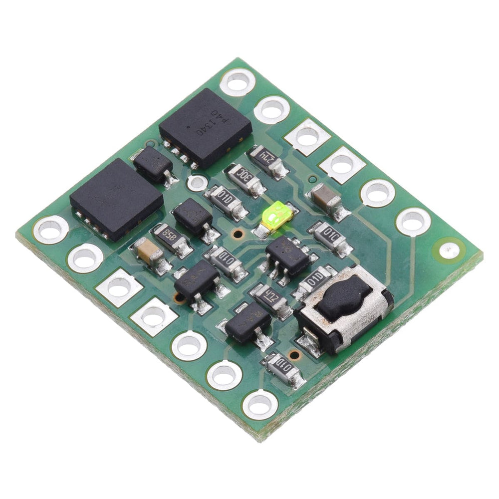
The Pololu Pushbutton Power Switch is a compact, solid-state power switch that features built-in reverse-voltage protection and is controlled by a momentary pushbutton: one push turns on power, and another push turns it off. This is a patented design initially created for use in our own products as an alternative to bulky mechanical switches. Because the switched current does not flow through the mechanical switch, a large variety of small, low-power switches can be used to control a substantial amount of power. The use of momentary switches also allows multiple switches to be used in parallel to control the power to one load.
The board has a small pushbutton already installed and offers convenient points for connecting external pushbuttons or tactile switches in parallel. It also offers several alternate pushbutton connection options that result in push-on-only or push-off-only operation, and additional inputs enable further power control options like allowing the load to turn off its own power, which can be beneficial when used with battery chemistries sensitive to over-discharging.
The switch and control inputs control the state of a latching circuit that, in turn, controls a pair of power MOSFETs through which the main current flows.
The Pololu Pushbutton Power Switch works well in its intended application as a DC power switch for small robots, but because it is fundamentally different from a mechanical power switch, the benefits and drawbacks of the components must be fully considered.
Benefits over mechanical switches:
Drawbacks compared to mechanical switches:

The simplest way to control the Pushbutton Power Switch is via its installed pushbutton: one push turns on the power, and another turns it off.
Alternatively, a separate pushbutton, such as a remote panel-mounted unit, can be connected to the A and B pins and used instead. Multiple pushbuttons can be wired in parallel for multiple control points, and each of the parallel pushbuttons, including the one on the board itself, will be able to turn the switch on or off. The latching circuit performs some button debouncing, but pushbuttons with excessive bouncing (several ms) might not function well with this product.
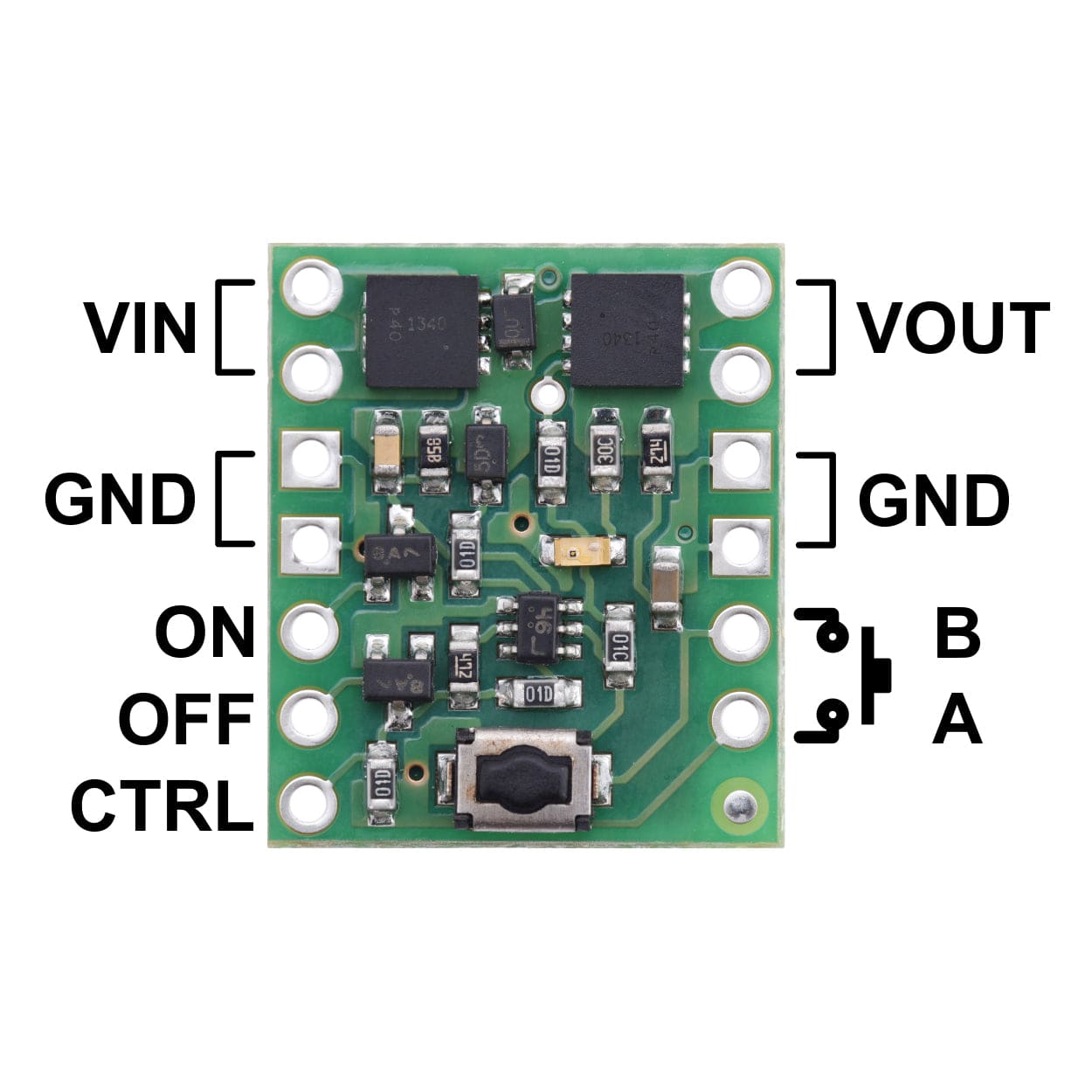
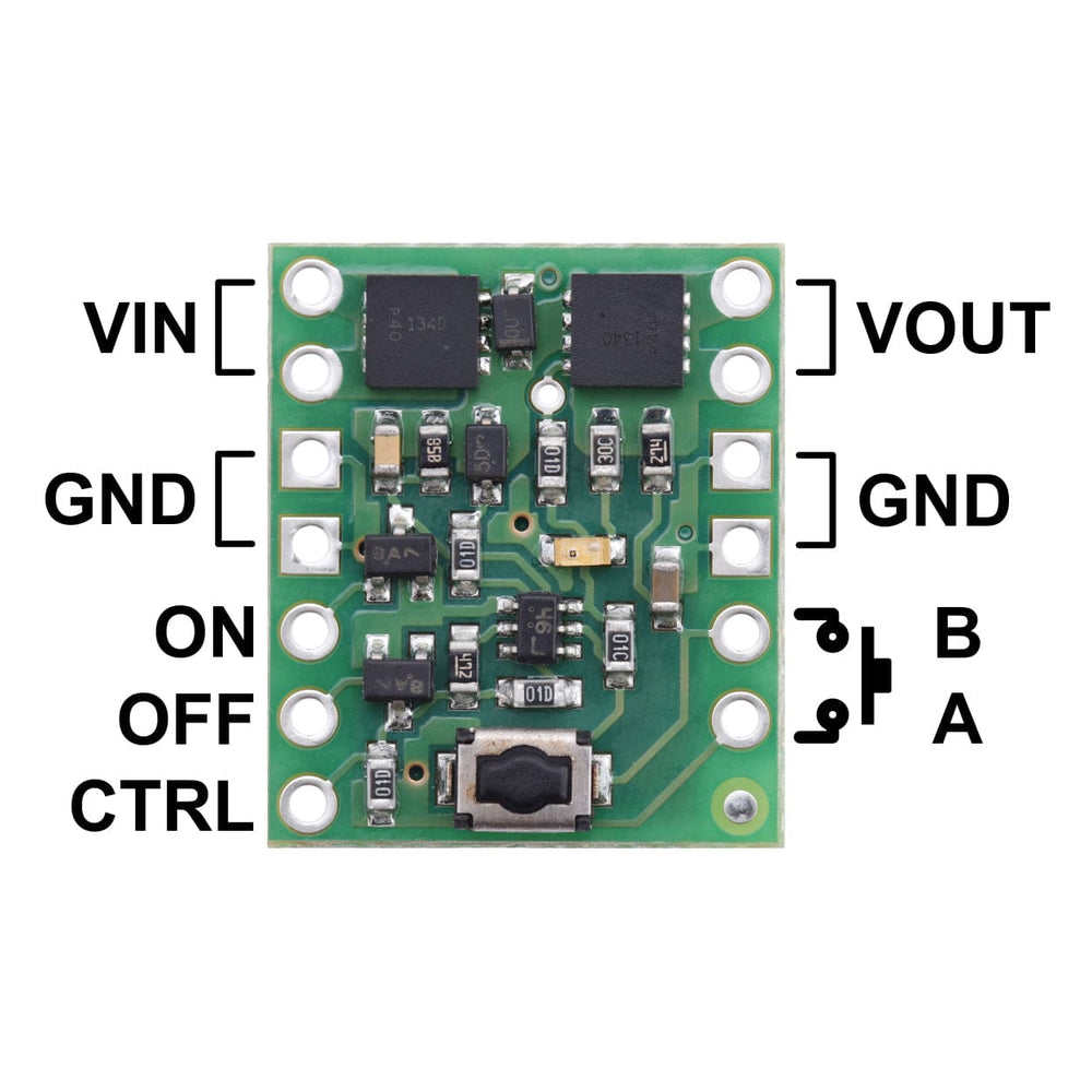
More advanced control options are available through the button connection pins and three control inputs:
| A | Connect through momentary switch to pin “B” for standard push-on/push-off operation. Connect through momentary switch to ground for on-only operation. |
| B | Connect through momentary switch to pin “A” for standard push-on/push-off operation. |
| ON | A high pulse (> 1 V) on this pin turns on the switch. |
| OFF | A high pulse (> 1 V) on this pin turns off the switch (e.g. allowing the target device to shut off its own power). |
| CTRL | This pin directly determines the state of the switch. A high pulse (> 1 V) on this pin turns on the switch; a low pulse (e.g. driving the pin low with a microcontroller output line or pushing a button connected from this pin to ground) turns the switch off. Leave this pin disconnected or floating when not trying to set the switch state. Note that this pin should not be driven high at the same time the “OFF” pin is driven high. |
The ON, OFF, and CTRL pins on the pushbutton power switch do not require a pulse to operate, but leaving any of them in a high state could interfere with the switch’s other control methods, so we generally recommend using pulsed signals with them. The input structures for the three control inputs are shown below:

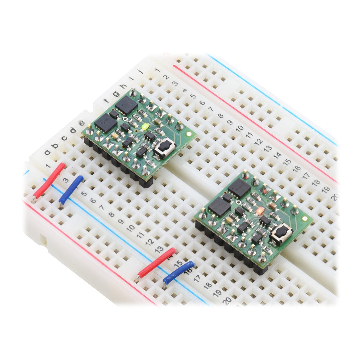
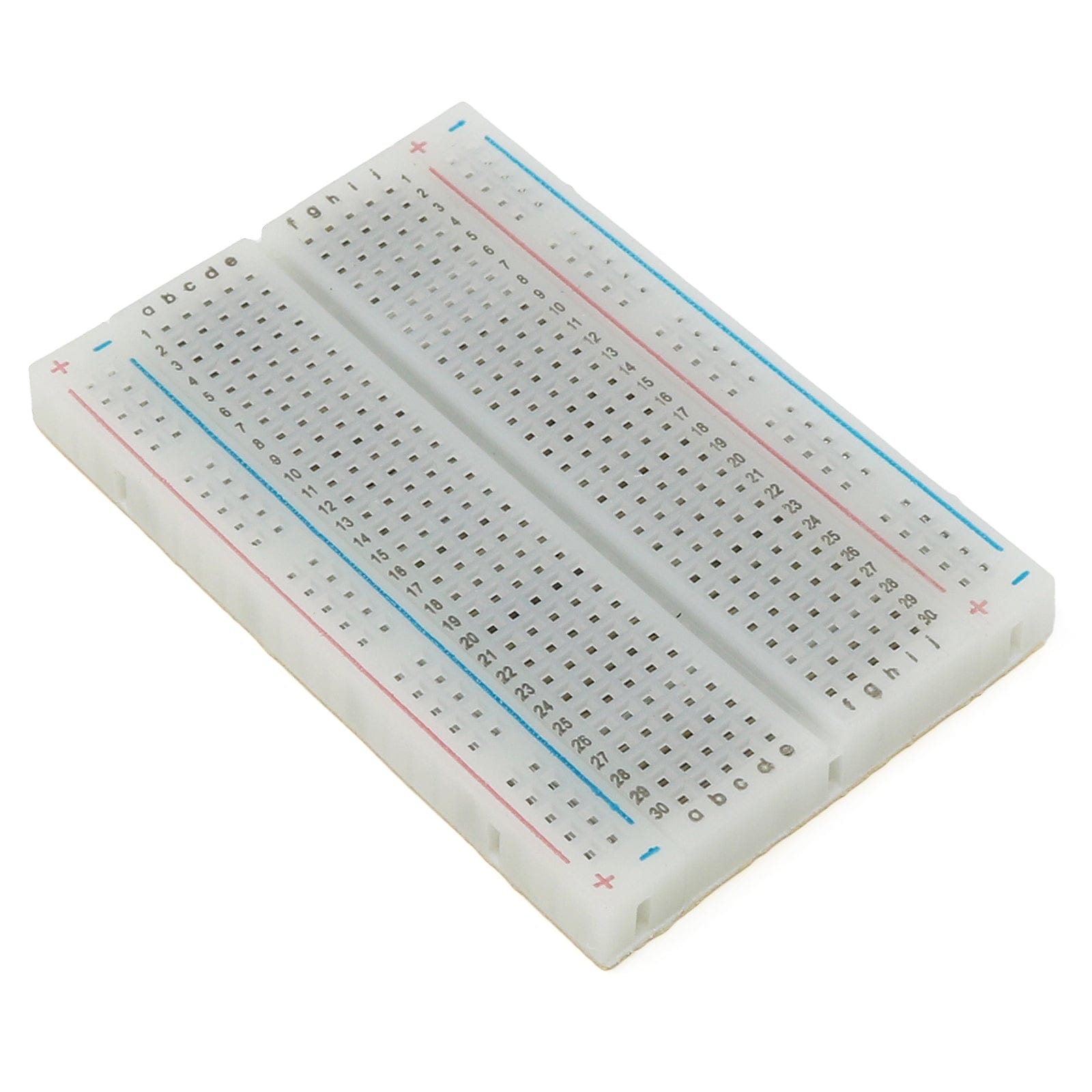
The Pushbutton Power Switch is compatible with solderless breadboards and perforated circuit boards with standard 0.1″ spacing. For such applications, the included male header pins can be soldered to the switch PCB. Alternatively, wires can be soldered directly to the switch PCB for non-breadboard applications. For high-current applications, make sure that the wires can safely carry the current. Two pads/pins are provided for each of the power nodes, and multiple pads should be used for applications drawing over 5A.
Because MOSFETs in the on state are effectively resistive, the power heating the board is proportional to the square of the current flowing through it. The comparison table near the top of this page shows typical currents that heat the MOSFETs to 55°C, where the MOSFETs start being noticeably warm but are still generally safe to touch, and currents that heat the MOSFETs to 150°C, the absolute limit for the MOSFETs. With adequate cooling, or for brief periods if the MOSFETs are not hot to begin with, currents up to the listed maximums are attainable.
Interrupting large currents can cause voltage spikes (positive on the input side and negative on the output side) that depend on the inductance of the power connections and that can exceed the limits of the device. Appropriate measures to limit the size of these spikes include minimising the lengths of wires, placing capacitors at the power switch to smooth the spikes and absorb some of the energy, placing a Schottky diode across the power output to absorb negative spikes, and placing a transient voltage suppressor (TVS) across the power input to absorb positive spikes.
The switch operating range is limited by the ability to change state reliably. At low voltages, the switch is difficult to turn on, and the switch will turn itself off once the voltage falls far enough (this shutoff point can be as high as 4.5V and 2V for the SV and LV versions, respectively). At high voltages, the switches are more likely to turn on when power is initially applied. The reliability of turning off is affected by a combination of the supply voltage, the amount of bouncing on the pushbutton switch, and the amount of noise on the supply line. For applications at the high end of the operating range, tests should be performed to ensure that the device can properly turn off.
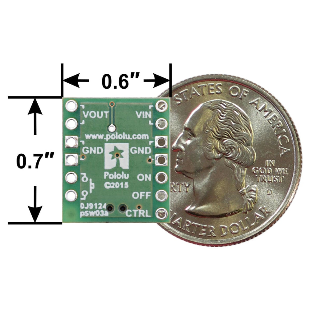
| Size | 0.6″ × 0.7″ × 0.12″1 |
| Weight | 0.6g1 |
| Current rating | 4.3A2 |
| Minimum operating voltage | 4.5V |
| Maximum operating voltage | 40V3 |
| Reverse voltage protection? | Y |
| PCB dev codes | psw03a, psw03c |
| Other PCB markings | 0J9124 |
| LED color | Green |
Your payment information is processed securely. We do not store credit card details nor have access to your credit card information.