Pololu Isolated Solid State Relay/Switch - SPST
Version:60V 7A
Price:
Sale price
£3.80
Stock:
Login / Signup
Cart
Your cart is empty


This solid-state relay/switch board from Pololu provides a way to make and break an electrical connection based on a 2.7V to 40V input signal.
Its electrically isolated output makes it suitable for various applications where mechanical relays are traditionally used, while its semiconductor-based design avoids many of a mechanical relay’s disadvantages.
Two versions of this board are available (select before adding to cart):
Warning: This product can get hot enough to burn you long before the chip overheats. Take care when handling this product and other components connected to it.
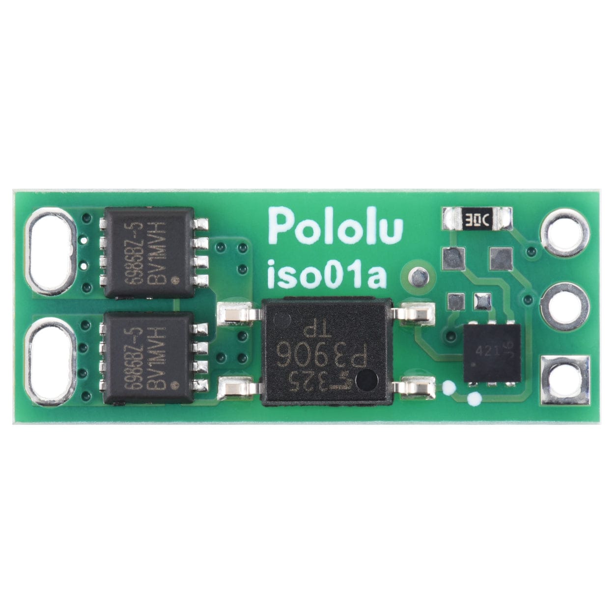
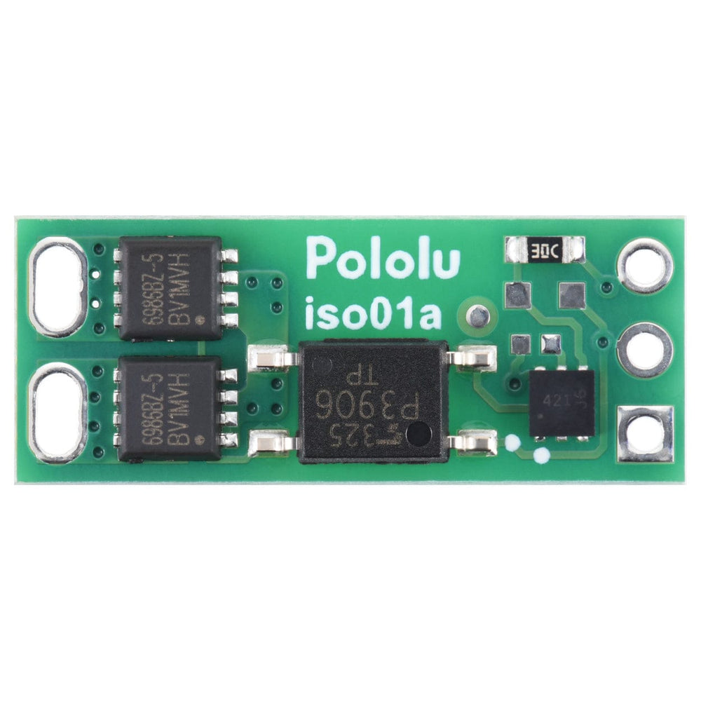
This board functions as a solid-state, single-pole, single-throw (SPST) relay or switch that can be activated by a low-current control signal between 2.7V and 40V. The switching is performed by a pair of MOSFETs controlled by an optically isolated driver that galvanically isolates the load from the control inputs.
The MOSFETs are arranged back-to-back to make the two outputs symmetric and equivalent, allowing bidirectional current control with the switch in any orientation relative to the load (for example, this board can be used for high-side or low-side switching). The board can be used as a replacement for a mechanical relay in many situations, and its solid-state design makes it immune to problems like contact wear and arcing that limit the service life of mechanical relays.
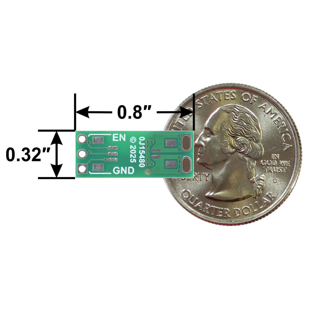
It also offers silent operation and a smaller form factor (0.8″ × 0.32″ × 0.13″) than a typical mechanical relay with a comparable current rating. These devices can also be used for isolating logic signals, but note that the turn-on and turn-off times of the order of 1 ms make them unsuitable for signalling rates beyond a few hundred per second.

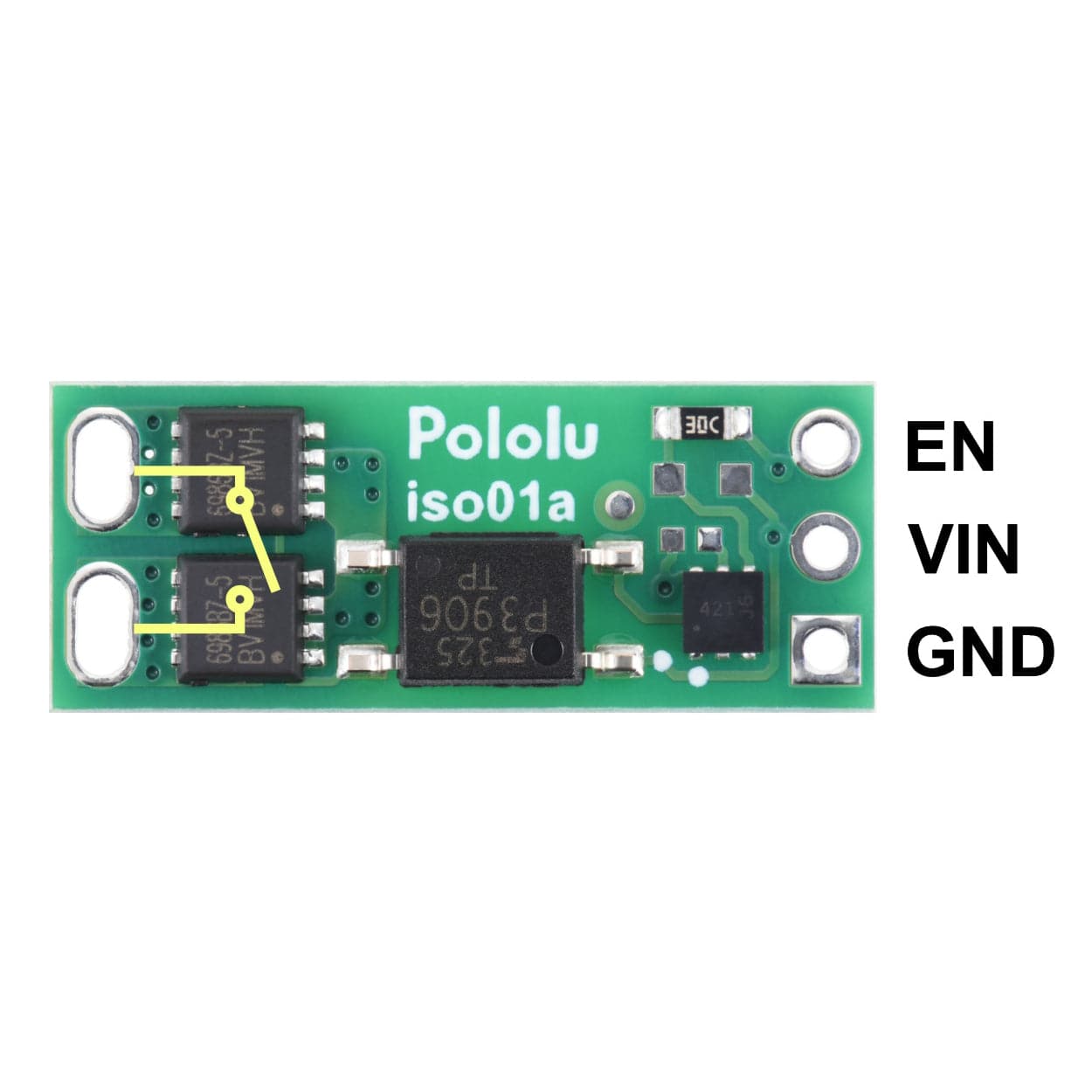
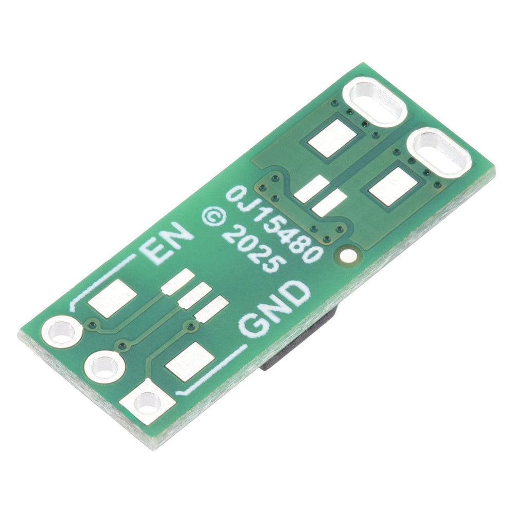
The load connection points are accessible on one side of the board, while the control pins are routed to the other. The control circuit is powered by supplying 2.7 V to 40 V across the VIN and GND pins, and it is activated by a high (2.7 V to 40 V) control signal on the EN pin, which turns on the output MOSFETs. The EN signal turns on the output switch via an LED driver and an optocoupler (or opto-isolator) that provides the board’s electrical isolation. The output switch is made from a pair of back-to-back MOSFETs, so it is symmetric and bidirectional, and this board can be used as a high-side switch or low-side switch.
The board’s control circuit will typically draw up to 10 mA from VIN when EN is high (slightly less at voltages below 20 V). If your EN signal source can provide at least 10 mA, you can tie EN and VIN together—for example, by soldering a short piece of wire between the through-holes—to power and activate the control circuit with a single connection (since the board does not require VIN to be present when EN is low).
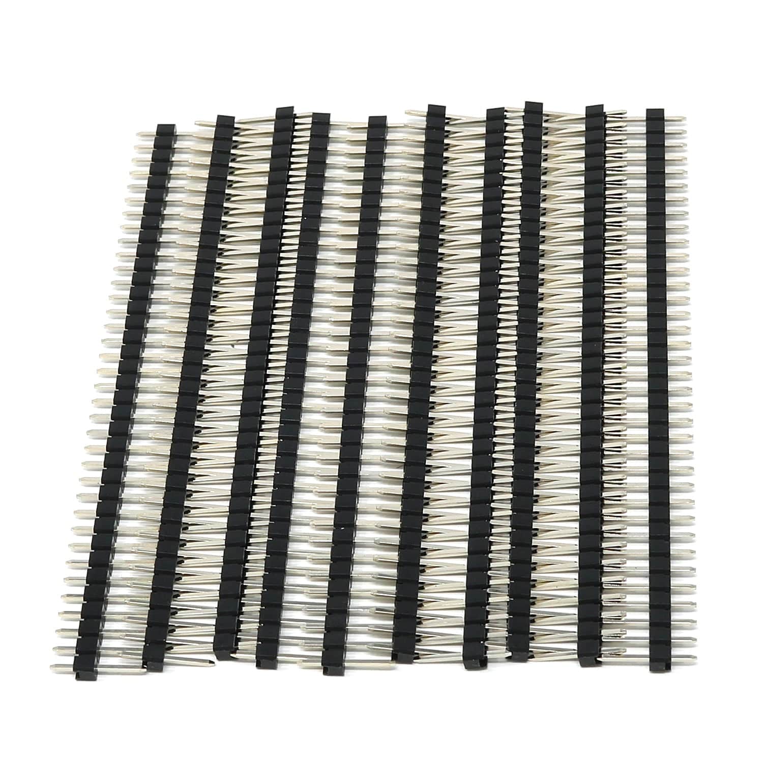
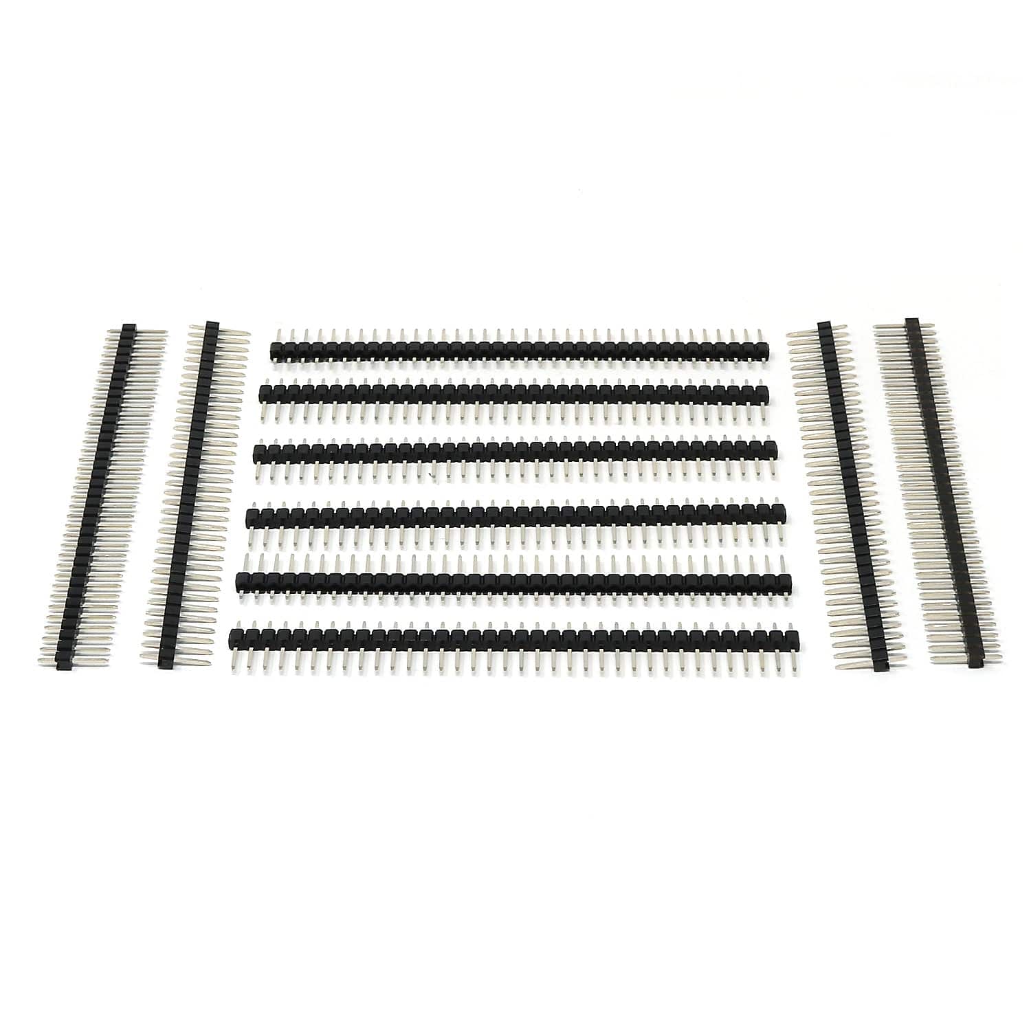
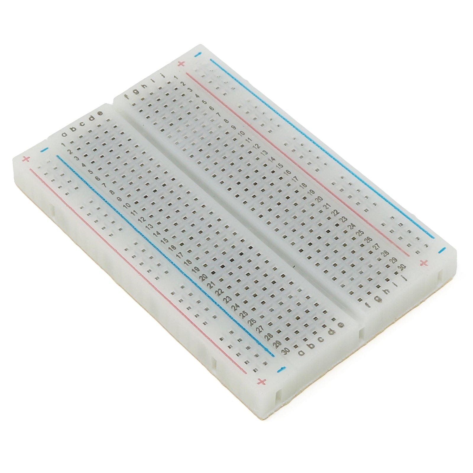
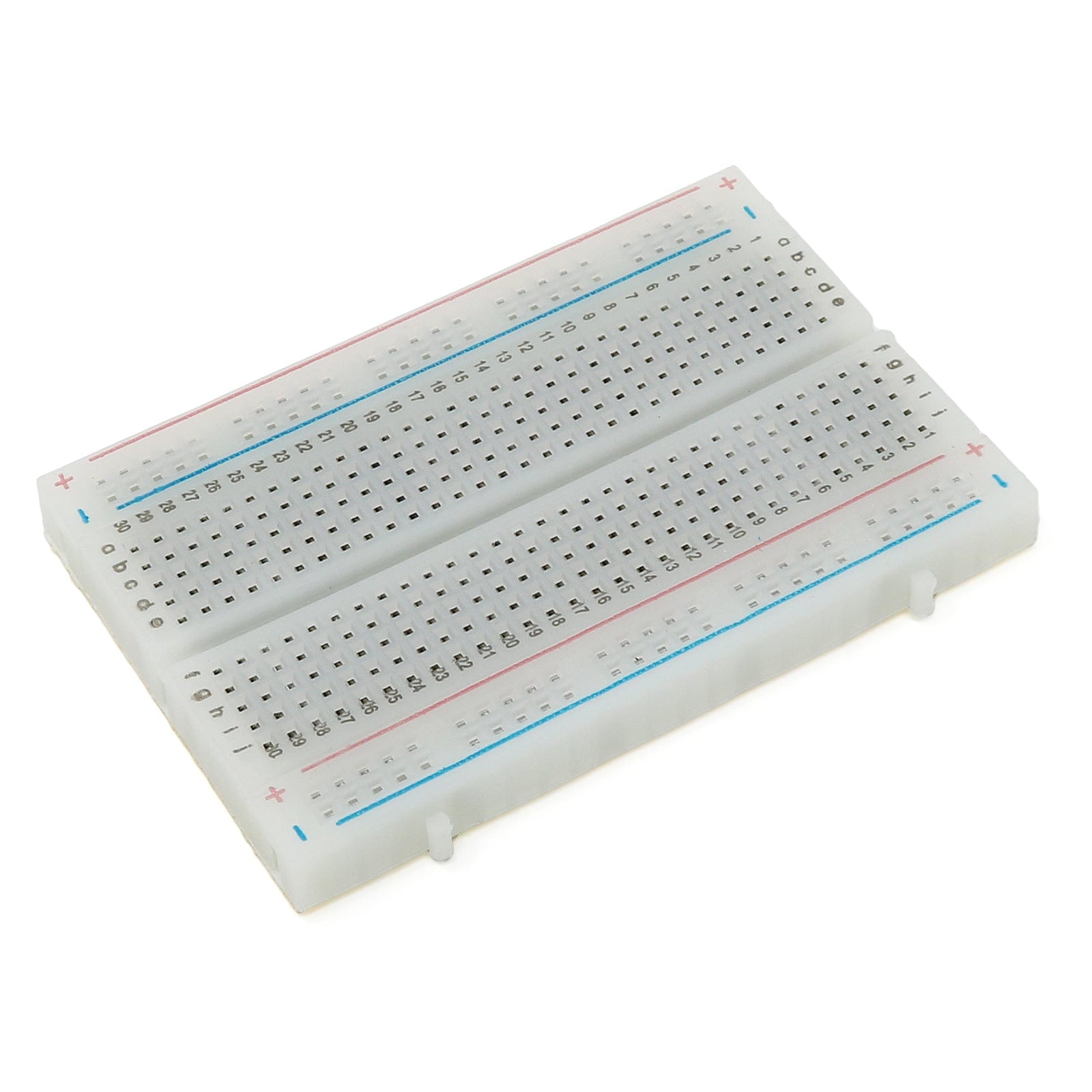
The EN, VIN, and GND pins work with 0.1″-pitch header pins and are compatible with standard solderless breadboards.
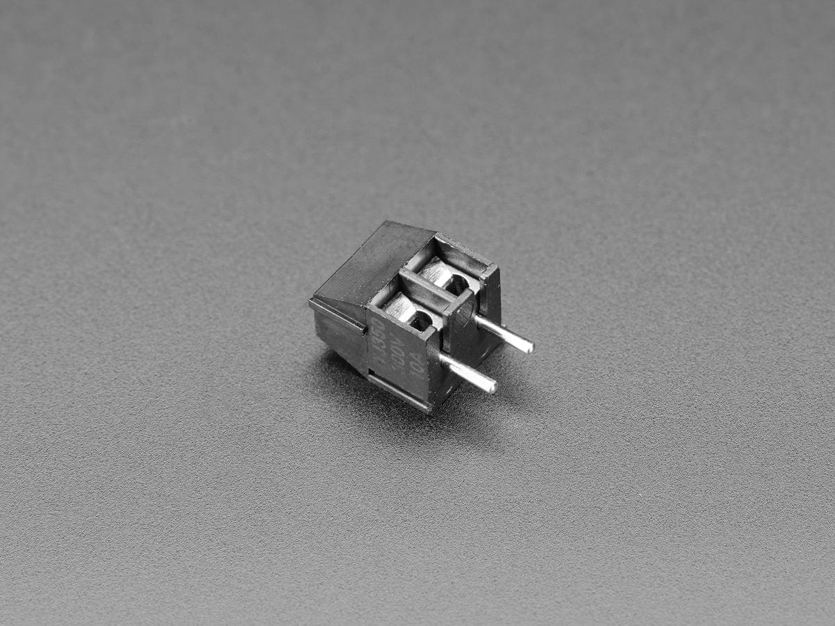
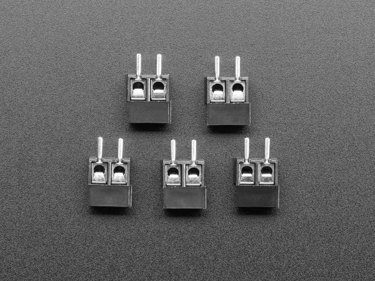
You can connect the board’s output terminals to your circuit in a variety of ways. For typical high-current applications, you can solder wires directly to the 0.045″×0.095″ slots. The slots can also accommodate 3.5mm-pitch and 5mm-pitch terminal blocks as shown below:

The current path slots can also accommodate a 1×2 0.2″-pitch header or a 1×3 0.1″-pitch male header with the middle pin removed (as shown in the pictures below).

In our tests, we found that the 30V version of the relay/switch could conduct about 11A continuously, and the 60V version could conduct about 7A continuously, without reaching the thermal limit for the MOSFETs. Our tests were conducted at approximately 25°C ambient temperature with no forced air flow.
The actual current you can pass through the board will depend on how well you can keep it cool. The printed circuit board is designed to help with this by drawing heat out of the MOSFETs. Solid connections to the output pins (such as with thick soldered wires) can also help reduce heat build-up in the MOSFETs and board.
Warning: Exceeding temperature or current limits can cause permanent damage to the MOSFETs. If you are switching an average continuous current greater than about 2/3 of the specified maximum, we strongly recommend that you monitor the MOSFETs’ temperature and look into additional cooling if necessary.
Warning: This product can get hot enough to burn you long before the chip overheats. Take care when handling this product and other components connected to it.
This product is not designed to or certified for any particular high-voltage safety standard. The PCB traces are laid out to provide at least 4.8 mm of creepage between the control side and the load side. A rough rule of thumb is that uncontaminated FR4 PCBs should have approximately 1 mm of creepage per 100 VRMS of isolation. Note that this guideline implies a maximum safe voltage lower than the maximum isolation voltage rating of 3.75 kVRMS for the TLP3906 optocoupler used on this board.
Warning: This product is generally intended for use below 30V, and many of the application example pictures (e.g. use on a breadboard) are appropriate for such lower-voltage applications. These boards can be used at higher voltages, but working with higher voltages can be extremely dangerous and should only be attempted by qualified individuals with appropriate equipment and experience.
| Version | 60V 7A | 30V 11A |
| Size | 0.8″ × 0.32″ × 0.13″ | |
| Weight | 0.4g | |
| Minimum control voltage | 2.7V | |
| Maximum control voltage | 40V | |
| Maximum input current | 10mA1 | |
| Maximum load voltage | 60V | 30V |
| Maximum load current | 7A | 11A |
| Maximum on resistance | 30mΩ | 10mΩ |
| Maximum turn-on time | 1ms | 1.5ms |
| Maximum turn-off time | 1ms | |
| PCB dev codes | iso01a | |
| Other PCB markings | 0J15480 | |
Your payment information is processed securely. We do not store credit card details nor have access to your credit card information.