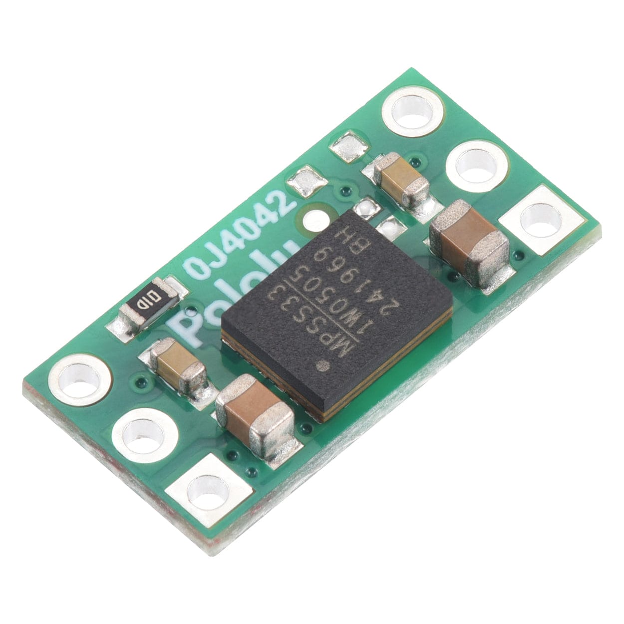
Pololu Isolated DC-DC Power Module (5V/3.3V 200mA)
Price:
Sale price
£5.80
Stock:
Quantity:
Login / Signup
Cart
Your cart is empty

This Pololu DC-DC power module provides galvanically isolated (electrically isolated) and regulated 5V or 3.3V power at up to 200 mA, as follows:
| Input voltage | Output voltage | Max output current |
| 4.5 V to 5.5 V | 5 V (default) or 3.3 V (selectable) | 200 mA |
| 3 V to 3.6 V | 3.3 V | 75 mA |
Unlike non-isolated regulators, the output ground (GND2) is effectively independent of the input side, which can be useful for preventing ground loops and avoiding ground currents that can cause unpredictable system behavior or even lead to destruction.
This module is based on the MPS MIE1W0505BGLVH, which has a 2.5 kVRMS isolation rating; the PCB is designed with the same 3.5 mm minimum clearance and creepage between the isolated sides as the IC, but please note that the module itself is not certified to any standard. See the MIE1W0505BGLVH datasheet for more information.

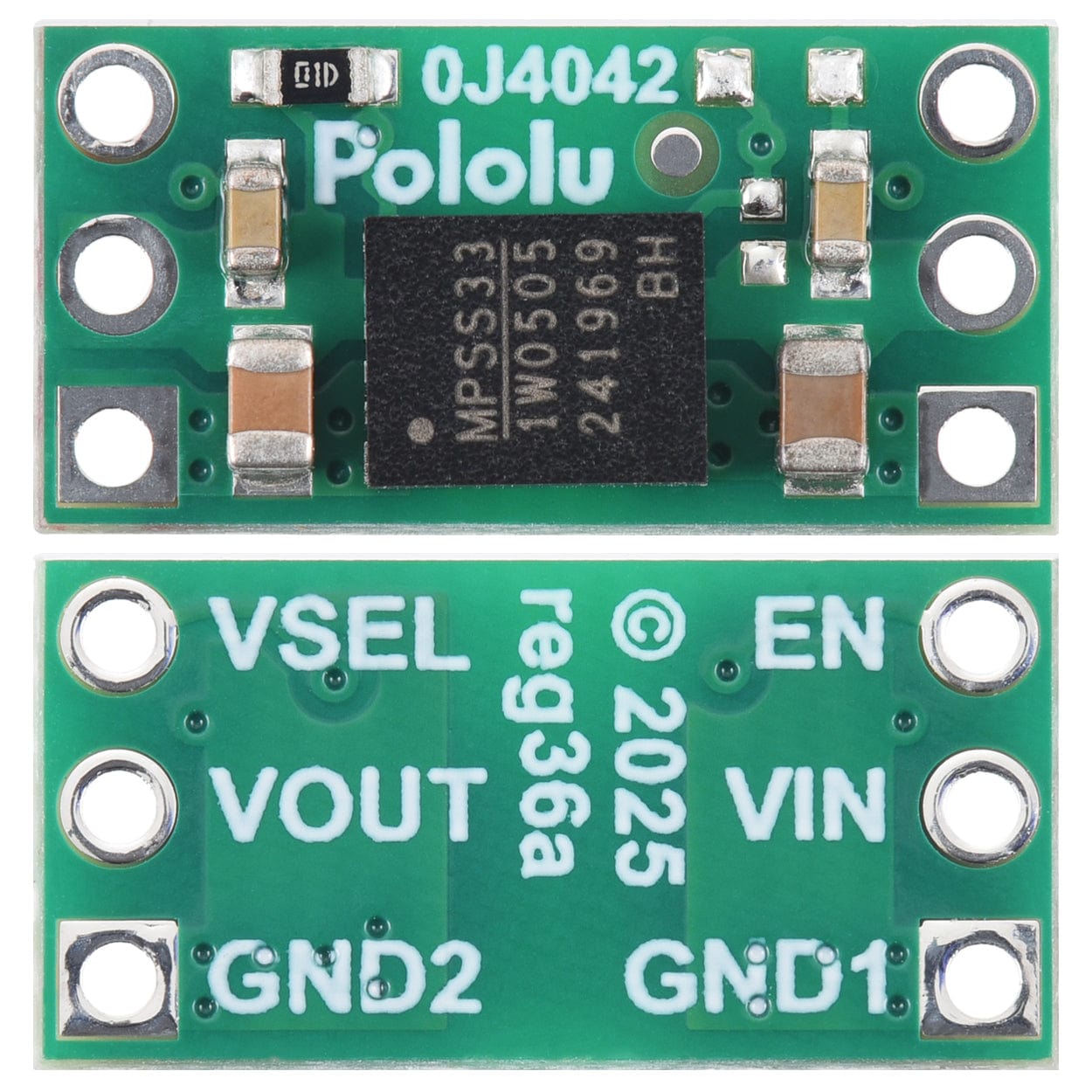
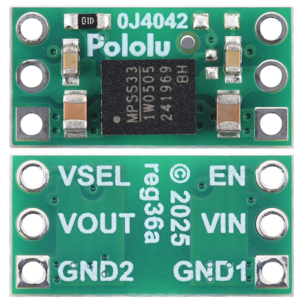
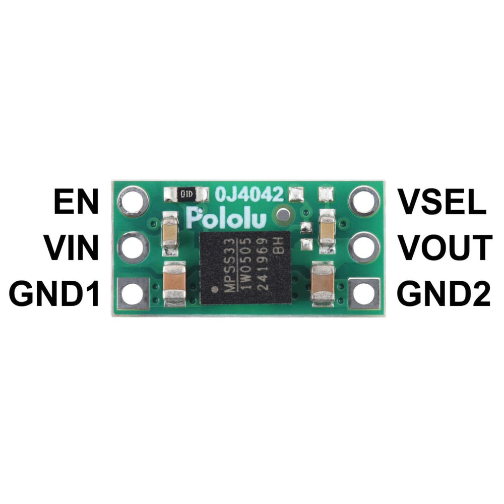
Input power is supplied across VIN and GND1 and output power is delivered across VOUT and GND2. The two sides are galvanically isolated (GND1 is NOT connected to GND2). Note that the efficiency of this regulator is less than 50%, so the input power will need to be at least twice the output power.
| VIN range | VSEL | VOUT | Output current |
| 4.5 V to 5.5 V | NC (default) | 5 V | 180 mA continuous, 200 mA peak |
| GND2 | 3.3 V | ||
| 3 V to 3.6 V | GND2 | 3.3 V | 75 mA continuous |
The enable input, EN, is pulled up to VIN through a 100 kΩ resistor, which enables the regulator by default. This pin can be driven low to put the device into a low-power state where the shutdown current draw is typically dominated by the current through the pull-up resistor (10 µA per volt on VIN).
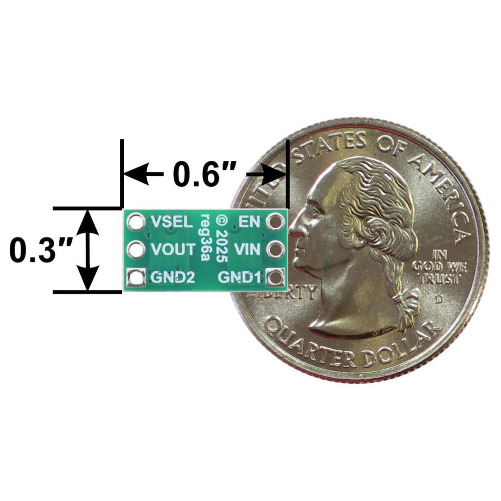
The output voltage selection pin, VSEL, is floating, which sets the output voltage to 5 V by default. To select 3.3 V for the output voltage, connect VSEL to GND2. This can be done using the board’s through-holes or by adding an SMT jumper to the pads circled in the picture below. Note: Do not change VSEL while the regulator is powered.

| Minimum operating voltage | 3.0 V |
| Maximum operating voltage | 5.5 V |
| Maximum output current | 200 mA |
| Output voltage | 5 V |
| Reverse voltage protection? | N |
| Maximum quiescent current | 8 mA |
| Size | 0.3″ × 0.6″ × 0.1″ |
| Weight | 0.5 g |
Your payment information is processed securely. We do not store credit card details nor have access to your credit card information.