Pololu Ideal Diode Reverse Voltage Protector (4-60V 25A)
Price:
Sale price
£8.20
Stock:
Quantity:
Login / Signup
Cart
Your cart is empty


This Pololu module protects a connected load from reverse voltages down to -60 V. This version acts as an ideal diode, blocking reverse current from output to input.
| Operating voltage | Max current | Resistance | Reverse current blocking |
| 4 V – 60 V | 25 A | < 1.5 mΩ | yes (ideal diode) |
Pololu Reverse Voltage Protectors are compact modules that can be inserted between a power supply and its load to protect that load from damage in the case of accidental reversal of power polarity. They operate from 4V (3.2V after startup) to 60V and provide protection from negative voltages down to -60V.
We also stock a version without reverse current blocking.
Note: Any voltage on the output will reduce the 60V maximum rating. For example, if there is a large capacitor charged to 24V on the output, the minimum negative voltage would be -36V.
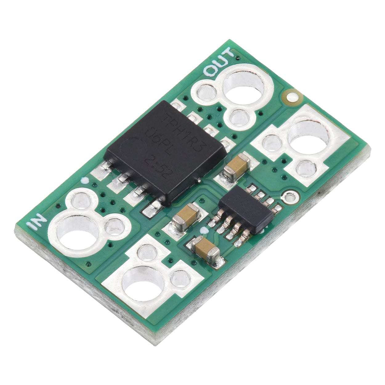
This specific module uses an LM74700-Q1 reverse voltage protection ideal diode controller and N-channel MOSFET to provide protection from negative voltages down to -60V.
It operates from 4V (3.2V after startup) to 60V and has a VIN path impedance of approximately 1.5mΩ when the MOSFET is on (i.e. when power is connected with the proper polarity), enabling currents up to around 25A continuous (and up to around 50A for a few seconds). This version acts as an ideal diode, blocking reverse current from output to input.

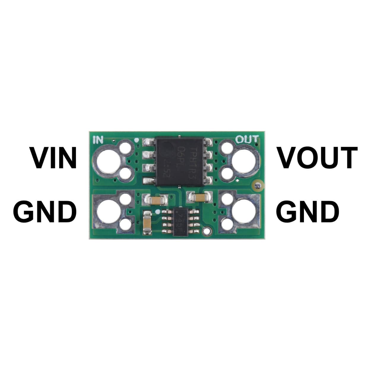
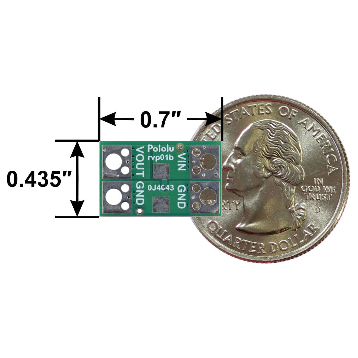
Supply power and ground connect to the VIN and GND side of the board, and the VOUT and GND pins connect to the load. If the supply is connected correctly, with its positive voltage on VIN, the power will pass through the board to VOUT. If the supply is connected incorrectly, with the positive voltage on GND, supply power will not pass through to the output, and any connected load will be protected from the reversed supply voltage.
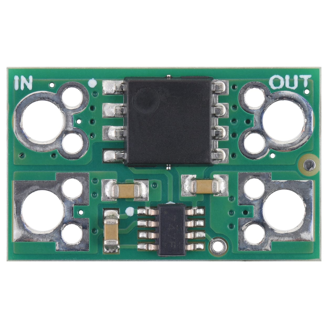
The larger input and output through-holes can accommodate 5mm-pitch terminal blocks or up to 14 AWG wires, and the smaller through-holes are spaced for 0.1″-pitch headers.
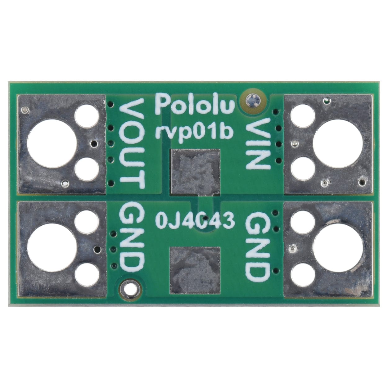
There are pads for adding an optional SMB-size transient voltage suppressor (TVS) across VIN and GND on the bottom side of the board:

| Minimum operating voltage | 4V |
| Maximum operating voltage | 60V |
| Maximum current | 25A |
| Reverse current blocking | Y |
| Size | 0.435″ × 0.7″ × 0.11″ |
| Weight | 0.7 g |
Your payment information is processed securely. We do not store credit card details nor have access to your credit card information.