Pololu Dual G2 High-Power Motor Driver 24v18 Shield for Arduino
Price:
Sale price
£100.80
Stock:
Quantity:
Login / Signup
Cart
Your cart is empty

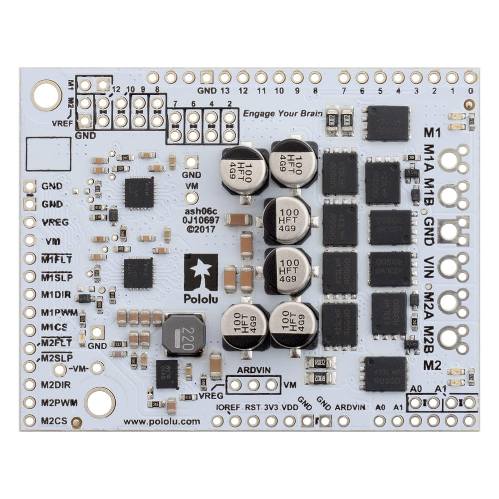

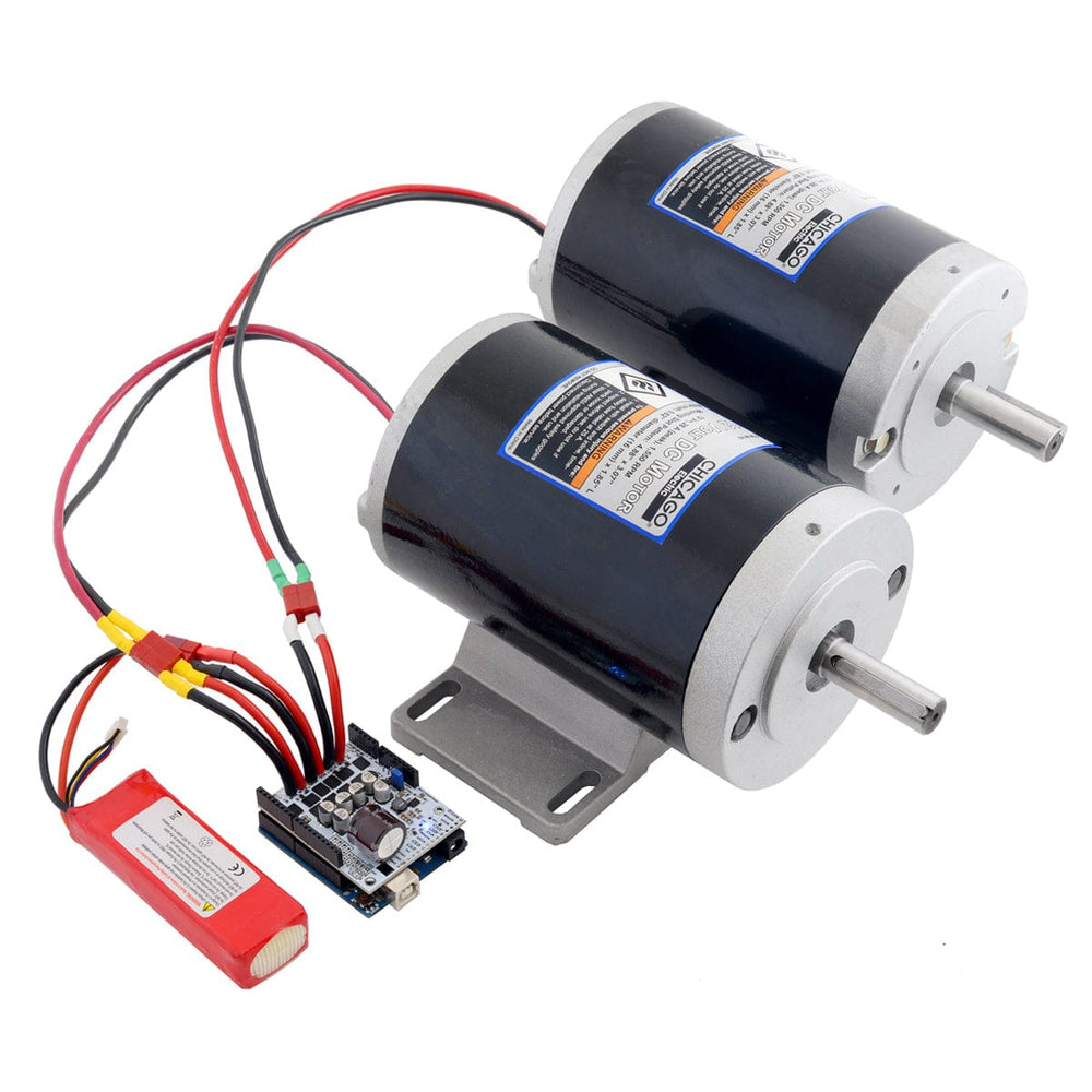

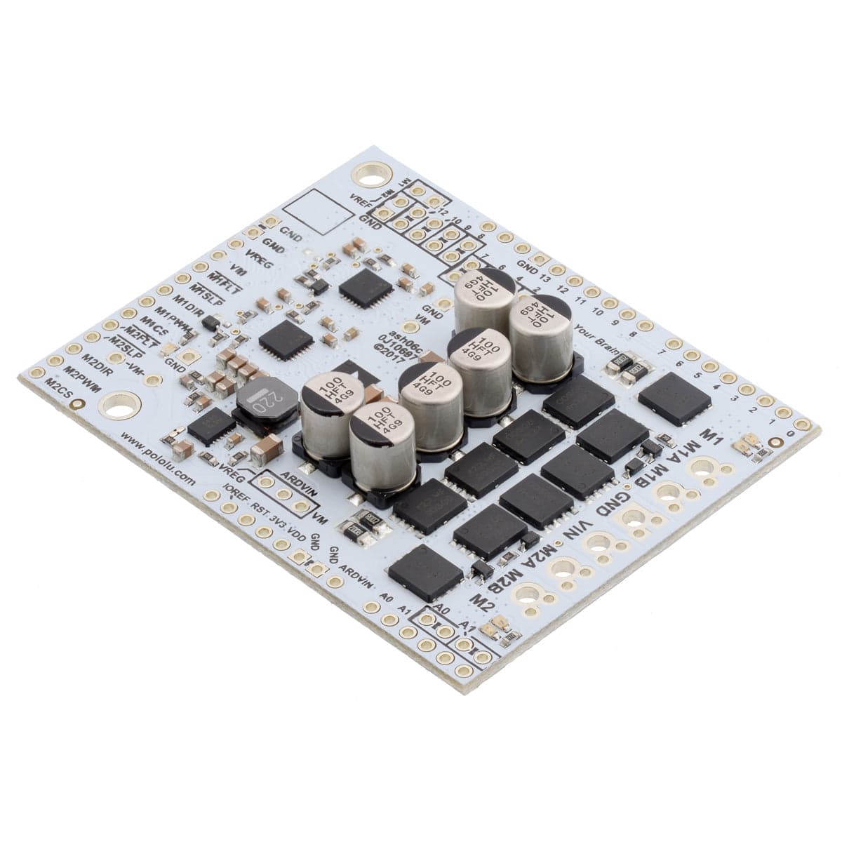
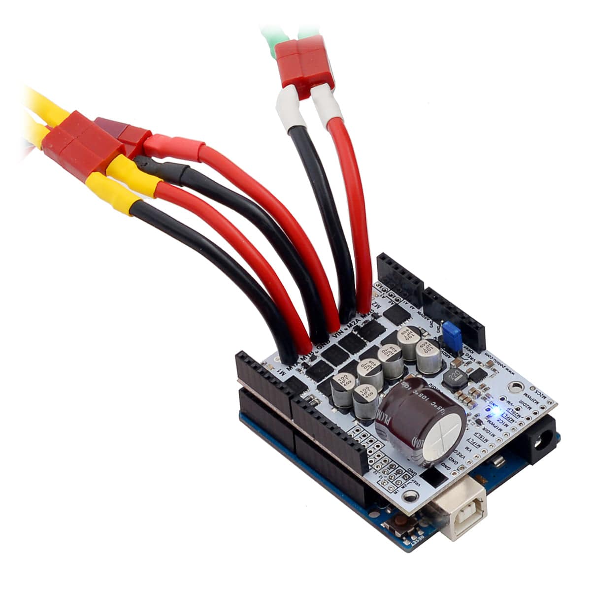
This shield from Pololu makes it easy to control two high-power DC motors with your Arduino or Arduino-compatible board. Its twin discrete MOSFET H-bridges support a wide 6.5V to 40V operating range and are efficient enough to deliver a continuous 18A without a heat sink.
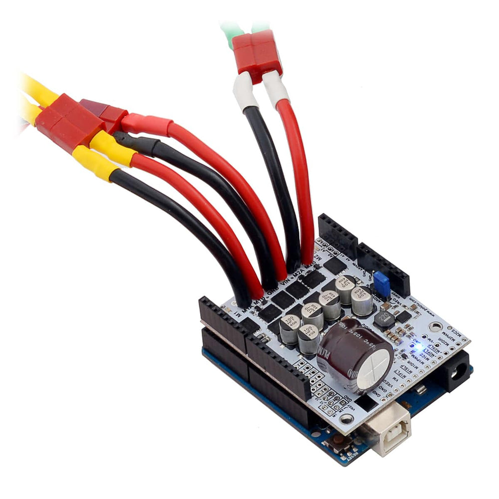
The drivers offer basic current sensing and current limiting functionality, and they accept ultrasonic PWM frequencies for quieter operation. The Arduino pin mappings can all be customized if the defaults are not convenient, and the motor driver control lines are broken out along the left side of the shield for general-purpose use without an Arduino.
Warning: This motor driver has no over-temperature shut-off. An over-temperature or over-current condition can cause permanent damage to the motor driver. You might consider using either the driver’s integrated current sense output or an external current sensor to monitor your current draw.
This product can get hot enough to burn under normal operating conditions. Take care when handling this product and other components connected to it.
The G2 family of dual high-power motor driver shields features pairs of discrete MOSFET H-bridges designed to drive two large brushed DC motors.
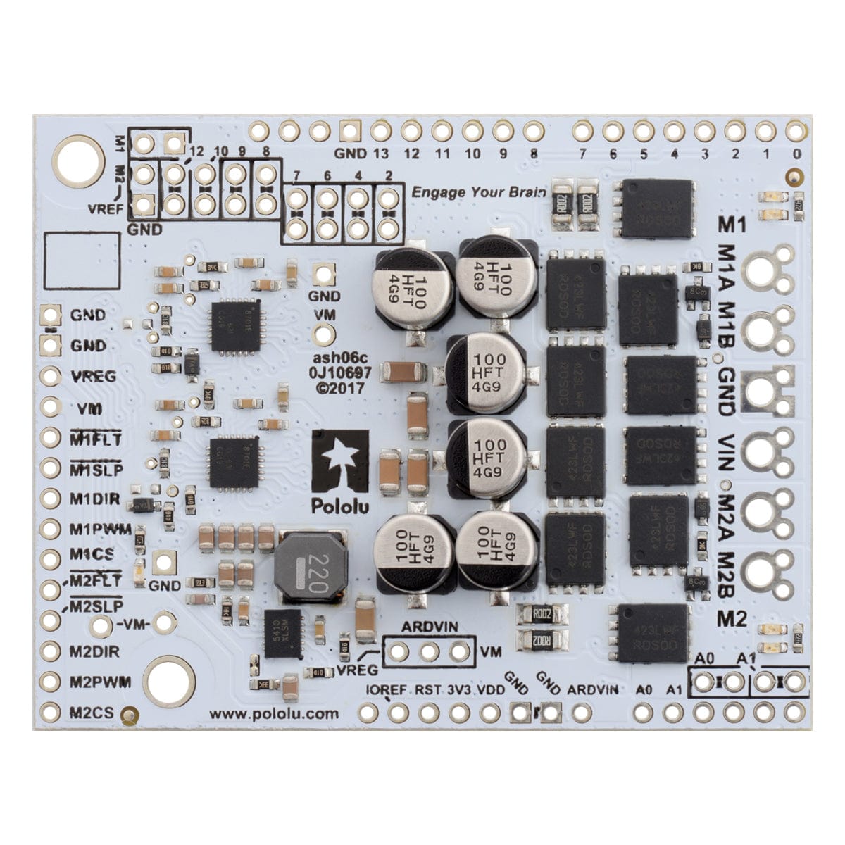
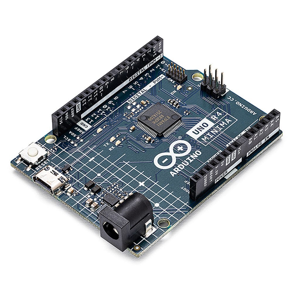
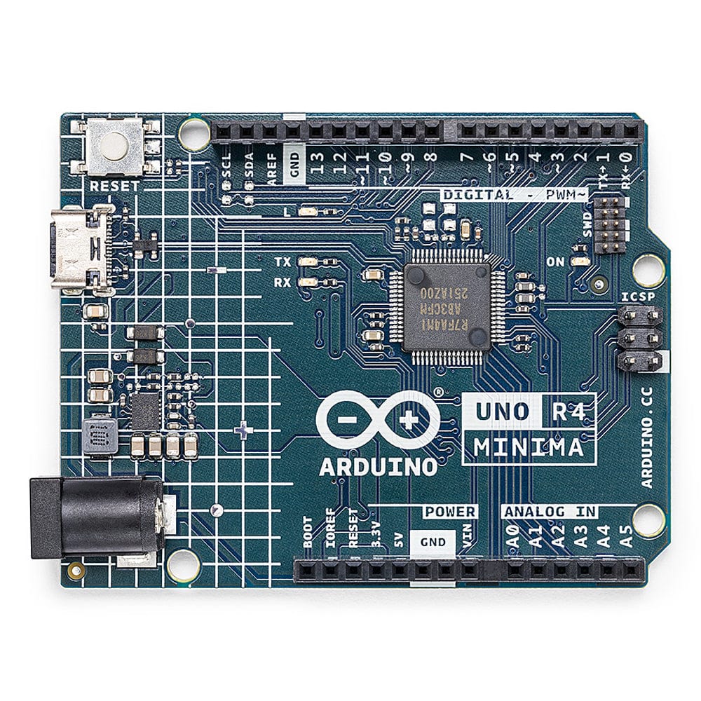
They have the form factor of an Arduino shield, so they can plug directly into an Arduino or compatible board, but they also break out all of the motor driver pins along the left side of the board to enable use as a general-purpose motor driver without an Arduino.
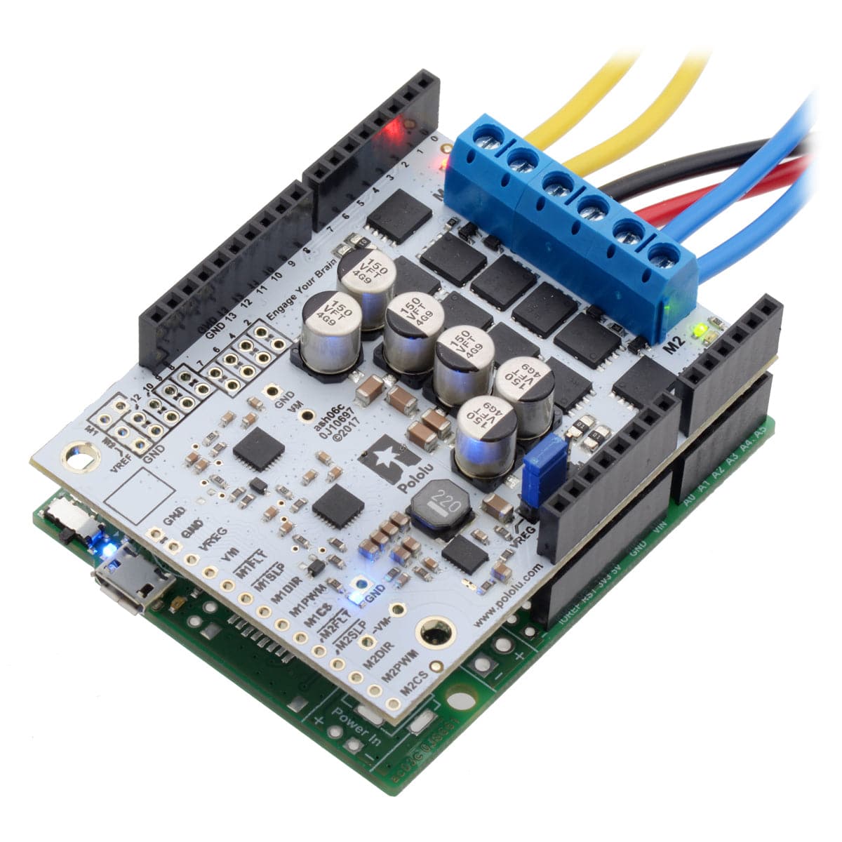
The minimum operating voltage is 6.5V. The maximum operating voltages can be found in the specification table; they are well above what typical Arduinos can tolerate, so the shield included an integrated 7.5V, 1A switching step-down regulator that can optionally be used to power whatever Arduino or Arduino-compatible board it is plugged into, enabling operation from a single power supply. This regulator can also be configured to output 5V for applications where that would be more useful than the default 7.5V, and the Arduino pin mappings can all be customized if the defaults are not convenient.
| Motor channels | 2 |
| Minimum operating voltage | 6.5V |
| Maximum operating voltage | 40V |
| Continuous output current per channel | 18A |
| Current sense | 0.020 V/A |
| Maximum PWM frequency | 100 kHz |
| Minimum logic voltage | 1.8V |
| Maximum logic voltage | 5.5V |
| Reverse voltage protection? | Y |
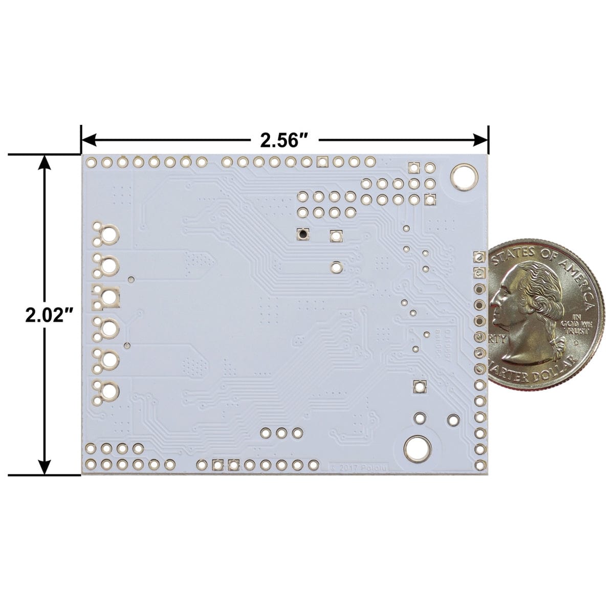
| Size | 2.56″ × 2.02″ × 0.38″ |
| Weight | 19g |
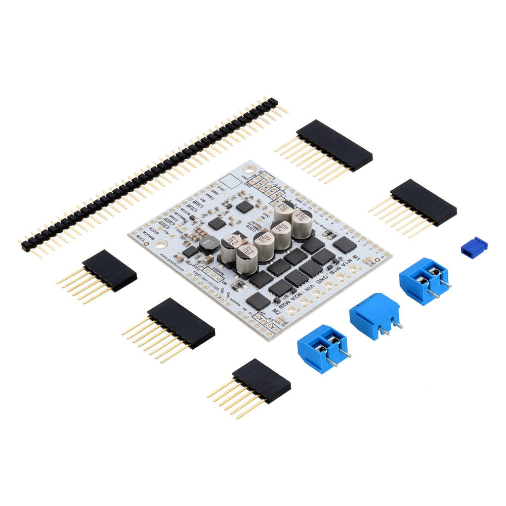
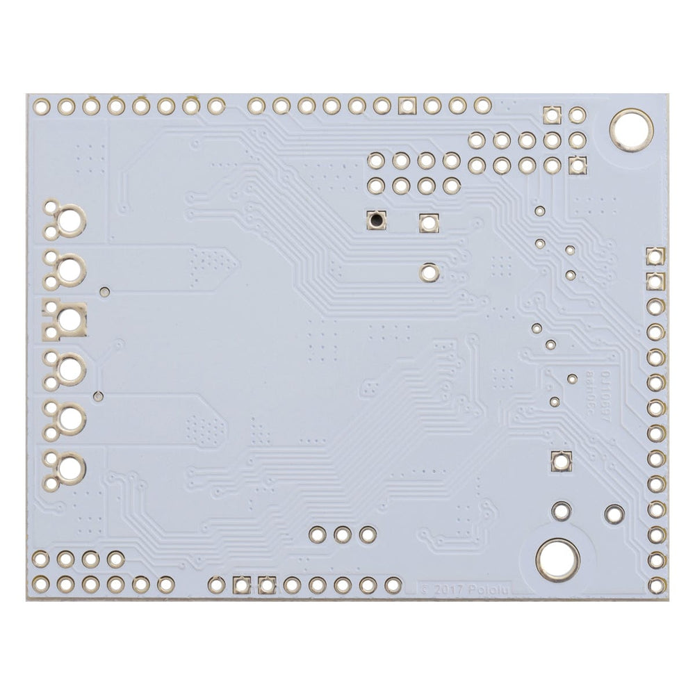
This motor driver board ships with all of the surface-mount parts populated. However, soldering is required for assembly of the included through-hole parts. The following through-hole parts are included:
You can solder the terminal blocks to the six large through-holes to make your motor and motor power connections, or you can break off a 1×12 section of the 0.1″ header strip and solder it into the smaller through-holes that border these larger holes. Note, however, that the terminal blocks are only rated for 16 A, and each header pin pair is only rated for a combined 6 A, so for higher-power applications, thick wires should be soldered directly to the board, and appropriately high-current connectors should be used.
When not using this board as an Arduino shield, you can solder the 0.1″ headers to the logic connections along the left side of the board to enable use with custom cables or solderless breadboards, or you can solder wires directly to the board for more compact installations. Note that motor and motor power connections should not be made through a breadboard.
The motor driver includes six 100 µF or 150 µF electrolytic power capacitors, and there is room to add additional capacitors (e.g. to compensate for long power wires or increase the stability of the power supply). Additional power capacitors are usually not necessary, and no additional capacitors are included with this motor driver.
The two mounting holes are intended for use with #4 screws (not included).
The driver’s current sense pins, M1CS and M2CS, output voltages proportional to the motor currents while the H-bridge is driving. The output voltage is about 10 mV/A for the 18v22 version and 20 mV/A for the other versions, plus a small offset, which is typically about 50 mV.
The driver has the ability to limit the motor current through current chopping: once the motor drive current reaches a set threshold, the driver goes into brake mode (slow decay) for about 25 µs before applying power to drive the motor again. This makes it more practical to use the driver with a motor that might only draw a few amps while running but can draw many times that amount (tens of amps) when starting. You can lower the default current limit threshold by connecting an additional resistor between the VREF pin and the adjacent GND pin.
See the user’s guide for more information on current sense feedback and current limiting.
The MOSFETs can handle large current spikes for short durations (e.g. 100 A for a few milliseconds), and the driver’s current chopping will keep the average current under the set limit. The peak ratings are for quick transients (e.g. when a motor is first turned on), and the continuous rating is dependent on various conditions, such as the ambient temperature.
PWMing the motor will introduce additional heating proportional to the frequency. The actual current you can deliver will depend on how well you can keep the motor driver cool. The driver’s printed circuit board is designed to draw heat out of the MOSFETs, but performance can be improved by adding a heat sink or air flow. For high-current installations, the motor and power supply wires should also be soldered directly instead of going through the supplied terminal blocks, which are rated for up to 16 A.
Warning: This motor driver has no over-temperature shut-off. An over-temperature or over-current condition can cause permanent damage to the motor driver. You might consider using either the driver’s integrated current sense output or an external current sensor to monitor your current draw.
This product can get hot enough to burn under normal operating conditions. Take care when handling this product and other components connected to it.
Your payment information is processed securely. We do not store credit card details nor have access to your credit card information.