Pololu DRV8835 Dual Motor Driver Shield for Arduino
Price:
Sale price
£11.50
Stock:
Quantity:
Cart
Your cart is empty

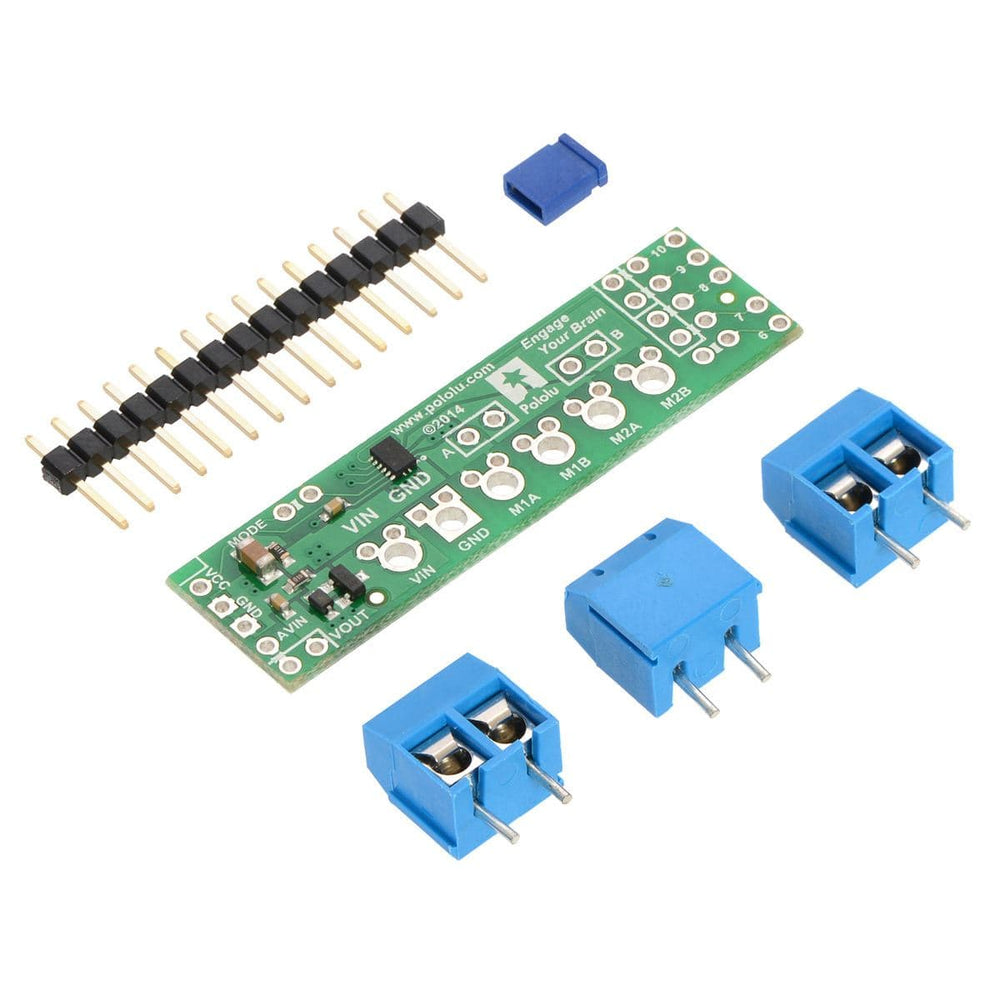


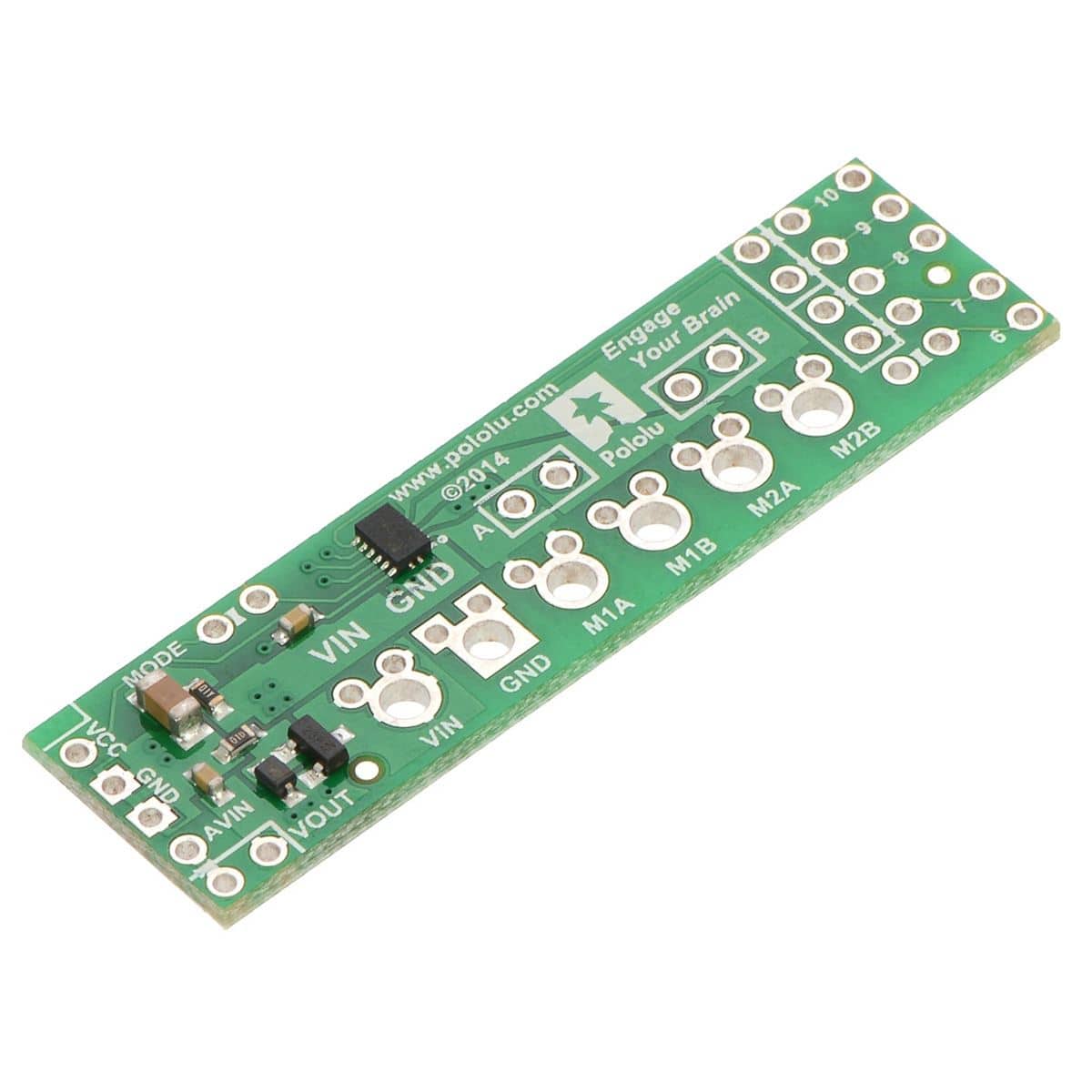
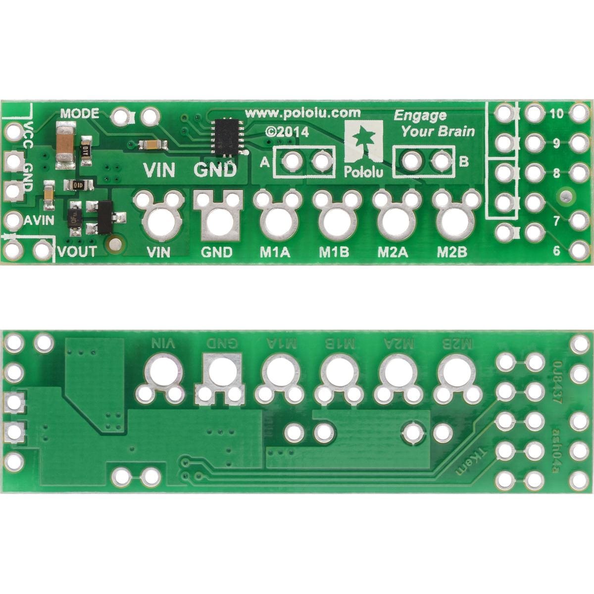
The shield can deliver a continuous 1.2 A per channel and tolerate peak currents up to 1.5 A per channel for a few seconds, and the channels can be optionally configured to run in parallel to deliver twice the current to a single motor. The shield ships fully populated with its SMD components, including the DRV8835 driver and a FET for reverse battery protection; header pins for interfacing with an Arduino and terminal blocks for connecting motors and power are included but are not soldered in.
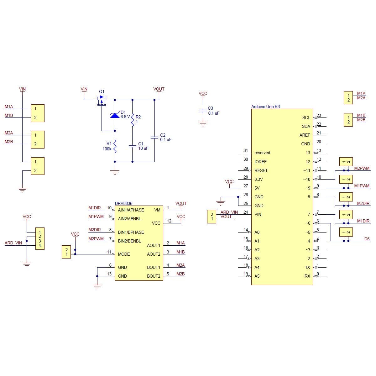
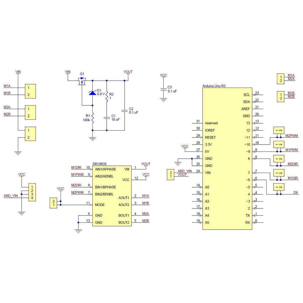
The shield uses digital pins 7, 8, 9, and 10 for its control lines, though the control pin mappings can be customized if the defaults are not convenient. It should be compatible with any board that has a standard Arduino pin arrangement and the ability to generate PWM signals on pins 9 and 10.
This shield is intended to provide a low-cost, basic motor driver option for Arduinos, so it is much smaller than typical Arduino shields and does not include pass-through, stackable headers.
Note: Although the DRV8835 itself works with a minimum motor supply voltage of 0 V, this shield’s reverse-protection circuit limits the minimum to 1.5 V.
This product can get hot enough to burn you long before the chip overheats. Take care when handling this product and other components connected to it.
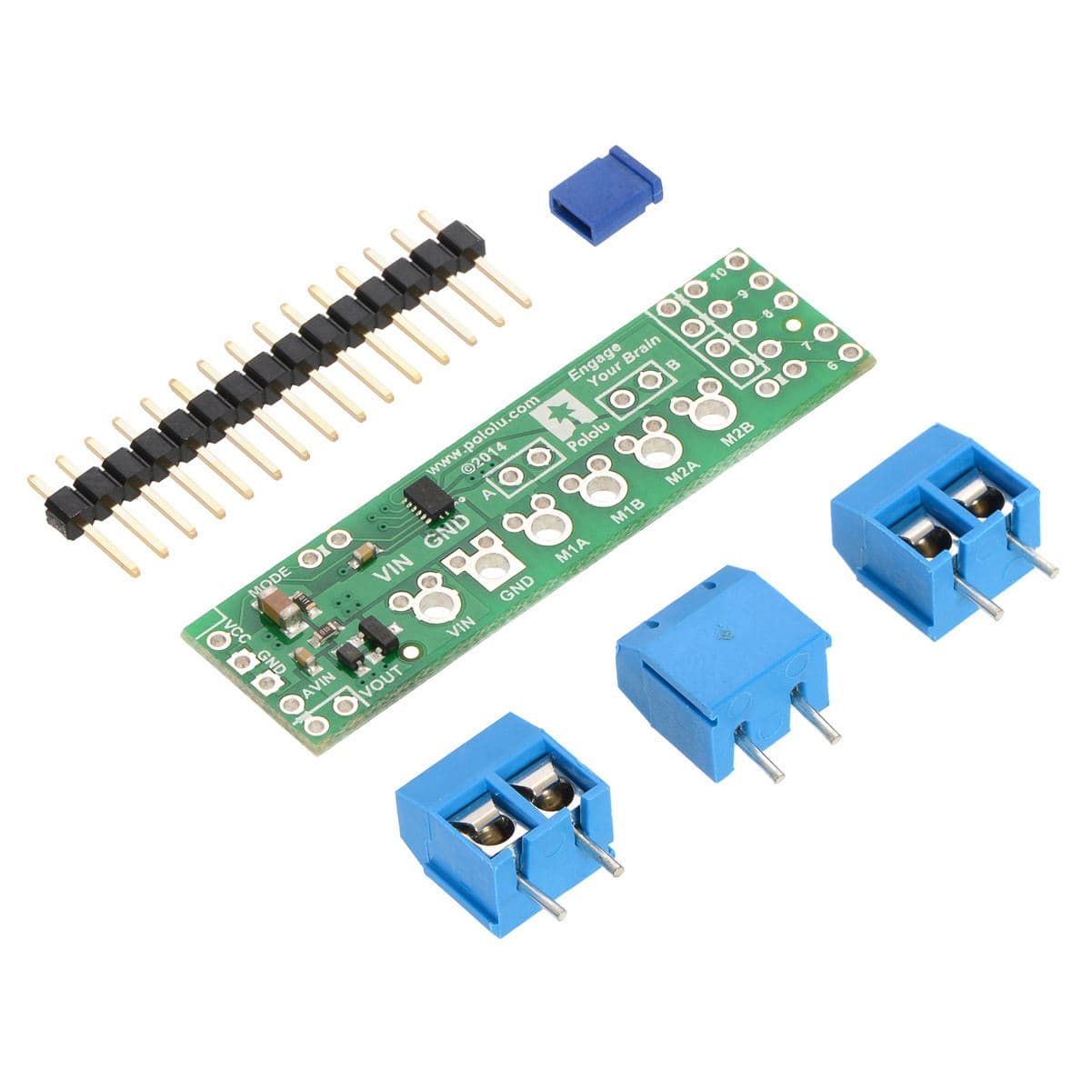
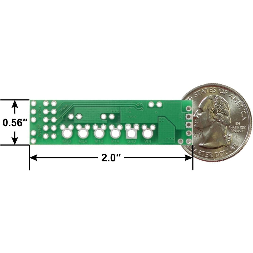
Before the shield can be plugged into your Arduino, header pins must be mounted to the bottom of the board (the side without any components or text) by soldering them into the appropriate holes. The shield ships with a 15-pin 0.1″ straight breakaway male header strip that can be broken into smaller pieces and used for this purpose.
Four holes along the left side of the board (VCC, GND, GND, and AVIN) and all five holes along the right side of the board (digital pins 6 – 10) should be assembled with male header pins so that the shield will make the appropriate connections to the Arduino. Once assembled, one easy way to ensure that you are plugging the shield properly into the Arduino is to align the gap between pins 7 and 8 on the shield with the gap between pins 7 and 8 on the Arduino’s female headers.
If you want the option of powering the Arduino from the shield, you can solder two male header pins to the lower-left corner of the board (in the silkscreen box next to the VOUT label). These pins should point up, away from the Arduino. If you then place the included blue shorting block across these pins, reverse-protected shield power will power the Arduino through it’s VIN pin.
Three 2-pin, 5 mm terminal blocks are included for making easy motor and power connections to the shield once they have been slid together and soldered to the six large through-holes. Alternatively, you can solder 0.1″ male header pins to the smaller through-holes above the terminal block holes, or you can just solder wires directly to the shield.
Additional shorting blocks and header pins beyond what is included can be used to make some of the more advanced optional modifications to the shield, such as remapping the control pins or paralleling the outputs.
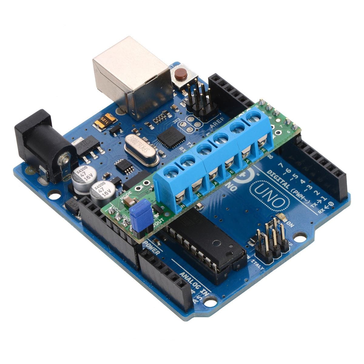
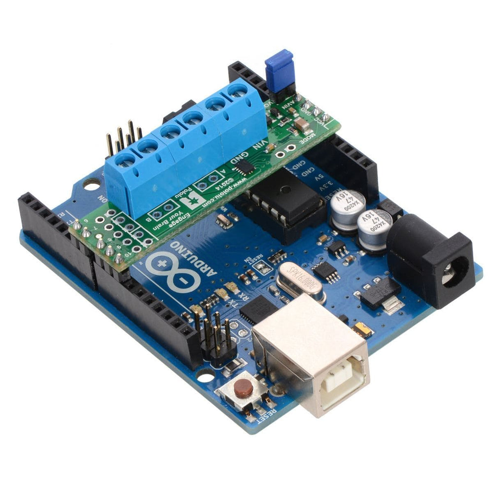
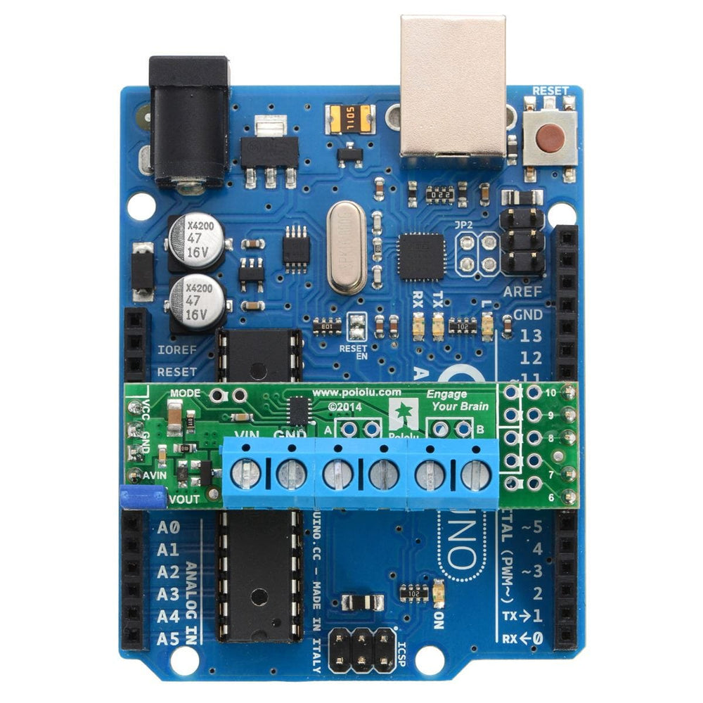
The shield plugs into Arduino digital pins 6, 7, 8, 9, and 10 on one side and Arduino VIN, GND, GND, and 5V/VCC on the other. The upper-left corner of the shield partially blocks the Arduino’s 3.3V pin, but this region of the board (marked with a white silkscreen box) can be removed if necessary to allow access. The shield also blocks Arduino digital pin 6, but it provides alternate access points to this pin via the neighbouring through-holes. The board does not use pin 6 for anything.
In the shield’s default state, the motor driver shield and Arduino are powered separately, though they share a common ground and the Arduino’s 5V rail serves as the shield’s logic supply. When used this way, the Arduino must be powered via USB, its power jack, or its VIN pin, and the shield must be supplied with 1.5 V to 11 V through its large VIN and GND pads.
Attempting to power the shield from the Arduino is not recommended as this could result in large currents flowing through small traces. However, if the motor power supply is suitable, it is possible to power the Arduino from the shield. This can be accomplished by placing a jumper between the shield pins in the lower-left corner labelled VOUT and AVIN, which connects the reverse-protected motor supply voltage to the Arduino’s VIN pin to power the Arduino. The Arduino’s power jack must remain disconnected at all times in this configuration.
Warning: When powering the Arduino from the motor shield, you must never connect a different power supply to the Arduino’s VIN pin or plug a power supply into the Arduino’s power jack, as doing so will create a short between the shield’s power supply and the Arduino’s power supply that could permanently damage both the Arduino and the motor shield. In this case, it is also important that your shield power supply is an acceptable voltage for your Arduino, so the full shield operating voltage range of 1.5 V to 11 V probably will not be available. For example, the recommended operating voltage of the Arduino Uno is 7 – 12 V.
By default, the board operates in PHASE/ENABLE mode, in which a PWM signal applied to the ENABLE pin determines motor speed and the digital state of the PHASE pin determines the direction of motor rotation. Arduino pins 9 and 7 are used to control the speed and direction, respectively, of motor 1, and pins 10 and 8 control the speed and direction of motor 2. The table below shows how the inputs affect the outputs in this mode:

PHASE/ENABLE mode should be suitable for most applications.
The operating mode of the driver is controlled by the MODE pin, which the shield connects to VCC by default to select PHASE/ENABLE mode.
To change the mode, locate the pair of 0.1″ through-holes in the upper-left part of the board labelled “MODE” and use a knife to cut the trace that connects the two on the bottom side of the PCB. Since the MODE pin has an internal pull-down resistor, severing its connection to VCC is all it takes to switch the control interface to IN/IN, which allows for slightly more advanced control options as described in the table below:

Once the trace between the two pins has been cut, you can use a pair of header pins and a shorting block to control the mode: with the shorting block on, the mode is PHASE/ENABLE; with it off, the mode is IN/IN.
IN/IN mode is generally only useful if you only care about on/off control of the motors or if you can supply PWM signals to all four inputs, which is not possible when using the default pins on an Arduino Uno. If you want to be able to control the speed of the motors when using this mode, you should either remap the control pins or select an Arduino that can generate PWM signals with digital pins 7, 8, 9, and 10 (like the Arduino Mega 2560).
In order to use the two motor channels in parallel to control a single motor, it is important to ensure that both channels will always receive the same control signals, so the reconfiguration process begins with a modification to the control inputs.
First, locate the 2×5 grouping of 0.1″ through-holes along the right side of the board. These holes run parallel to pins 6-10 and the traces between them on the underside of the PCB effectively link the Arduino pins to the DRV8835 control pins. If you want to remap one of these control pins, you can cut the desired trace with a knife and then run a wire from the inner hole to a new Arduino pin. The remapping for single-channel mode requires you cut one PWM (9 or 10) and one DIR (7 or 8) trace; cut 10 and 8 to control both outputs from the motor 1 input pins, or cut 9 and 7 to control both from the motor 2 input pins. If you then solder a row of header pins along the interior row of holes, you can safely connect both PWM lines together and both DIR lines together using shorting blocks. In this configuration, the two uncut Arduino control lines determine the behavior of both motor channels.
The last step is to connect the output channels together. An easy way to do this is to solder header pins to the two pairs of holes labeled “A” and “B” near the motor outputs. Placing shorting blocks across these pairs of pins connects M1A to M2A and M1B to M2B, which in turn means you can get up to 3 A from the connection points for either channel (e.g. you can have your motor connected just to the M1A and M1B terminal blocks rather than trying to find a way to connect it to all four motor outputs).
The DRV8835 datasheet recommends a maximum continuous current of 1.5 A per motor channel. However, the chip by itself will overheat at lower currents.
For example, in our tests at room temperature with no forced airflow, the chip was able to deliver 1.5 A per channel for approximately 15 seconds before the chip’s thermal protection kicked in and disabled the motor outputs, while a continuous current of 1.2 A per channel was sustainable for many minutes without triggering a thermal shutdown.
The actual current you can deliver will depend on how well you can keep the motor driver cool. The carrier’s printed circuit board is designed to draw heat out of the motor driver chip, but performance can be improved by adding a heat sink. Our tests were conducted at 100% duty cycle; PWMing the motor will introduce additional heating proportional to the frequency.
This product can get hot enough to burn you long before the chip overheats. Take care when handling this product and other components connected to it.
Your payment information is processed securely. We do not store credit card details nor have access to your credit card information.