Pololu Breakout Board for MicroSD Cards
Price:
Sale price
£4.80
Stock:
Quantity:
Login / Signup
Cart
Your cart is empty


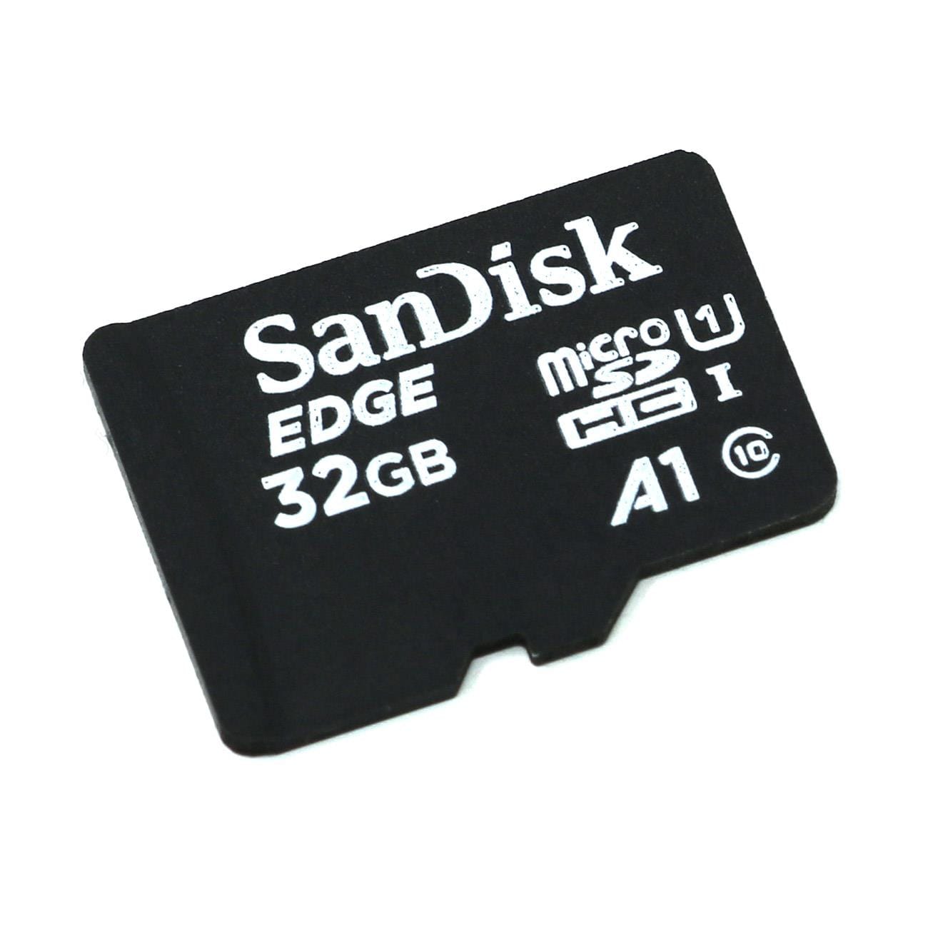
MicroSD memory cards (originally known as TransFlash) provide a compact and inexpensive way to add gigabytes of non-volatile storage to a project. All SD cards support communication over the SPI (Serial Peripheral Interface) bus, making it straightforward to interface one of these cards with an SPI-capable microcontroller.
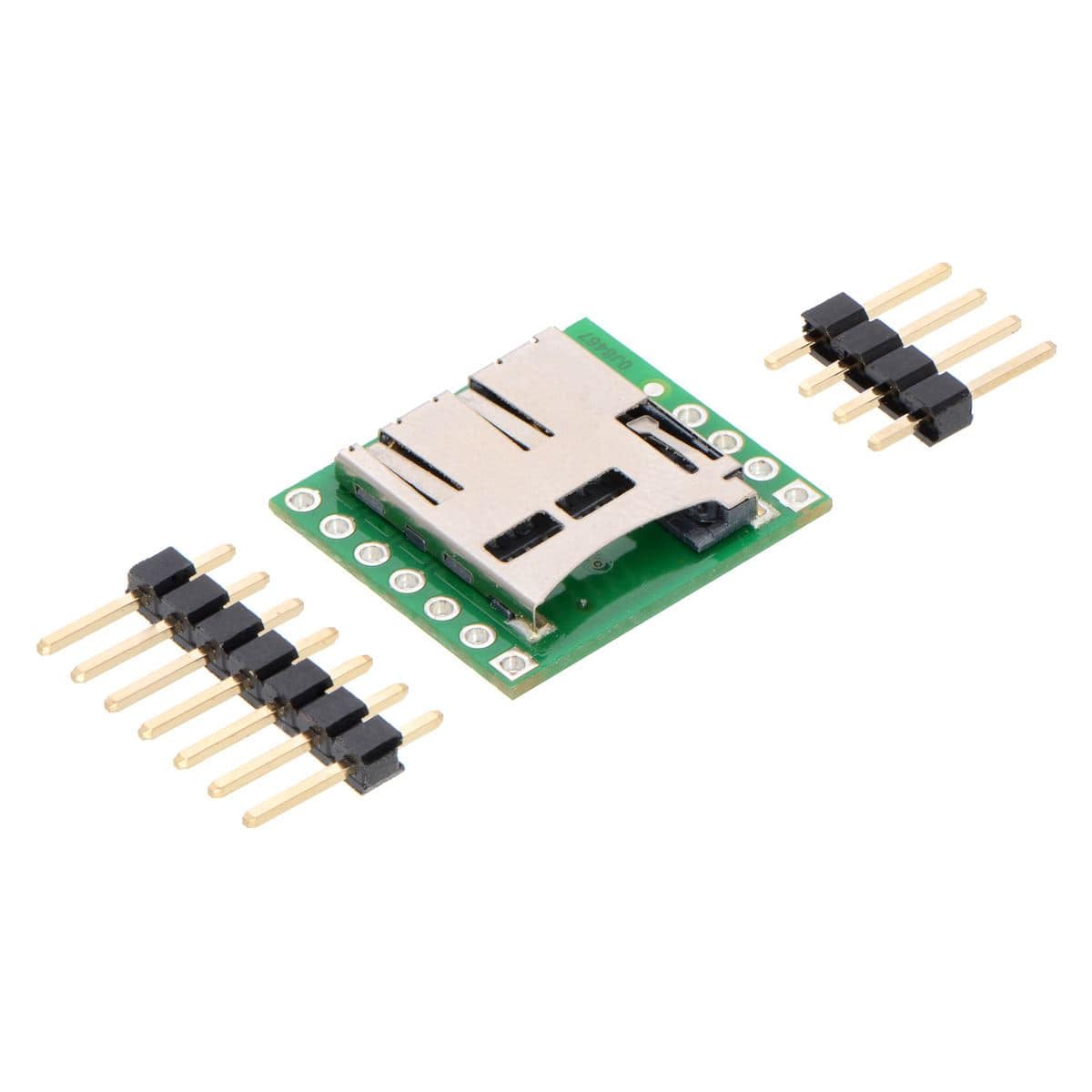
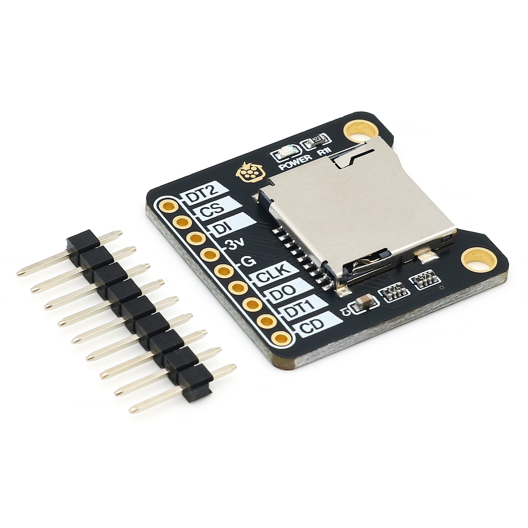
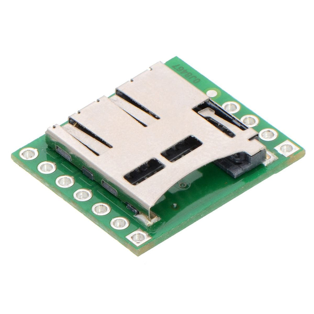
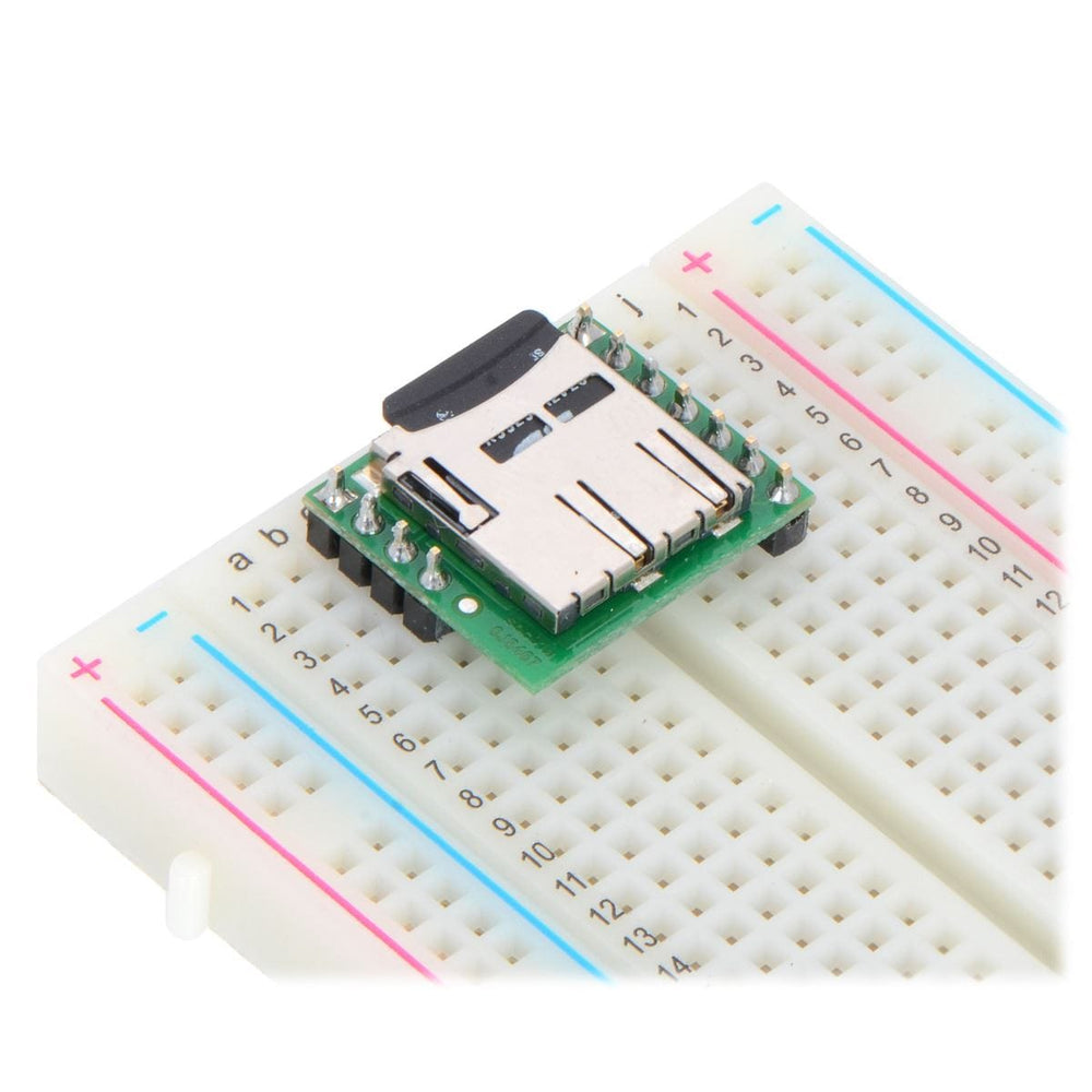
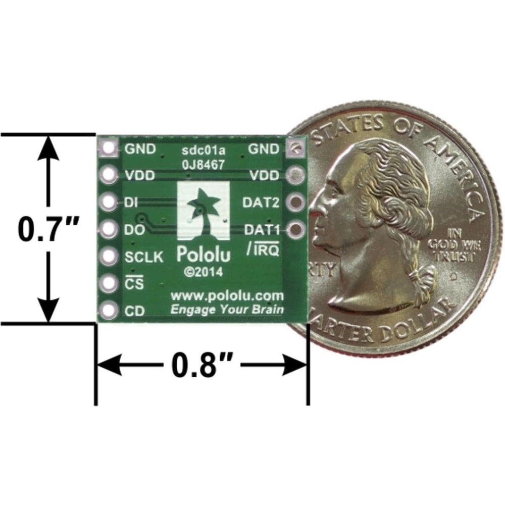
This carrier board makes it easy to connect to a MicroSD card by breaking out all of the contacts from a MicroSD card socket into two rows of 0.1″-spaced pins. The board measures only 0.8″ × 0.7″, and a set of breakaway 0.1″ male header strips (one 1×7 and one 1×4) is included, which can be soldered in to use the board with breadboards, perfboards, or 0.1″ female connectors. (The headers might ship as a single 1×11 piece that can be broken in two).
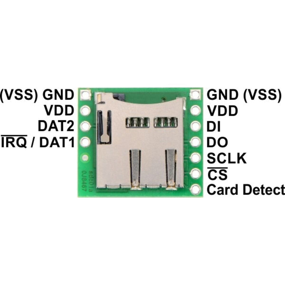
Since many microcontrollers have built-in SPI interfaces, most hobbyist projects communicate with Secure Digital cards in SPI bus mode. (The alternative SD bus mode is proprietary, and a license from the SD Association is required for access to the full specifications.) Where applicable, the pins on this board are labelled according to their functions in SPI mode.
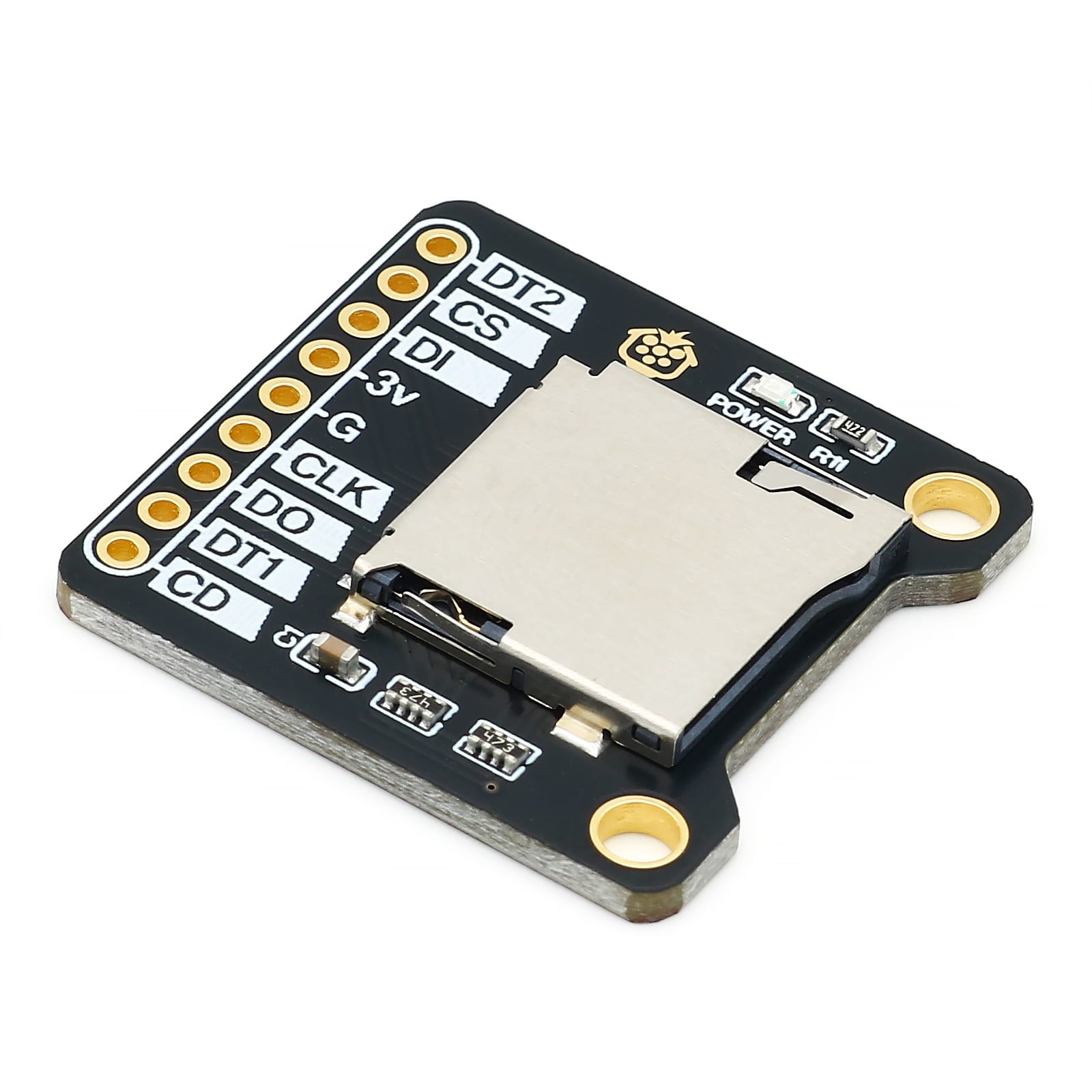
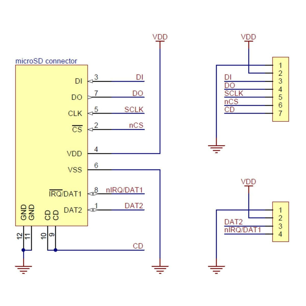
All of the microSD card’s power pins and all of the signal pins necessary to interface with the card through SPI are available along the right side of the board. The left side of the board exposes duplicate power pins, along with two additional signal lines (DAT1 and DAT2) that are not needed for SPI communication but are used in 4-bit SD bus mode. The DAT1 pin also serves as an interrupt pin (IRQ) in SDIO devices. (Note that if you are using this module in a breadboard, you might want to solder header pins into both sides of the board for added stability even if you only plan to use the SPI pins.)

The following tables describe the function of each pin on the breakout board in SPI and SD mode:

Warning: Standard microSD cards use 3.3V logic level signals, so level shifters or voltage dividers are required when connecting one to a 5V system.
The SD Association publishes a set of simplified specifications for SD cards containing information on interfacing with them. However, there are a number of ways to get started without understanding the specifications or writing your own code from scratch, since many microcontroller development platforms provide libraries for communicating with SD cards. For example:
Your payment information is processed securely. We do not store credit card details nor have access to your credit card information.